
myAIRVO™2
myAIRVO™ 2
User Manual
........................................................................... SECTION
English ..........................................................................A
Español .........................................................................B
Français ........................................................................C
繁体中文 (Chinese Traditional) .............................D
• This User Manual is intended for patients.
• Read this User Manual including all warnings and watch the myAIRVO 2 Video Guide. Keep them both in
a safe place for future reference.
• Before the myAIRVO 2 is used for the first time, it must be set up according to the instructions in the
myAIRVO 2 Technical Manual. This should be carried out by a healthcare professional or medical technician.
• If the unit is ever used by multiple patients, the unit must be cleaned and disinfected between patients
according to instructions in the Disinfection Kit Manual.
• For further assistance, please contact your Fisher & Paykel Healthcare representative.
TABLE OF CONTENTS
1.Overview .......................................................................................................................................................A - 2
Intended Use .................................................................................................................................................................................A - 2
Warnings .........................................................................................................................................................................................A - 2
myAIRVO 2 and Accessories ..................................................................................................................................................A - 3
2. Setting up myAIRVO 2 ............................................................................................................................A - 4
3. Using myAIRVO 2 ......................................................................................................................................A - 7
Advanced settings ......................................................................................................................................................................A - 8
Oxygen ............................................................................................................................................................................................A - 10
Alarms ..............................................................................................................................................................................................A - 11
4. Cleaning and maintenance ....................................................................................................................A - 12
Daily cleaning instructions .......................................................................................................................................................A - 12
Weekly cleaning instructions ..................................................................................................................................................A - 12
Schedule for changing accessories ......................................................................................................................................A - 13
Filter replacement .......................................................................................................................................................................A - 13
Servicing .........................................................................................................................................................................................A - 13
5. Technical Information ..............................................................................................................................A - 14
A–1
English
BEFORE YOU START
1. OVERVIEW
The myAIRVO 2 is a humidifier with integrated flow generator that delivers warmed and humidified respiratory
gases to spontaneously breathing patients through a variety of patient interfaces.
INTENDED USE
The myAIRVO 2 is for the treatment of spontaneously breathing patients (adult and pediatric > 3 kg) who
would benefit from receiving warmed and humidified respiratory gases. This includes patients who have had
upper airways bypassed. The myAIRVO 2 is for patients in homes and long-term care facilities.
USA Federal Law restricts this unit for sale by or on the order of a physician.
!
WARNINGS
• Nasal delivery of respiratory gases generates flow-dependent positive airway pressure (PAP). This must
be taken into account where PAP could have adverse effects on a patient.
• The myAIRVO 2 humidifier (hereafter referred to as “the unit”) should only be used with
interfaces, water chambers and breathing tubes recommended by Fisher & Paykel Healthcare.
• The unit is not intended for life support.
• Using the breathing tube or interface for longer than the specified time can result in serious injury
including infection.
• Do not store or use the unit where it can fall or be pulled into water. If water has entered the unit enclosure,
disconnect the power cord and discontinue use.
• Never operate the unit if:
• it has a damaged power cord or plug,
• the heated breathing tube has been damaged with holes, tears or kinks,
• it has been dropped or damaged,
• it has been dropped into water,
• it is not working properly,
• the case screws have ever been loosened.
• Do not use the unit when the room temperature exceeds 30°C (86°F) or is below 10°C (50°F) as the unit
may switch off. Humidity output will be compromised below 18°C (64°F) and above 28°C (82°F).
• Avoid unnecessary removal of the power cord from the rear of the device. If removal is necessary, hold the
connector during removal. Avoid pulling on the power cord.
• Ensure an air filter is fitted when operating your unit.
• Never block the air openings of the unit or place it on a soft surface such as a bed or couch/sofa, where
the filter area may be blocked. Keep the air openings free of lint, hair etc.
• The unit should be located in a position where ventilation around the unit is not restricted.
• Do not block the flow of the air through the unit and breathing tube.
• Never drop or insert any object into any opening or tube.
• Return the unit to an authorized service center for examination and repair, except as outlined in this
manual.
• The unit is not suitable for use in the presence of a flammable, anesthetic mixture with air or oxygen or
nitrous oxide.
A–2
myAIRVO 2 AND ACCESSORIES
MUTE
English
ON/OFF (STANDBY)
Patient
interface
UP
DISPLAY
DOWN
Heated
breathing
tube
MODE
WATER BAG
OXYGEN
INLET PORT
HEATED BREATHING TUBE
CONNECTION PORT
CHAMBER PORTS
COMPACT STAND
SERIAL PORT
POWER CORD
and
CONNECTOR
FILTER COVER
myAIRVO 2
(PT100AZ/
PT100UK/
PT100US)
REUSABLE WATER
CHAMBER (HC360)
HEATER
PLATE
FINGER
GUARD
Water chamber
AUTO-FILL WATER
CHAMBER (MR290)
(with adapter fitted)
AIR FILTER
Tube & chamber kits and patient interfaces
Tube & chamber kit
900PT531
Interfaces
Heated breathing tube,
MR290 auto-fill chamber and
adapter (10-Pack)
à
900PT500
Heated breathing tube
à
900PT501
Heated breathing tube,
MR290 auto-fill chamber and
adapter (10-Pack)
à
OPT316
OPT318
Nasal Cannula - Infant (20-Pack)
Nasal Cannula - Pediatric (20-Pack)
OPT842
OPT844
OPT846
OPT870
RT013
Nasal Cannula - Small (20-Pack)
Nasal Cannula - Medium (20-Pack)
Nasal Cannula - Large (20-Pack)
Tracheostomy Direct Connection (20-Pack)
Mask Interface Adapter - 22mm (20-Pack)
Miscellaneous
900PT400
900PT401
900PT403
900PT422
900PT911
900PT912
900PT913
HC360
Compact stand (for myAIRVO 2 and water bag)
Water bag (2-pack)
Heated breathing tube cover
Oxygen inlet extension kit
Non-return valve
Filter holder
Air filter (2-Pack)
Reusable water chamber
A–3
2. SETTING UP myAIRVO 2
1. BEFORE YOU BEGIN
Place the unit on a low shelf or near the floor beside your bed. It must be
placed below head height and flat.
2. INSTALL WATER CHAMBER
IF USING A HC360 REUSABLE WATER CHAMBER:
With the aid of the supplied funnel, fill the chamber with enough distilled
water for the period of use, but never above the 560 mL fill line.
HC360: Flow setting vs usage time
L/min
5
10
15
20
25
30
35
40
45
50
hrs
47
23
16
12
9
8
7
6
5
5
WARNINGS
• Do not fill the water chamber with water above 55°C (131°F).
• Always remove the water chamber to fill it and always fill with enough distilled
water to prevent it running out.
Fit the water chamber to the unit by pressing down the finger guard and
sliding the chamber on, carefully aligning with the blue chamber port ends.
Push the chamber on firmly. When the chamber is fitted correctly the
finger guard will click into place and there should be a gap of about 2 mm
(1/16”) between the finger guard and the rim on the base of the chamber.
Go to Step 3, “Install Heated Breathing Tube”, below.
IF USING THE MR290 AUTO-FILL WATER CHAMBER:
Remove the blue port caps from the chamber by pulling the tear tab
upwards then remove the bracket holding the water supply tube. Fit the
supplied adapter over the two vertical ports on the chamber and push on
fully then clip the water supply tube into position.
Fit the MR290 chamber as described above for the HC360 chamber.
H2O
Attach the water bag to the hanging bracket at least 20cm (8”) above
the unit, and push the bag spike into the fitting at the bottom of the bag.
Open the vent cap on the side of the bag spike. The chamber will now
automatically fill to the required level and maintain that level until the
water bag is empty.
A–4
MR290: Flow setting vs usage time
(Water bag 900PT403, 1 L)
L/min
5
10
15
20
25
30
35
40
45
50
hrs
47
23
16
12
9
8
7
6
5
5
WARNINGS
• Do not start the unit without the water chamber in place.
• Do not touch the heater plate, water chamber or chamber base, as they become
hot in normal use.
• When handling the unit with the water chamber in place, avoid tilting the
machine to prevent any chance of water entering the unit enclosure.
• Empty all the water from the water chamber before transporting the unit.
• The water in the chamber becomes hot during use. Exercise caution when
removing and emptying the chamber.
HC360 only:
• The HC360 chamber is not intended for use with Optiflow Junior nasal cannulas.
MR290 only:
• Use only distilled water and always ensure sufficient water is in the water bag to
prevent it from running out.
• Do not use the auto-fill MR290 chamber if it has been dropped, or been run dry
and the “water out” alarm has been activated.
3. INSTALL HEATED BREATHING TUBE
One end of the heated breathing tube has a blue plastic sleeve. Lift the
sleeve and slide the connector onto the unit. Push the sleeve down to
lock.
WARNINGS
• Do not modify the breathing tube or interface in any way.
• Do not allow the breathing tube to remain in direct contact with skin for
prolonged periods of time.
• Adding heat, above ambient levels, to any part of the breathing tube or interface
e.g. covering with a blanket, or heating it in an incubator or overhead heater for a
neonate, could result in serious injury.
• Do not use an insulating sleeve or any similar accessories which are not
recommended by Fisher & Paykel Healthcare.
• Position the heated breathing tube away from any electrical monitoring leads
(EEG, ECG/EKG, EMG, etc), to minimize any possible interference with the
monitored signal.
A–5
English
Check that water flows into the chamber and is maintained below the
fill line. If the water level rises above the fill line, replace the chamber
immediately.
4. SELECT PATIENT INTERFACE
The myAIRVO 2 can be used with a variety of patient interfaces. Read the separate user instructions for
the patient interface that will be used, including all warnings.
WARNINGS
• Do not modify the breathing tube or interface in any way.
• Do not use any patient interfaces not listed here.
Nasal Cannula
(OPT842/OPT844/OPT846)
If using the nasal interface, place the lanyard around the neck.
Hold the nasal interface in the nose and then place the elastic
loop behind the head, above the ears.
The elastic loop can be adjusted by pulling it at the sides.
Adjust the larger loop around the neck if necessary, so that the
head can be moved without the loop pulling.
Nasal Cannula
(OPT316/OPT318)
Refer to separate user instructions.
2
VO
R
I
A
TM
Tracheostomy Interface
(OPT870)
If using the tracheostomy interface, place the lanyard around
the neck, attach the tracheostomy tube connector as shown,
and adjust the length of the strap for maximum comfort.
Mask Interface Adapter
(RT013)
If using a standard vented tracheostomy or face mask, connect
the mask’s 22 mm connector to the RT013 Mask Interface
Adapter. Place the lanyard around the neck and fit the mask in
the usual manner.
WARNINGS
• Note that the RT013 Mask Interface Adapter is designed to be used
with vented masks only. Do not use sealed masks.
A–6
3. USING myAIRVO 2
Plug the unit’s power cord into the mains power supply. The connector
at the other end of the power cord should be well secured to the rear of
the unit.
WARNINGS
• Ensure that the unit is dry before plugging into the power socket.
Switch on the unit by pressing the On/Off button.
2. WARM-UP
The unit will begin to warm up. You will see a warm-up symbol on the
screen.
“Warm-up” symbol
3. CONNECT THE PATIENT INTERFACE
When the “Ready for Use” symbol appears on the display, connect the
patient interface to the heated breathing tube.
“Ready for use” symbol
When you first use the unit, the air will feel warm. Continue to breathe
normally.
4. AFTER USE
When you have finished using the unit, remove your interface and drain
any excess condensate in the breathing tube by lifting the patient end
of the tube, and allowing the condensate to run into the water chamber.
5. DRYING MODE
Then press and hold the On/Off button for 3 seconds until a melody
sounds. The unit will automatically enter Drying Mode and dry the tube
so it is ready for you to use next time. Drying Mode runs for 99 minutes.
The unit will automatically turn off when it is finished.
WARNINGS
• Do not wear the interface during Drying Mode. The air is hot and dry and may
cause injury.
• Do not remove the water chamber until drying mode has been completed.
To switch the unit off without completing Drying Mode (this is not
recommended), hold down the On/Off button for 5 seconds.
If you unplug the unit’s power cord from the mains power supply while
the unit is still running, the “Power Out” alarm will sound. Press the Mute
button to silence this alarm.
A–7
English
1. SWITCH ON UNIT
ADVANCED SETTINGS
When you see the “Warm-up” or “Ready for use” symbols, you can
press the Mode button to view and change advanced settings.
TARGET DEW-POINT TEMPERATURE
You can set the myAIRVO 2 to three target dew-point temperature
settings:
• 37°C (98.6°F) [recommended]
• 34°C (93°F) [if compliance at 37°C is a problem]
• 31°C (88°F) [for face masks only].
You may not have access to all settings, if:
• the unit is in Junior Mode (limited to 34 °C),
• the unit was initially set up with tighter limits.
The myAIRVO 2 will remember its target dew-point temperature setting
when you switch it off.
To change the target dew-point temperature
setting:
Press the Up and Down buttons to choose the new
setting.
The large number in the center of the screen shows
your chosen setting.
The small numbers near the arrow show the minimum
and maximum accessible settings.
Press the Mode button to move on to the next screen.
TARGET FLOW
You can set the myAIRVO 2 to flows between 15 L/min and 50 L/min, in
increments of 5 L/min.
You may not have access to all settings, if:
• the unit is in Junior Mode (limited to 5 - 20 L/min),
• the unit was initially set up with tighter limits.
The myAIRVO 2 will remember its target flow setting when you switch
it off.
To change the target flow setting:
Press the Up and Down buttons to choose the new
setting.
The large number in the center of the screen shows
your chosen setting.
The small numbers near the arrow show the minimum
and maximum accessible settings.
Press the Mode button to move on to the next screen.
A–8
DAY/NIGHT MODES
In “Night” mode, some of the myAIRVO 2 sounds will be made quieter.
The display will become dimmed. Alarms will be unaffected.
The myAIRVO 2 will remember its Day/Night setting when you switch it
off.
To change the Day/Night setting:
Press the Up and Down buttons to choose the new
setting.
à “Day”
à “Night”
Press the Mode button to move on to the next screen.
COMPLIANCE
This screen displays three pieces of compliance data:
Total hours used
83
Total hours used
Displays the total number of hours that the unit has
been switched on.
Hours per day
Displays the average number of hours that the unit has
been used per day.
Checksum
Displays usage information for the medical practitioner.
Press the Mode button to return to the “Warm-up”/”Ready for use”
screen.
JUNIOR MODE
If the patient will be using an Optiflow Junior nasal cannula (OPT316/OPT318), you must activate Junior
Mode.
Junior Mode limits the target settings to: 34 °C and 5 - 20 L/min.
To activate Junior Mode:
You must be able to see the “Warm-up” symbol or the “Ready for use” symbol to activate
Junior Mode.
Hold the Mode button for 5 seconds.
New target
settings
New target settings
The target settings for dew-point temperature and flow will be changed automatically. The
butterfly and bird in the corners of the screen indicate that this unit is in Junior Mode.
No “Check water” alarm in Junior Mode
The "Check water" alarm will not operate in Junior Mode due to the lower flows used. To
ensure continual humidification, always ensure that the water chamber and/or water bag
are not allowed to run out of water.
To deactivate Junior Mode, follow the same procedure: hold the Mode button for 5 seconds.
A–9
English
You can set the myAIRVO 2 to “Day” mode or “Night” mode.
OXYGEN
You can connect supplementary oxygen to the myAIRVO 2. Connect the
output from the oxygen source to the oxygen inlet port on the back of the
unit. Make sure you push the oxygen tube firmly onto this connection port.
The fraction of oxygen you breathe with this air/oxygen mixture is
determined by the airflow setting on the unit and the oxygen flow
connected to the unit’s oxygen inlet port.
The following table gives the approximate oxygen fraction delivered for
the range of unit and oxygen airflows. The oxygen fractions given assume
that the oxygen source is a home oxygen concentrator. These values will
be higher if the oxygen source is bottled oxygen.
Oxygen Flow
(L/min)
myAIRVO 2 Target Flow Setting (L/min)
15
20
25
30
35
40
45
50
25
24
23
23
23
22
22
22
2
31
28
27
26
25
25
24
24
3
35
32
29
28
27
26
26
25
1
4
41
36
33
31
29
28
28
27
5
47
40
36
34
32
31
30
29
It is important that the physician prescribing your oxygen therapy
approves both the flow and oxygen settings and that you do not adjust
these prescribed settings without consulting them.
Continual pulse oximetry is recommended for patients who would
desaturate significantly in the event of disruption to their oxygen supply.
WARNINGS
Before using oxygen with the unit, read all of the following warnings:
• The use of oxygen requires that special care be taken to reduce the risk of fire.
Accordingly, for safety it is necessary that all sources of ignition be kept away from
the unit and preferably out of the room in which it is being used. Oxygen should
not be used while smoking or in the presence of an open flame. The unit should be
located in a position where ventilation around the unit is not restricted.
• A spontaneous and violent ignition may occur if oil, grease or greasy substances
come in contact with oxygen under pressure. These substances must be kept away
from all oxygen equipment.
• Ensure that the myAIRVO 2 is switched on before connecting oxygen.
• Oxygen must only be added through the special oxygen inlet port on the back of
the unit. To ensure that oxygen enters the unit correctly, the oxygen inlet port must
be fitted properly to the filter holder and the filter holder must be fitted properly to
the unit. The power cord connector should also be well secured.
• The oxygen concentration delivered to the patient can be affected by changes to
the flow setting, oxygen setting, patient interface or if the airpath is obstructed.
When finished, turn off the oxygen source. Remove the output of the
oxygen source from the oxygen inlet port on the back of the unit. The
oxygen flow must be turned off when the unit is not operating, so that
oxygen does not build up inside the device.
A – 10
The myAIRVO 2 has visual and auditory alarms to warn you about interruptions to your patient’s
treatment.
All of the alarms listed below have been assessed as “Medium Priority”. These priorities have been
allocated for an operator’s position within 1 meter of the device.
Symbols
Meaning
Alarm condition.
(message)
Auditory alarm is muted
Press this button to mute the auditory alarm for 115 seconds.
The auditory alarm can be reactivated by pressing this button
again.
Message
Fault
(E###)
Meaning
A fault has occurred and the unit has been shut down.
Switch the unit off and then restart. If the problem persists, note the fault code and contact your
Fisher & Paykel Healthcare representative.
Check for leaks The most likely cause is that the water chamber has been removed or has not been pushed into
place correctly.
Check that the filter is fitted.
Junior Mode: Check that the nasal interface is fitted.
Check for
blockages
Check the heated breathing tube or patient interface for blockage.
Check the air filter and filter holder for blockage.
Check whether the unit should be in Junior Mode. If the patient will be using an Optiflow Junior
nasal cannula (OPT316/OPT318), you must activate Junior Mode.
Check tube
The unit cannot detect the heated breathing tube.
Check that the heated breathing tube is not damaged and that it is plugged in correctly. If the
problem persists, then change the heated breathing tube.
Check water
Note that this alarm is not activated until the chamber has been dry for approximately 30 minutes.
The chamber has run out of water.
If using the HC360 reusable chamber: Remove the chamber and refill.
If using the MR290 auto-fill chamber: When a chamber runs dry, the chamber float may be
damaged. Replace the chamber and water bag.
Twenty seconds after the chamber is removed, the “Check for leaks” alarm is activated (see above).
When the chamber is replaced, the unit enters Warm-up Mode and resumes normal operation.
The “Check water” alarm will not operate in Junior Mode. To ensure continual humidification, always
ensure that the water chamber and/or water bag are not allowed to run out of water.
Cannot
reach target
temperature
The most likely cause for this is that the unit is operating at a high flow rate in low ambient conditions.
You will be prompted for acknowledgement.
Cannot reach
target flow
Check whether the target flow setting is too high for the patient interface being used (refer to
“Setting up myAIRVO 2” - ”Select Patient Interface”).
The unit will choose appropriate new target settings. You will be prompted for acknowledgement.
Note: The oxygen concentration delivered to the patient can be affected by changes to the flow
setting.
Check
operating
conditions
[Power out]
Do not use the device when the ambient temperature is less than 10°C.
Do not use the device when the ambient temperature is greater than 30°C.
No visual alarm. The auditory alarm will sound for at least 120 seconds.
TESTING ALARM FUNCTIONALITY
The visual and auditory alarm signals can be checked by removing the heated breathing tube from the
unit while it is running. An alarm should sound and the “Check tube” warning described above should be
displayed.
A – 11
English
ALARMS
4. CLEANING AND MAINTENANCE
The following instructions are for single-patient home use.
If the unit is ever used by multiple patients, the unit must be cleaned and disinfected between patients
according to instructions in the Disinfection Kit Manual (900PT600). In addition, the patient interface,
heated breathing tube and water chamber must be changed between patients.
Standard aseptic techniques to minimize contamination should be followed when handling the unit
and accessories. This includes proper hand-washing, avoiding hand contact with connection ports, safe
disposal of the used consumables and suitable storage of the unit after cleaning and disinfection.
DAILY CLEANING INSTRUCTIONS
Run Drying Mode / Rinse the patient interface and water chamber
1. Allow Drying Mode to run after use (refer “Using myAIRVO 2” - “Drying Mode”).
2. Remove the interface, clean and rinse in drinking-quality water then reconnect to the heated breathing
tube whilst still in Drying Mode to dry the interface.
3. After Drying Mode is complete, remove the water chamber by pushing down the finger guard and
pulling out the chamber. Wash and rinse the chamber then refill it with sufficient distilled water for the
next use.
WEEKLY CLEANING INSTRUCTIONS
Clean the patient interface, water chamber and myAIRVO 2
1. Switch off the unit and unplug from the power socket.
2. Remove the heated breathing tube and drain any excess condensate.
3. Remove the interface from the heated breathing tube, wash it in warm water with mild dishwashing
detergent added, rinse it in drinking-quality water, then reconnect it to the heated breathing tube.
4. Remove the water chamber.
If using the HC360 reusable chamber:
Pour out and discard the remaining water. Remove the chamber base.
Wash the chamber top and base in mild dishwashing detergent then
rinse. Soak the chamber in a solution of vinegar (1 part) and water (2
parts) for 10 minutes. Rinse and dry.
If using the MR290 chamber:
Do not wash this chamber. Carefully put the MR290 chamber aside.
5. Thoroughly wipe the inside of the heated breathing tube connection port with a clean, low-lint cloth
dipped in warm water with mild dishwashing detergent added.
6. Wipe the exterior of the unit with a clean, damp (not wet) cloth dipped in warm water with mild
dishwashing detergent added. Do not use harsh abrasives or solvents, as these may damage the unit.
7. Refit the heated breathing tube.
8. If using the HC360 chamber: Refit the chamber.
9. If using the MR290 chamber: Refit the MR290 chamber and reconnect to the water bag. Check that
water flows into the chamber and is maintained below the fill line. If the water level rises above the fill
line, replace the chamber immediately
10. Reconnect the unit to the power supply.
11. The unit is now ready for another week of use.
A – 12
The accessories for the unit must be changed frequently to avoid the risk of infection. Parts should be
replaced immediately if they are damaged or discolored; otherwise they must be replaced within the
periods shown in the following table. These periods assume that the correct daily and weekly cleaning
procedures and maintenance schedule described above are adhered to. These accessories are for singlepatient use only.
Maximum
period of use
Part number and description
Optiflow Junior interfaces
1 week
OPT316
OPT318
Nasal Cannula - Infant
Nasal Cannula - Pediatric
All other patient interfaces
1 month
OPT842 / OPT842E
OPT844 / OPT844E
OPT846 / OPT846E
OPT870 / OPT870E
RT013 / RT013E
Nasal Cannula - Small
Nasal Cannula - Medium
Nasal Cannula - Large
Tracheostomy Interface
Mask Interface Adapter - 22mm
All tube & chamber kits
2 months
3 months
or
1000 hours
Reusable
900PT500 / 900PT500E
900PT290E
900PT501
900PT531
Heated breathing tube
MR290 auto-fill chamber and adapter
Heated breathing tube, MR290 auto-fill chamber and adapter
Heated breathing tube, MR290 auto-fill chamber and adapter
(for use with OPT316/OPT318 only)
900PT424 Air filter
(or more often if significantly discolored)
HC360
Reusable water chamber
FILTER REPLACEMENT
If the unit tells you that a filter change is due:
Air filter change
due
1.
2.
Take the filter holder from the back of the unit and remove the filter.
Replace the old filter with a new one.
3.
Reattach the filter holder to the unit (clip the bottom of the filter
holder in first, then rotate it upwards until the top clips into place).
Press the Mode button to move on to the next screen.
4.
SERVICING
This device contains no serviceable parts.
A – 13
English
SCHEDULE FOR CHANGING ACCESSORIES
5. TECHNICAL INFORMATION
SYMBOL DEFINITIONS
Caution
Hot Surfaces
Type BF
Applied Part
ATTENTION
Consult
accompanying
documents
Do not
throw away
Drip Proof
Alternating
Current
Class ll
Double
Insulated
Power
On/Off
(Standby)
93/42/EEC
Class IIb
PRODUCT SPECIFICATIONS
Dimensions
295 mm x 170 mm x 175 mm
(11.6” x 6.7” x 6.9”)
Weight
2.2 kg (4.8 lb) unit only,
3.4 kg (7.5 lb) packaged in bag
incl. accessories
Supply frequency
50-60 Hz
Supply voltage/current 100-115 V 2.1 A (2.2 A max)
220-240 V 1.5 A (3.2 A max)
Sound pressure level
Alarms exceed 45 dbA @ 1 m
Auditory alarm pause
115 seconds
Serial port
The serial port is used for
downloading product data,
using F&P Infosmart™ software.
Humidity
>33 mg/L at 37 °C target
>10 mg/L at 34 °C target
>10 mg/L at 31 °C target
Maximum temperature
43 °C (109 °F)
of delivered gas
Maximum flow range
(default)
15-50 L/min
Maximum flow range
(Junior Mode)
5-20 L/min
Warm-up time
10 minutes to 31 °C (88 °F),
30 minutes to 37 °C (98.6
°F) using a MR290 chamber
with flow rate of 35 L/min and
starting temperature 23 ± 2 °C
(73 ± 3 °F)
Designed to conform to the requirements of:
IEC 60601-1
UL 60601-1
CSA C22.2/No. 601.1
AS 3200.1.0
EN 60601-1
The unit complies with the electromagnetic compatibility requirements of IEC 60601-1-2. In
certain circumstances, the unit may affect or be affected by nearby equipment due to the
effects of electromagnetic interference. If this should happen, try moving the unit or the
location of the unit causing interference, or alternatively consult your healthcare provider.
Accessory equipment connected to the serial port of the device must be certified to either IEC 60601-1 or IEC
60950-1. Furthermore all configurations shall comply with the system standard IEC 60601-1-1. Anyone who connects
additional equipment to the signal input part or signal output part configures a medical system and is therefore
responsible for ensuring that the system complies with the requirements of the system standard IEC 60601-1-1. If in
doubt, consult the technical services department or your local representative.
OPERATING CONDITIONS
Recommended ambient temperature
18 to 28 °C (64 to 82 °F)
Minimum/maximum ambient temperature
10 to 30 °C (50 to 86 °F)
Humidity
10 to 95% RH
Altitude
0 to 2000 m (6000 ft)
Mode of operation
Continuous operation
STORAGE AND TRANSPORT CONDITIONS
The unit should be stored and transported in environmental conditions of -10 °C to 60 °C (14 °F to 140 °F),
10 to 95% RH, non-condensing.
DISPOSAL INSTRUCTIONS
Unit Disposal Instructions
This unit contains electronics. Please do not discard with regular waste. Return to Fisher & Paykel
Healthcare or dispose according to local guidelines for disposing of electronics. Dispose according to Waste
Electrical and Electronic Equipment (WEEE) directive in European Union.
Consumables Disposal Instructions
Place the interface, breathing tube and chamber in a bag at the end of use and discard with regular waste.
A – 14
ANTES DE COMENZAR
• Este manual de usuario es para pacientes.
• Lea este manual del usuario, incluidas todas las advertencias, y vea la guía en vídeo del myAIRVO 2.
Conserve ambos en un lugar seguro para su referencia posterior.
• Antes de utilizar el myAIRVO 2 por primera vez, hay que configurarlo conforme a las instrucciones del
manual técnico de myAIRVO 2. Esto lo tiene que hacer un profesional sanitario o un técnico sanitario.
• Si el dispositivo va a ser usado por varios pacientes, debe limpiarse y desinfectarse después de cada uso
individual, de acuerdo con las instrucciones del Manual del Kit de Desinfección (900PT600).
• Para obtener más asistencia, póngase en contacto con su representante de Fisher & Paykel Healthcare.
1. Descripción general ..................................................................................................................................B - 2
Uso previsto ..................................................................................................................................................................................B - 2
Advertencias .................................................................................................................................................................................B - 2
myAIRVO 2 y accesorios ..........................................................................................................................................................B - 3
2. Configuración del myAIRVO 2 .............................................................................................................B - 4
3. Uso del myAIRVO 2 ..................................................................................................................................B - 7
Ajustes avanzados ......................................................................................................................................................................B - 8
Oxígeno ...........................................................................................................................................................................................B - 10
Alarmas ...........................................................................................................................................................................................B - 11
4. Limpieza y Mantenimiento .....................................................................................................................B - 12
Instrucciones de limpieza diaria ............................................................................................................................................B - 12
Instrucciones de limpieza semanal .......................................................................................................................................B - 12
Programación para el cambio de accesorios ...................................................................................................................B - 13
Sustitución del filtro ...................................................................................................................................................................B - 13
Servicio ............................................................................................................................................................................................B - 13
5. Información técnica ..................................................................................................................................B - 14
B–1
Español
ÍNDICE DE CONTENIDOS
1. DESCRIPCIÓN GENERAL
El humidificador myAIRVO 2 con generador de flujo integrado genera gases respiratorios calentados y
humidificados a pacientes con respiración espontánea a través de una variedad de interfaces para el paciente.
USO PREVISTO
El myAIRVO 2 se utiliza para el tratamiento de pacientes que respiran espontáneamente (adultos y pediátricos
con un peso superior a 3 kg) y que necesitan recibir gases respiratorios calentados y humidificados. Los
pacientes que hayan sido intervenidos para recibir un bypass en las vías respiratorias superiores también
quedarían encuadrados dentro de este grupo. El myAIRVO 2 debe utilizarse en pacientes en el domicilio o
en centros de atención a largo plazo.
La Ley federal de los Estados Unidos estipula que este dispositivo sólo puede ser vendido por, o por orden
de, un médico.
!
ADVERTENCIAS
• La administración nasal de gases respiratorios genera una presión en las vías respiratorias positiva y
dependiente del flujo (PAP). Hay que tener esto en cuenta en los casos en que la PAP pueda dar lugar a
efectos adversos en un paciente.
• El humidificador myAIRVO 2 (en adelante llamado “el dispositivo”) debe utilizarse solo con
interfaces, cámaras de agua y tubos de respiración recomendados por Fisher & Paykel Healthcare.
• El dispositivo no está diseñado para proporcionar soporte vital.
• Si se utiliza el tubo respiratorio o la interfaz durante más tiempo que el especificado, podrían darse
lesiones graves como una infección.
• No guarde o use el dispositivo donde pueda caerse o ser empujado al agua. Si se ha introducido agua
dentro del recinto del dispositivo, desconecte el cable eléctrico y deje de usarlo.
• Nunca utilice el dispositivo si:
• el cable o el enchufe de alimentación están dañados.
• el tubo respiratorio calentado presenta perforaciones, rasgaduras o está retorcido.
• se ha caído o ha sido dañado.
• se ha caído en el agua.
• no está funcionando correctamente.
• los tornillos de la caja se han aflojado alguna vez.
• No utilice el dispositivo cuando la temperatura ambiente exceda los 30 °C (86 °F) o sea inferior a 10 °C
(50 °F), ya que podría apagarse. La producción de humedad se verá comprometida con temperaturas
inferiores a 18 °C (64 °F) y superiores a 28 °C (82 °F).
• Evite quitar el cable eléctrico de la parte posterior del dispositivo. Si fuera necesario retirarlo, sujete el
conector al hacerlo. Evite tirar del cable eléctrico.
• Asegúrese de que el filtro de aire está colocado cuando utilice el dispositivo.
• Nunca obstruya las aperturas de aire del dispositivo, ni lo coloque en superficies blandas, tales como
camas, divanes o sofás, donde el filtro de aire pueda bloquearse. Mantenga las aperturas de aire libres de
cabellos, pelusas, etc.
• El dispositivo debe estar ubicado en una posición donde la ventilación en torno al mismo no se halle
restringida.
• No bloquee el flujo de aire por el dispositivo y el tubo respiratorio.
• No coloque o introduzca nunca un objeto en las aperturas o en el tubo.
• Envíe el dispositivo a un centro de servicio autorizado para que lo examinen y lo reparen salvo cuando se
indique lo contrario en este manual.
• Esta unidad no es adecuada para utilizarla en presencia de una mezcla anestésica inflamable con aire u
oxígeno u óxido nitroso.
B–2
myAIRVO 2 Y ACCESORIOS
MUDO
ENCENDIDO/APAGADO
(ESPERA)
Interfaz
para el
paciente
SUBIR
DISPLAY
BAJAR
Tubo
respiratorio
calentado
MODO
PUERTO DE
ENTRADA DE
OXÍGENO
Español
BOLSA DE AGUA
PUERTO DE CONEXIÓN
DEL TUBO RESPIRATORIO
CALENTADO
PUERTOS DE LA
CÁMARA
SOPORTE COMPACTO
POWER
CABLE
CORD
ELÉCTRICO
and
y
CONNECTOR
CONECTOR
PUERTOPORT
EN
SERIAL
SERIE
PORTAFILTROS
FILTER COVER
myAIRVO 2
(PT100AZ/
PT100UK/
PT100US)
CÁMARA DE AGUA
REUTILIZABLE
(HC360)
PLACA DE
CALENTAMIENTO
PROTECTOR
DE DEDO
Cámara de agua
CÁMARA DE RELLENO
AUTOMÁTICO DE AGUA
(MR290)
(con adaptador instalado)
AIR FILTER
FILTRO
DE AIRE
Kits de tubo y cámara e interfaces para el paciente
Kit de tubo y cámara
900PT531
900PT500
900PT501
Interfaces
ubo respiratorio calentado,
T
Cámara de relleno
automático MR290 y
adaptador (paquete de 10)
à
Tubo respiratorio calentado
à
ubo respiratorio calentado,
T
Cámara de relleno
automático MR290 y
adaptador (paquete de 10)
à
OPT316
OPT318
Cánula Nasal - Bebé (paquete de 20)
Cánula Nasal - Pediátrica (paquete de 20)
OPT842
OPT844
OPT846
OPT870
RT013
Cánula Nasal - Pequeña (paquete de 20)
Cánula Nasal - Mediana (paquete de 20)
Cánula Nasal - Grande (paquete de 20)
Conexión Directa de Traqueostomía (paquete de 20)
Adaptador de interfaz de la mascarilla - 22 mm
(paquete de 20)
Varios
900PT400Soporte compacto
(para el myAIRVO y la bolsa de agua)
900PT401
Bolsa de agua (paquete de 2)
900PT403
Cubierta de tubo respiratorio calentado
900PT422
Kit de Extensión de Entrada de Oxígeno
900PT911
Válvula sin retorno
900PT912Portafiltros
900PT913
Filtro de Aire (paquete de 2)
HC360
Cámara de agua reutilizable
B–3
2. CONFIGURACIÓN DEL myAIRVO 2
1. ANTES DE COMENZAR
Coloque el dispositivo en un estante bajo, o cerca del suelo, junto a la
cama. Debe colocarse por debajo de la altura de la cabeza y plano.
2. INSTALACIÓN DE LA CÁMARA DE AGUA
SI SE UTILIZA UNA CÁMARA DE AGUA REUTILIZABLE HC360:
Con ayuda del embudo suministrado, llene la cámara con suficiente agua
destilada para el periodo de tiempo de uso, pero nunca por encima de la
línea de 560 mL.
HC360: valor del flujo y tiempo de uso
L/min
5
10
15
20
25
30
35
40
45
50
horas
47
23
16
12
9
8
7
6
5
5
ADVERTENCIAS
• No llene la cámara con agua a más de 55 °C (131 °F) de temperatura.
• Retire siempre la cámara de agua para llenarla y hágalo siempre con una cantidad
suficiente de agua destilada para que no se agote.
Ajuste la cámara de agua al dispositivo, presionando hacia abajo el
protector de dedo y deslice la cámara, alineándola cuidadosamente
con los extremos azules de los puertos de la cámara. Empuje la cámara
firmemente. Cuando la cámara esté ajustada correctamente, el protector
de dedo hará un clic al colocarse y habrá un espacio de cerca de 2 mm
(1/16”) entre el protector de dedo y el borde de la base de la cámara.
Continúe en el paso 3, “Instalación del tubo respiratorio calentado”, a
continuación detallado.
SI SE UTILIZA LA CÁMARA DE RELLENO AUTOMÁTICO
DE AGUA MR290:
Retire las tapas azules de los puertos de la cámara tirando de la lengüeta
hacia arriba y después retire la abrazadera que sostiene el tubo de
suministro de agua. Fije el adaptador suministrado sobre los dos puertos
verticales de la cámara y empújelo por completo.
A continuación, abroche el tubo de suministro de agua en su lugar.
Instale la cámara MR290 tal y como se describe anteriormente para la
cámara HC360.
H2O
Cuelgue la bolsa de agua en la abrazadera colgante a 20 cm (8”) por
encima del dispositivo e introduzca la espiga de la bolsa en el conector
de la parte inferior de la bolsa. Abra la tapa de ventilación del lado de
la espiga de la bolsa. La cámara se llenará automáticamente al nivel
requerido y mantendrá ese nivel hasta que la bolsa de agua esté vacía.
B–4
Compruebe que el agua fluye en la cámara y que se mantiene bajo la
línea de llenado. Si el nivel de agua supera la línea de llenado, reemplace
la cámara inmediatamente.
MR290: valor del flujo y tiempo de uso
(bolsa de agua 900PT403, 1 L)
L/min
5
10
15
20
25
30
35
40
45
50
hrs
47
23
16
12
9
8
7
6
5
5
3. INSTALACIÓN DEL TUBO RESPIRATORIO CALENTADO
Un extremo del tubo respiratorio calentado tiene un manguito de plástico
azul. Levante el manguito y deslice el conector hacia el dispositivo.
Empuje el manguito hacia abajo para fijarlo.
ADVERTENCIAS
• No modifique el tubo respiratorio ni la interfaz de forma alguna.
• No permita que el tubo respiratorio permanezca en contacto directo con la piel
durante periodos prolongados de tiempo.
• Si se aumenta el calor por encima de los niveles de temperatura ambiente en
cualquier parte del tubo respiratorio o la interfaz, (p. ej: cubriéndolo con una
manta o calentándolo en una incubadora o en un calentador elevado para un
recién nacido), podrían ocasionarse lesiones graves.
• No utilice un manguito aislante ni accesorios similares que no hayan sido
recomendados por Fisher & Paykel Healthcare.
• Coloque el tubo respiratorio calentado lejos de los electrodos de monitorización
(EEG, ECG/EKG, EMG, etc.) para que haya el menor número de interferencias
posible con la señal monitorizada.
B–5
Español
ADVERTENCIAS
• No ponga a funcionar el dispositivo sin que la cámara de agua esté colocada en
su lugar.
• No toque la placa de calentamiento, la cámara de agua ni la base de la cámara,
ya que se calientan con el uso normal.
• Al manipular el dispositivo con la cámara de agua colocada, evite inclinarlo para
que el agua no penetre dentro del mismo.
• Saque toda el agua de la cámara de agua antes de transportar el dispositivo.
• El agua almacenada en la cámara se calienta durante el uso. Tenga cuidado
cuando retire y vacíe la cámara.
Solo HC360:
• La cámara HC360 no debe utilizarse con cánulas nasales Junior Optiflow.
Solo MR290:
• Utilice únicamente agua destilada y asegúrese de que siempre haya suficiente en
la bolsa para evitar falta de agua.
• No utilice la Cámara de relleno automático MR290 si esta se ha caído o se ha
quedado sin agua o si la alarma de “sin agua” se ha activado.
4. SELECCIONE LA INTERFAZ PARA EL PACIENTE
El myAIRVO 2 puede utilizarse con diversas interfaces para el paciente. Consulte las instrucciones de
usuario específicas de la interfaz para el paciente que utilizará, incluidas las advertencias.
ADVERTENCIAS
• No modifique el tubo respiratorio ni la interfaz de forma alguna.
• No utilice interfaces para el paciente no incluidas aquí.
Cánula nasal
(OPT842/OPT844/OPT846)
Si se utiliza la interfaz nasal, coloque el cierre alrededor del
cuello. Sostenga la interfaz nasal en la nariz y después coloque
el lazo elástico detrás de la cabeza, por encima de las orejas.
El lazo elástico puede ajustarse tirando de los lados. Ajuste el
lazo más grande alrededor del cuello si lo estima necesario,
para que la cabeza pueda moverse sin tirar del lazo.
Cánula nasal
(OPT316/OPT318)
Consulte las instrucciones de uso aparte.
2
VO
R
I
A
TM
Interfaz de traqueostomía
(OPT870)
Si se utiliza la interfaz de traqueostomía, coloque el cierre
alrededor del cuello, conecte el conector del tubo de
traqueostomía como se muestra y ajuste la longitud de la
correa para una máxima comodidad.
Adaptador de interfaz de la mascarilla
(RT013)
Si se utiliza una máscara facial o una máscara de traqueostomía
ventilada estándar, conecte el conector de 22 mm de la
máscara al adaptador de interfaz de la mascarilla RT013.
Coloque el cierre alrededor del cuello y ajuste la máscara
normalmente.
ADVERTENCIAS
• Tenga en cuenta que el adaptador de interfaz de la mascarilla
RT013 está diseñado para ser utilizado únicamente con mascarillas
ventiladas. No utilice mascarillas selladas.
B–6
3. USO DEL MYAIRVO 2
1. ENCIENDA EL DISPOSITIVO
Enchufe el cable eléctrico del dispositivo en la toma de suministro
eléctrico. El conector del otro extremo del cable eléctrico debe fijarse
bien en la parte posterior del dispositivo.
ADVERTENCIAS
• Asegúrese de que el dispositivo esté seco antes de enchufarlo.
2. CALENTAMIENTO
El dispositivo comenzará a calentarse. Aparecerá en pantalla un símbolo
de calentamiento.
Símbolo de “calentamiento”
3. CONEXIÓN DE LA INTERFAZ PARA EL PACIENTE
Cuando aparezca el símbolo de “Listo para uso” en la pantalla, conecte
la interfaz para el paciente al tubo respiratorio calentado.
Símbolo “Listo para uso”
Cuando utilice el dispositivo por primera vez, el aire le parecerá tibio.
Siga respirando normalmente.
4. DESPUÉS DEL USO
Cuando termine de utilizar el dispositivo, retire la interfaz y drene el
exceso de condensación del tubo respiratorio elevando el extremo del
paciente del tubo y dejando que la condensación fluya hacia la cámara
de agua.
5. MODO DE SECADO
A continuación, mantenga presionado el botón de encendido/apagado
durante 3 segundos hasta que suene una melodía. El dispositivo pasará
automáticamente al modo de secado y secará el tubo para que esté
listo para el siguiente uso. El modo de secado dura 99 minutos. El
dispositivo se apagará automáticamente cuando termine.
ADVERTENCIAS
• No se ponga la interfaz durante el modo de secado. El aire está caliente y
puede causarle lesiones.
• No quite la cámara de agua hasta que haya finalizado el modo de secado.
Para apagar el dispositivo sin terminar el modo de secado (aunque no
se recomienda), mantenga presionado el botón de encendido/apagado
durante 5 segundos.
Si desconecta el cable eléctrico del dispositivo del suministro eléctrico
mientras el dispositivo está en funcionamiento, sonará la alarma de “sin
suministro eléctrico”. Presione el botón de “Mudo” para silenciar esta
alarma.
B–7
Español
Encienda el dispositivo presionando el botón de encendido/apagado.
AJUSTES AVANZADOS
Cuando aparezcan los símbolos de “calentamiento” y “Listo para uso”,
puede presionar el botón de modo para ver y cambiar los ajustes
avanzados.
TEMPERATURA DE CONDENSACIÓN DESEADA
Puede configurar el myAIRVO 2 con tres ajustes de temperatura de
condensación deseada:
• 37 °C (98,6 °F) [recomendado]
• 34 °C (93 °F) [si el cumplimiento a 37 °C resulta problemático]
• 31 °C (88 °F) [solo para mascaras faciales].
Puede que no tenga acceso a todos los ajustes, si:
• el dispositivo se encuentra en el modo Junior (limitado a 34 °C),
• el dispositivo estaba configurado inicialmente con límites más
ajustados.
El myAIRVO 2 recordará el ajuste de temperatura deseada cuando
apague el dispositivo.
Para cambiar el ajuste de temperatura de
condensación deseada:
Presione los botones de subir y bajar para seleccionar
el ajuste nuevo.
El número grande que hay en la parte central de la
pantalla muestra el ajuste elegido.
Los números pequeños que hay cerca de la flecha
muestran los ajustes accesibles mínimo y máximo.
Presione el botón de modo para pasar a la pantalla.
FLUJO DESEADO
Puede ajustar el myAIRVO 2 con flujos entre 15 L/min y 50 L/min, en
incrementos de 5 L/min.
Puede que no tenga acceso a todos los ajustes, si:
• el dispositivo está en el modo Junior (limitado a 5-20 L/min),
• el dispositivo estaba configurado inicialmente con límites más
ajustados.
El myAIRVO 2 recordará el ajuste de flujo deseado cuando apague el
dispositivo.
Para cambiar el ajuste de temperatura de
flujo deseada:
Presione los botones de subir y bajar para seleccionar
el ajuste nuevo.
El número grande que hay en la parte central de la
pantalla muestra el ajuste elegido.
Los números pequeños que hay cerca de la flecha
muestran los ajustes accesibles mínimo y máximo.
Presione el botón de modo para pasar a la pantalla.
B–8
MODOS DE DÍA/NOCHE
Puede configurar el myAIRVO 2 a los modos de “día” o “noche”.
En el modo de “noche”, algunos de los sonidos del myAIRVO 2 serán
más silenciosos. La pantalla se atenuará. Las alarmas no se verán
afectadas.
El myAIRVO 2 recordará el ajuste de modo de día/noche cuando
apague el dispositivo.
Para cambiar el ajuste de modos de día/
noche:
à “Día”
à “Noche”
Presione el botón de modo para pasar a la pantalla siguiente.
CUMPLIMIENTO
En esta pantalla se mostrarán tres tipos de datos de cumplimiento:
Total de horas de uso
83
Total de horas de uso
Displays the total number of hours that the unit has
been switched on.
Muestra el promedio de horas que se ha usado el
dispositivo por día.
Horas por día
Total de control
Muestra información de uso para uso médico.
Pulse el botón de modo para volver a la pantalla “Calentamiento” /
“Listo para uso”.
MODO JUNIOR
Si el paciente va a utilizar una cánula nasal Junior Optiflow (OPT316/318), debe activar el modo Junior. El
modo Junior limita los ajustes deseados a: 34 °C y 5-20 L/min.
Para activar el modo Junior:
Mantenga pulsado el botón de modo durante 5 segundos.
Nuevos ajustes
deseados
Nuevos ajustes deseados
Los ajustes deseados de temperatura de condensación y de flujo cambiarán
automáticamente. La mariposa y el pájaro en las esquinas de la pantalla indican que este
dispositivo se encuentra en el modo Junior.
No hay alarma de “verificar el agua” en Modo Junior
La alarma de “verificar el agua” no funcionara en Modo Junior debido al uso de flujos mas
bajos. Para garantizar una humidificación continua, asegúrese siempre de que la cámara o la
bolsa de agua no se queden sin agua.
Para desactivar el modo Junior, siga el mismo procedimiento: mantenga pulsado el botón
de modo durante cinco segundos.
B–9
Español
Presione los botones de subir y bajar para seleccionar
el ajuste nuevo.
OXÍGENO
Puede conectar oxígeno complementario al myAIRVO 2. Conecte la salida
de la fuente de oxígeno al puerto de entrada de oxígeno que hay en la
parte posterior del dispositivo. Asegúrese de introducir con firmeza el tubo
de oxígeno en este puerto de conexión.
La fracción de oxígeno que respira con esta mezcla de aire/oxígeno está
determinada por el ajuste de flujo de aire del dispositivo y el flujo de
oxígeno conectado al puerto de entrada de oxígeno del dispositivo.
La tabla siguiente indica la parte de oxígeno aproximada que se administra
para el intervalo de flujos de aire y oxígeno del dispositivo. En las partes de
oxígeno indicadas se supone que la fuente del oxígeno es un concentrador
de oxígeno doméstico. Estos valores serán superiores si la fuente del
oxígeno es oxígeno embotellado.
Flujo de oxígeno
(L/min)
Ajuste de flujo deseado del myAIRVO 2 (L/min)
15
20
25
30
35
40
45
50
25
24
23
23
23
22
22
22
2
31
28
27
26
25
25
24
24
3
35
32
29
28
27
26
26
25
1
4
41
36
33
31
29
28
28
27
5
47
40
36
34
32
31
30
29
Es importante que el médico que prescriba su terapia de oxígeno apruebe
los ajustes de flujo y oxígeno y que usted no los cambie sin habérselo
consultado previamente.
Se recomienda realizar pulsioximetría continua en aquéllos pacientes
susceptibles de desaturación significativa en el caso de una interrupción
en su suministro de oxígeno.
ADVERTENCIAS
Antes de utilizar oxígeno con el dispositivo, lea todas las advertencias siguientes:
• El uso de oxígeno requiere de cuidados especiales para reducir el riesgo de
incendio. Por este motivo y por razones de seguridad, todas las fuentes de ignición
deben estar lejos del dispositivo y preferiblemente fuera de la habitación donde
se esté utilizando. No utilice oxígeno mientras fuma o si está cerca del fuego. El
dispositivo debe estar ubicado en una posición donde la ventilación en torno al
mismo no se halle restringida.
• Es posible que se produzca una ignición espontánea y violenta si entran en
contacto con el oxígeno bajo presión aceites, grasas o sustancias grasientas. Estas
sustancias deben mantenerse lejos de todos los kits de oxígeno.
• Asegúrese de que el myAIRVO 2 esté encendido antes de conectar el oxígeno.
• El oxígeno debe añadirse únicamente a través del puerto de entrada de oxígeno
especial, ubicado en la parte posterior del dispositivo. Para cerciorarse de que el
oxígeno ingresa correctamente al dispositivo, el puerto de entrada de oxígeno
debe estar colocado correctamente en el portafiltros y este debe colocarse
correctamente en el dispositivo. El conector del cable eléctrico también debe estar
bien sujeto.
• La concentración de oxígeno administrado al paciente puede verse afectada por
cambios en el ajuste de flujo o de oxígeno, por la interfaz para el paciente o si las
vías aéreas están obstruidas.
Cuando termine, apague la fuente de oxígeno. Desconecte la salida de la
fuente de oxígeno del puerto de entrada de oxígeno detrás del dispositivo.
El flujo de oxígeno debe desconectarse cuando no se utiliza el dispositivo,
de manera que no se acumule oxígeno en el dispositivo.
B – 10
ALARMAS
El myAIRVO 2 posee alarmas visuales y audibles que advierten sobre interrupciones en su tratamiento.
Todas las alarmas que se muestran a continuación se han considerado como de “prioridad media”. Dichas
prioridades se han asignado para un puesto de operador a una distancia de hasta 1 metro del dispositivo.
Símbolos
Significado
Condición de la alarma.
La alarma audible se silencia.
Presione este botón para silenciar la alarma audible durante 115
segundos.
La alarma audible puede reactivarse pulsando de nuevo este
botón.
Mensaje
Error
(E###)
Compruebe si
hay fugas
Significado
Se ha producido un error y se ha apagado el dispositivo.
Desconecte el dispositivo y reinícielo. Si el problema persiste, anote el código de error y contacte
con su representante de Fisher & Paykel Healthcare.
La causa más probable es que se ha retirado la cámara de agua o no se ha colocado en su lugar
correctamente.
Verifique si el filtro ha sido instalado.
Modo Junior: Verifique si la interfaz nasal está instalada.
Verifique si hay Verifique si el tubo respiratorio calentado o la interfaz para el paciente están obstruidos.
obstrucciones Verifique si hay obstrucciones en el filtro de aire o el portafiltros.
Compruebe si la unidad tiene que estar en modo Junior. Si con el paciente se va a utilizar una cánula
nasal Junior Optiflow (OPT316/OPT318), debe activar el modo Junior..
Verifique el
tubo
El dispositivo no puede detectar el tubo respiratorio calentado.
Verifique si el tubo respiratorio calentado no está dañado y está conectado correctamente. Si el
problema persiste, cambie el tubo respiratorio calentado.
Verifique el
agua
Tenga en cuenta que esta alarma no se activará hasta que la cámara no lleve sin agua unos 30
minutos.
La cámara se ha quedado sin agua.
Si está utilizando la cámara de agua reutilizable HC360: quite la cámara y vuelva a llenarla.
Si se utiliza la cámara de relleno automático MR290: si la cámara se queda sin agua, es posible que
el flotador esté dañado. Reemplace la cámara y la bolsa de agua.
A los 20 segundos de retirar la cámara se activará la alarma de “comprobar fugas” (véase más
arriba). Al reemplazar la cámara, el dispositivo entra en el modo de calentamiento y reanuda el
funcionamiento normal.
La alarma de “verificar el agua” no funcionara en Modo Junior debido al uso de flujos mas bajos.
Para garantizar una humidificación continua, asegúrese siempre de que la cámara o la bolsa de agua
no se queden sin agua.
No puede
alcanzar
temperature
deseada
La causa más probable es que el dispositivo esté funcionando a una tasa de flujo alto en condiciones
ambientales bajas. Se le pedirá su confirmación.
No puede
alcanzar flujo
deseado
Compruebe si el ajuste de flujo meta está demasiado alto para la interfaz que se está utilizando
(consulte el “Configuración del myAIRVO 2” - “Seleccione la interfaz para el paciente”).
La unidad elegirá los nuevos ajustes meta correctos. Se le pedirá su confirmación..
Nota: La concentración de oxígeno administrado al paciente puede verse afectada por cambios en
el ajuste de flujo o de oxígeno
No utilice el dispositivo cuando la temperatura ambiente es menor a 10°C (50°F).
Verifique las
condiciones de No utilizar el dispositivo cuando la temperatura ambiente es superior a 30°C (86°F).
funcionamiento
[Sin suministro
eléctrico]
No hay alarma visual. La alarma audible sonará durante al menos 120 segundos.
TEST DE LA FUNCIONALIDAD DE LA ALARMA
Las señales de alarma visuales y audibles pueden verificarse al retirar el tubo respiratorio calentado
del dispositivo, mientras este se encuentra en funcionamiento. Sonará una alarma y deberá aparecer la
advertencia de “verificar el tubo” descrito arriba.
B – 11
Español
(mensaje)
4. LIMPIEZA Y MANTENIMIENTO
Las siguientes instrucciones son para el uso en casa de un único paciente.
Si el dispositivo va a ser usado por varios pacientes, debe limpiarse y desinfectarse después de cada uso
individual, de acuerdo con las instrucciones del Manual del Kit de Desinfección (900PT600). Además,
deberá cambiarse la interfaz para el paciente, el tubo respiratorio calentado y la cámara de agua entre
paciente y paciente.
Se han de seguir las técnicas de asepsia estándar para minimizar la contaminación al manipular el
dispositivo y los accesorios. Estas técnicas incluyen lavarse las manos correctamente, evitar el contacto de
las manos con los puertos de conexión, desechar de manera segura los consumibles utilizados y almacenar
correctamente el dispositivo después de su limpieza y desinfección.
INSTRUCCIONES DE LIMPIEZA DIARIA
Ejecutar el modo de secado y enjuagar la interfaz para el paciente y la cámara de agua
1. Deje que el modo de secado se ejecute después del uso (consulte “Uso del myAIRVO 2” - “Modo de
secado”).
2. Quite la interfaz, límpiela y enjuáguela con agua potable y vuélvala a conectar al tubo respiratorio
calentado con el modo de secado aún en funcionamiento para secar la interfaz.
3. Una vez finalizado el modo de secado, retire la cámara de agua presionando hacia abajo el protector
de dedo y sacando la cámara. Lave y enjuague la cámara y vuelva a llenarla con suficiente agua
destilada para el siguiente uso.
INSTRUCCIONES DE LIMPIEZA SEMANAL
Limpieza de la interfaz para el paciente, de la cámara de agua y del myAIRVO 2
1. Apague el dispositivo y desenchúfelo de la toma de corriente.
2. Quite el tubo respiratorio calentado y drene el exceso de condensación.
3. Quite la interfaz del tubo respiratorio calentado, lávela con agua tibia con un detergente suave para
vajillas, enjuáguela con agua potable y vuelva a conectarla al tubo respiratorio calentado.
4. Quite la cámara de agua.
Si está utilizando la cámara de agua reutilizable HC360:
vierta y deseche el agua restante. Quite la base de la cámara. Lave la
parte superior y la base de la cámara con un detergente suave para
vajillas y enjuáguela. Sumerja la cámara en una solución de vinagre (1
parte) y agua (2 partes) durante 10 minutos. Enjuague y seque.
Si está utilizando la cámara MR290:
no lave esta cámara. Aparte con cuidado la cámara MR290.
5. Limpie a fondo la parte interna de la conexión del tubo respiratorio calentado con un trapo limpio y
que suelte poca pelusa, mojado con agua tibia y un detergente suave para vajillas.
6. Limpie la parte externa del dispositivo con un trapo limpio y humedecido (no mojado) en agua tibia
con detergente suave para vajillas. No utilice solventes ni abrasivos fuertes, ya que pueden dañar el
dispositivo.
7. Vuelva a instalar el tubo respiratorio calentado.
8. Si está utilizando la cámara HC360: vuelva a instalar la cámara.
9. Si está utilizando la cámara MR290: vuelva a instalar la cámara MR290 y vuelva a conectar la bolsa de
agua. Compruebe que el agua fluye en la cámara y que se mantiene bajo la línea de llenado. Si el nivel
de agua supera la línea de llenado, reemplace la cámara inmediatamente.
10. Vuelva a conectar el suministro eléctrico.
11. El dispositivo está ahora listo para otra semana de uso.
B – 12
PROGRAMACIÓN PARA EL CAMBIO DE ACCESORIOS
Los accesorios del dispositivo deben ser cambiados con frecuencia para evitar riesgo de infección. Las
piezas deben ser reemplazadas inmediatamente si están dañadas o descoloridas; de lo contrario, deben
ser reemplazadas en los periodos de tiempo que se indican en la siguiente tabla. Con estos periodos se
asume que se siguen los procedimientos de limpieza diaria y semanal descritos anteriormente. Estos
accesorios son para su uso por un único paciente.
Periodo
máximo de
uso
Interfaces “Optiflow Junior”
OPT316
OPT318
Cánula Nasal - Bebé
Cánula Nasal - Pediátrica
Todas las demás interfaces de pacientes
1 mes
OPT842 / OPT842E
OPT844 / OPT844E
OPT846 / OPT846E
OPT870 / OPT870E
RT013 / RT013E
Cánula Nasal - Pequeña
Cánula Nasal - Mediana
Cánula Nasal - Grande
Interfaz de traqueostomía
Adaptador de interfaz de la mascarilla - 22 mm
Todos los kits de tubo y cámara
2 meses
900PT500 / 900PT500E Tubo respiratorio calentado
900PT290E
Cámara de relleno automático MR290 y adaptador
900PT501
Tubo respiratorio calentado, Cámara de relleno automático MR290 y
adaptador
900PT531
Tubo respiratorio calentado, Cámara de relleno automático MR290 y
adaptador (para uso exclusivo con OPT316/OPT318)
3 meses
o
1000 horas
900PT424 Filtro de aire
(o con más frecuencia en caso de decoloración importante)
Reutilizable
HC360
Cámara de agua reutilizable
SUSTITUCIÓN DEL FILTRO
Si el dispositivo le indica que es necesario sustituir el filtro:
1.
Próximo cambio
del filtro de aire
2.
3.
4.
Extraiga el portafiltros de la parte posterior del dispositivo y saque
el filtro.
Reemplace el filtro viejo por uno nuevo.
Vuelva a conectar el portafiltros al dispositivo (abroche la parte
inferior del portafiltros primero, luego gírelo hacia arriba hasta que
la parte superior encaje en su lugar).
Presione el botón de modo para pasar a la pantalla siguiente.
SERVICIO
Este dispositivo no contiene piezas que pueda reparar el usuario.
B – 13
Español
1 semana
Número de pieza y descripción
5. INFORMACIÓN TÉCNICA
DEFINICIÓN DE LOS SÍMBOLOS
Precaución:
Superficies
calientes
Tipo BF
Pieza
aplicada
ATENCIÓN
Consulte la
documentación
adjunta
No tirar
Resistente a
humedades
Corriente
alterna
Clase II
Doble
aislamiento
Interruptor
Encendido/
apagado
(Espera)
93/42/CEE
Clase IIb
ESPECIFICACIONES DEL PRODUCTO
Dimensiones
295 mm x 170 mm x 175 mm
(11,6” x 6,7” x 6,9”)
Peso
2,2 kg (4,8 lbs) (solo el
dispositivo),
3,4 kg (7,5 lbs) empaquetado
en bolsa, incluidos los
accesorios
Frecuencia de
alimentación
50-60 Hz
Voltaje/corriente de
alimentación
100-115 V 2,1 A (2,2 A máx.)
220-240 V 1,5 A (3,2 A máx.)
Nivel de presión del
sonido
Alarmas exceden 45 dbA @
1 m
Pausa de la alarma
audible
115 segundos
Puerto en serie
Humedad
>33 mg/L a 37°C, valor deseado
>10 mg/L a 34 °C, valor deseado
>10 mg/L a 31 °C, valor deseado
Temperatura máxima
del gas suministrado
43 °C (109 °F)
Intervalo de
flujo máximo
(predeterminado)
15-50 L/min
Intervalo de flujo
5-20 L/min
máximo (modo Junior)
Tiempo de
calentamiento
10 minutos a 30 °C (86 °F),
30 minutos a 37 °C (98,6 °F)
con la cámara MR290 con
una tasa de flujo de 35 L/min
temperatura inicial de 23 °C ± 2
°C (73 °F ± 3 °F)
Este puerto en serie sirve
para descargar datos de
productos con el software F&P
Infosmart™.
Diseñado para cumplir con las exigencias de:
IEC 60601-1
UL 60601-1
CSA C22.2/No. 601.1
AS 3200.1.0
EN 60601-1
El dispositivo cumple con los requisitos de compatibilidad electromagnética de
IEC 60601-1-2. En algunas circunstancias, el dispositivo podrá afectar o verse afectado por
equipos cercanos debido a los efectos de interferencia electromagnética. En caso de que
esto ocurra, pruebe a mover el dispositivo o la ubicación del dispositivo que está causando
interferencias, o bien consulte a su proveedor de atención médica.
El equipo accesorio conectado al puerto serie del dispositivo debe poseer la certificación IEC 60601-1 o IEC 609501. Además, todas las configuraciones deben cumplir con la norma de sistemas IEC 60601-1-1. Cualquier persona
que conecta equipos adicionales a la pieza de entrada de señal o la pieza de salida de señal configura un sistema
médico y, por tanto, es responsable de asegurarse de que el sistema cumple con los requisitos de la norma de
sistemas IEC 60601-1-1. En caso de duda, consulte al departamento de servicios técnicos o su representante local.
CONDICIONES DE FUNCIONAMIENTO
Temperatura ambiente recomendada
18 a 28 °C (64 a 82 °F)
Temperatura ambiente mínima/máxima
10 a 30 °C (50 a 86 °F)
Humedad
10 a 95% de HR
Altitud
0-2000 m (6000 pies)
Modo de funcionamiento
Funcionamiento continuo
CONDICIONES DE ALMACENAMIENTO Y TRANSPORTE
El dispositivo debe ser almacenado y transportado en condiciones ambientales de -10 °C a 60 °C (14 °F a 140 °F),
10 a 95% de HR, sin condensación.
INSTRUCCIONES DE ELIMINACIÓN
Instrucciones de eliminación del dispositivo
Este dispositivo contiene componentes electrónicos. No desechar con los residuos comunes. Envíelo
a Fisher & Paykel Healthcare o deséchelo de acuerdo a las directivas locales para la eliminación de
componentes electrónicos. Deséchelo de acuerdo a la directiva para los Residuos de Aparatos Eléctricos y
Electrónicos (RAEE).
Instrucciones para la eliminación de consumibles
Coloque la interfaz, el tubo respiratorio y la cámara de agua en una bolsa al final de su vida útil y tírelos con
los residuos normales.
B – 14
AVANT DE COMMENCER À UTILISER LE DISPOSITIF
• Ce mode d’emploi est destiné aux patients.
• Lisez ce manuel d’utilisation présentant tous les avertissements et visionnez le guide vidéo du myAIRVO 2.
Conservez-les pour pouvoir les consulter ultérieurement.
• Avant la première utilisation du myAIRVO 2, il faut le configurer conformément aux instructions de la
notice technique du myAIRVO 2. Cette configuration doit être réalisée par un professionnel des soins de
santé ou un technicien médical.
• Si l’appareil est utilisé par plusieurs patients, il doit être nettoyé et désinfecté entre chaque patient
conformément aux instructions du manuel du kit de désinfection (900PT600).
• Pour toute assistance complémentaire, contactez votre représentant Fisher & Paykel Healthcare.
TABLE DES MATIÈRES
1.Aperçu ...........................................................................................................................................................C - 2
Domaine d’application ..............................................................................................................................................................C - 2
Avertissements .............................................................................................................................................................................C - 2
myAIRVO 2 et accessoires .......................................................................................................................................................C - 3
2. Réglage du myAIRVO 2 ..........................................................................................................................C - 4
Réglages avancés ........................................................................................................................................................................C - 8
Oxygène ..........................................................................................................................................................................................C - 10
Alarmes ...........................................................................................................................................................................................C - 11
4. Nettoyage et maintenance.....................................................................................................................C - 12
Instructions pour le nettoyage quotidien ..........................................................................................................................C - 12
Instructions pour le nettoyage hebdomadaire ................................................................................................................C - 12
Périodicité de changement des accessoires .....................................................................................................................C - 13
Remplacement du filtre ............................................................................................................................................................C - 13
Maintenance ..................................................................................................................................................................................C - 13
5. Informations techniques .........................................................................................................................C - 14
C–1
Français
3. Utilisation du myAIRVO 2 ......................................................................................................................C - 7
1. APERÇU
Le myAIRVO 2 est un humidificateur avec un générateur de débit intégré qui administre des gaz respiratoires
chauffés et humidifiés aux patients qui respirent spontanément, via un ensemble d’interfaces patient.
DOMAINE D’APPLICATION
Le myAIRVO 2 est destiné au traitement des patients (adultes et pédiatriques >3 kg) qui respirent
spontanément et à qui des gaz respiratoires chauffants et humidifiés peuvent être administrés. Cela
concerne également les patients ayant les voies aériennes supérieures shuntées. Le myAIRVO 2 est destiné
aux patients à domicile et dans des institutions de soin à long terme.
!
AVERTISSEMENTS
• L’administration de gaz respiratoires par voie nasale génère une pression positive des voies aériennes qui
dépend du débit. Il faut en tenir compte car la pression positive des voies aériennes peut avoir des effets
indésirables sur le patient.
• L’humidificateur myAIRVO 2 (ci-après nommé « l’appareil ») doit uniquement être utilisé avec les
interfaces, les chambres d’humidification et les circuits respiratoires recommandés par Fisher & Paykel
Healthcare.
• Cet appareil n’est pas un respirateur artificiel.
• L’utilisation du circuit respiratoire ou de l’interface pendant une durée supérieure à celle spécifiée peut
entraîner des blessures sérieuses, dont des infections.
• Ne pas entreposer ou utiliser l’appareil dans un endroit où il peut tomber ou être tiré dans l’eau. Si de l’eau
s’est infiltrée dans l’appareil, débrancher le cordon d’alimentation et arrêter l’utilisation.
• Ne pas mettre en route l’appareil si :
• le cordon d’alimentation ou la prise de courant sont endommagés ;
• le circuit respiratoire chauffant est troué, déchiré ou plié ;
• il est tombé ou endommagé ;
• il est tombé dans l’eau ;
• il ne fonctionne pas correctement ;
• les vis du boîtier ont été desserrées.
• Ne pas utiliser l’appareil lorsque la température ambiante est supérieure à 30 °C (86 °F) ou inférieure à
10 °C (50 °F), car l’appareil pourrait s’arrêter. Une température en dessous de 18 °C (64 °F) ou au-dessus
de 28 °C (82 °F) risque d’influer négativement sur le niveau d’humidité.
• Éviter de retirer inutilement le cordon d’alimentation à l’arrière de l’appareil. S’il faut retirer le cordon
d’alimentation, tenir la prise pendant l’opération. Éviter de tirer sur le cordon d’alimentation.
• Vérifier qu’un filtre à air est en place lors de l’utilisation de l’appareil.
• Ne pas obstruer les ouvertures d’air de l’appareil. Ne pas le placer sur une surface comme un lit, un divan,
ou un canapé, ceci pouvant entraîner l’obstruction du filtre. Les ouvertures ne doivent pas être obstruées
par de la poussière, des cheveux, etc.
• L’appareil doit être placé de telle façon à permettre une bonne ventilation autour de celui-ci.
• Ne pas obstruer le débit d’air à travers l’appareil et le circuit respiratoire.
• Ne pas laisser tomber ou insérer d’objet dans les orifices ou dans le tuyau.
• Retourner l’appareil à un centre de service agréé pour réparation ou observation, sauf dans les cas
énoncés dans ce manuel.
• L’appareil ne peut pas être utilisé à proximité d’un mélange anesthésique inflammable d’air, d’oxygène ou
d’oxyde d’azote.
C–2
myAIRVO 2 ET ACCESSOIRES
MARCHE/ARRÊT
SILENCE
(INTERRUPTION)
Interface
patient
HAUT
DISPLAY
BAS
Circuit
respiratoire
chauffant
MODE
POCHE à EAU
RACCORD
D’ARRIVÉE
D’OXYGÈNE
CONNECTEUR DU CIRCUIT
RESPIRATOIRE
CHAUFFANT
CONNECTEURS
DE LA CHAMBRE
POTENCE COMPACTE
SUPPORT
FILTER
DU COVER
FILTRE
myAIRVO 2
(PT100AZ/
PT100UK/
PT100US)
PLAQUE
CHAUFFANTE
PROTECTION
CHAMBRE
D’HUMIDIFICATION
RÉUTILISABLE
(HC360)
Chambre
d’humidification
FILTRE
AIR
FILTER
À AIR
CHAMBRE D’HUMIDIFICATION
À REMPLISSAGE
AUTOMATIQUE (équipée d’un
adaptateur) (MR290)
Kits tuyau + chambre, et interfaces patient
Kit tuyau + chambre
900PT531
900PT500
900PT501
Interfaces
Circuit respiratoire chauffant,
chambre à remplissage
automatique MR290 et
adaptateur (paquet de 10)
à
Circuit respiratoire chauffant
à
Circuit respiratoire chauffant,
chambre à remplissage
automatique MR290 et
adaptateur (paquet de 10)
à
OPT316
OPT318
Canule nasale - Nourrisson (paquet de 20)
Canule nasale - Pédiatrique (paquet de 20)
OPT842
OPT844
OPT846
OPT870
RT013
Canule nasale - Petite (paquet de 20)
Canule nasale - Moyenne (paquet de 20)
Canule nasale - Grande (paquet de 20)
Connexion directe pour trachéotomie (paquet de 20)
Adaptateur pour masque - 22 mm (paquet de 20)
Divers
900PT400
900PT401
900PT403
900PT422
900PT911
900PT912
900PT913
HC360
Potence compacte (pour myAIRVO et poche à eau)
Poche à eau (paquet de 2)
Housse pour circuit respiratoire chauffant
Kit de connexion d’arrivée d’oxygène
Valve anti-retour
Support du filtre
Filtre à air (paquet de 2)
Chambre d’humidification réutilisable
C–3
Français
SERIAL
PORT SÉRIE
PORT
POWER
CORDON
CORD
D’ALIMENTATION
and
et CONNECTEUR
CONNECTOR
2. RÉGLAGE DU myAIRVO 2
1. AVANT DE COMMENCER
Poser l’appareil sur une table de chevet ou près du sol, à côté du lit. Il doit
être installé à plat, en dessous de la hauteur de la tête.
2. INSTALLATION DE LA CHAMBRE D’HUMIDIFICATION
EN CAS D’UTILISATION DE LA CHAMBRE D’HUMIDIFICATION
RÉUTILISABLE HC360:
À l’aide de l’entonnoir fourni, verser de l’eau distillée dans la chambre
en quantité suffisante pour la période d’utilisation prévue, sans jamais
dépasser la ligne de remplissage de 560 mL.
HC360: Réglage du débit vs autonomie
L/min
5
10
15
20
25
30
35
40
45
50
h
47
23
16
12
9
8
7
6
5
5
AVERTISSEMENTS
• Ne pas remplir la chambre d’humidification avec de l’eau à plus de 55 °C (131 °F).
• Extraire systématiquement la chambre d’humidification pour la remplir et veiller à
toujours verser suffisamment d’eau distillée pour empêcher qu’elle ne se vide.
Pour installer la chambre d’humidification sur l’appareil, pousser la
protection vers le bas, et faire glisser la chambre en position en alignant
les connecteurs de la chambre sur les extrémités bleues. Appuyer
fermement sur la chambre. Lorsque la chambre est installée correctement,
la protection s’enclenche automatiquement et il doit y avoir un espace
d’environ 2 mm (1/16”) entre la protection et la circonférence de la base de
la chambre.
Passer à l’étape 3 « Installation du circuit respiratoire chauffant »
ci-dessous.
EN CAS D’UTILISATION DE LA CHAMBRE D’HUMIDIFICATION À
REMPLISSAGE AUTOMATIQUE MR290:
Retirer les capuchons bleus de la chambre en tirant la languette vers le
haut, retirer ensuite la protection autour de la tubulure d’alimentation
d’eau. Installer l’adaptateur fourni sur les deux connexions verticales
de la chambre et pousser jusqu’au fond, accrocher ensuite la tubulure
d’alimentation d’eau.
Placer la chambre MR290 de la manière décrite ci-dessus pour la chambre
HC360.
H2O
Suspendre la poche d’eau au crochet à au moins 20 cm (8’’) au-dessus
de l’appareil, insérer l’embout en plastique à l’endroit prévu à la base de
la poche. Ouvrir le bouchon de la tubulure sur le côté de l’embout. La
chambre va maintenant se remplir automatiquement jusqu’au niveau
souhaité et maintenir ce niveau jusqu’à ce que la poche d’eau soit vide.
C–4
Vérifier que l’eau arrive dans la chambre et reste sous la ligne de
remplissage. Si le niveau de l’eau passe au dessus de la ligne, remplacer
immédiatement la chambre.
MR290: Réglage du débit vs autonomie
(poche d’eau 900PT403, 1 L)
L/min
5
10
15
20
25
30
35
40
45
50
h
47
23
16
12
9
8
7
6
5
5
3. INSTALLATION DU CIRCUIT RESPIRATOIRE CHAUFFANT
L’une des extrémités du circuit respiratoire chauffant est équipée d’un
manchon en plastique bleu. Soulever le manchon et insérer le connecteur
dans l’appareil. Pousser le manchon vers le bas pour le verrouiller.
AVERTISSEMENTS
• Ne pas modifier le circuit respiratoire ou l’interface.
• Ne pas laisser le circuit respiratoire en contact direct avec la peau pendant des
périodes prolongées.
• Un apport de chaleur supplémentaire au delà du niveau ambiant, par exemple en
couvrant une partie de l’interface avec une couverture ou en la chauffant dans
un incubateur ou avec une rampe radiante néonatale, peut entraîner de sérieuses
blessures.
• Ne pas utiliser de housse isolante ou tout accessoire similaire non recommandés
par Fisher & Paykel Healthcare.
• Placez le circuit respiratoire chauffant à bonne distance des appareils de
surveillance électriques (EEG, ECG, EMG, etc.) pour minimiser les interférences
possibles avec le signal surveillé.
C–5
Français
AVERTISSEMENTS
• Ne pas mettre l’appareil en marche sans que la chambre d’humidification ne soit
en place.
• Ne pas toucher la plaque chauffante, la chambre d’humidification ou la base de la
chambre, car ces éléments deviennent chauds lors de l’utilisation de l’appareil.
• Lors de la manipulation de l’appareil avec la chambre d’humidification en place,
ne pas pencher la machine pour éviter tout risque de pénétration d’eau dans
l’appareil.
• Vider toute l’eau présente dans la chambre d’humidification avant de transporter
l’appareil.
• L’eau contenue dans la chambre chauffe pendant l’utilisation de l’appareil. Faire
attention lors du retrait et de la vidange de la chambre.
HC360 uniquement:
• La chambre HC360 ne doit pas être utilisée avec les canules nasales Optiflow
Junior.
MR290 uniquement:
• Utiliser de l’eau distillée uniquement et toujours s’assurer qu’il y ait suffisamment
d’eau dans la poche d’eau.
• Ne pas utiliser la chambre à remplissage automatique MR290 si elle est tombée
ou a été utilisée à sec et si l’alarme « manque d’eau » a été déclenchée.
4. SÉLECTION DE L’INTERFACE PATIENT
Le myAIRVO 2 peut être utilisé avec de nombreuses interfaces patient. Lire les instructions d’utilisation de
l’interface patient choisie fournies séparément, avertissements inclus.
AVERTISSEMENTS
• Ne pas modifier le circuit respiratoire ni l’interface.
• Ne pas utiliser d’interface patient non mentionnée dans cette liste.
Canule nasale
(OPT842/OPT844/OPT846)
Pour l’utilisation de l’interface nasale, positionner la lanière
autour du cou. Maintenir l’interface nasale dans le nez et placer
ensuite la bride élastique autour de la tête, au-dessus des
oreilles.
La bride élastique peut être ajustée en tirant les extrémités.
Ajuster la grande bride autour du cou si nécessaire afin que la
tête puisse bouger sans que la bride ne tire.
Canule nasale
(OPT316/OPT318)
Se référer aux instructions d’utilisation séparées.
2
VO
R
I
A
TM
Interface de trachéotomie
(OPT870)
Pour l’utilisation de l’interface de trachéotomie, placer la
lanière autour du cou, attacher le connecteur de la sonde de
trachéotomie comme illustré, ajuster ensuite la longueur de la
lanière pour un confort maximal.
Adaptateur pour masque
(RT013)
En cas d’utilisation d’un masque facial ou de trachéotomie à
fuite standard, brancher le connecteur du masque de 22 mm à
l’adaptateur pour masque RT013. Placer la lanière autour du cou
et ajuster le masque normalement.
AVERTISSEMENTS
• Attention, l’adaptateur pour masque RT013 est conçu pour une
utilisation avec des masques à fuite uniquement. Ne jamais utiliser de
masque étanche.
C–6
3. UTILISATION DE myAIRVO 2
1. MISE SOUS TENSION DE L’APPAREIL
Brancher le cordon d’alimentation de l’appareil à l’alimentation secteur.
Le connecteur de l’autre extrémité du cordon d’alimentation doit être
bien fixé à l’arrière de l’appareil.
AVERTISSEMENTS
• S’assurer que l’appareil est sec avant de le connecter à la prise électrique.
Mettre l’appareil sous tension en appuyant sur le bouton de marche/
d’arrêt.
2. PRÉCHAUFFAGE
L’appareil commence à préchauffer. Un symbole de préchauffage
s’affiche à l’écran.
3. BRANCHEMENT DE L’INTERFACE PATIENT
Lorsque le symbole « Prêt à l’emploi » apparaît sur l’écran, brancher
l’interface patient au circuit respiratoire chauffant.
Symbole « Prêt à l’emploi »
Lors de la première utilisation de l’appareil, l’air vous semblera chaud.
Continuez de respirer normalement.
4. APRÈS UTILISATION
En fin d’utilisation de l’appareil, retirer l’interface et purger l’excès de
condensation du circuit respiratoire en le soulevant par l’extrémité
patient et en laissant la condensation s’écouler dans la chambre
d’humidification.
5. MODE SÉCHAGE
Appuyer ensuite sur la touche de marche/d’arrêt en la maintenant
enfoncée pendant trois secondes jusqu’à ce qu’une mélodie retentisse.
L’appareil passe automatiquement en mode Séchage et sèche le circuit
pour le préparer en vue de la prochaine utilisation. Le mode Séchage
dure 99 minutes. L’appareil s’éteint automatiquement au terme du cycle.
AVERTISSEMENTS
• Ne pas porter l’interface durant le mode Séchage. L’air chaud et sec peut
provoquer des lésions.
• Ne pas ôter la chambre d’humidification avant que le mode Séchage n’ait pris
fin.
Pour éteindre l’appareil sans terminer le mode Séchage (déconseillé),
maintenir la touche de marche/d’arrêt enfoncée pendant 5 secondes.
Si vous débranchez le cordon d’alimentation de l’appareil de
l’alimentation secteur pendant que l’unité est en cours d’utilisation,
l’alarme « Hors tension » retentit. Appuyer sur le bouton Silence pour
couper le son de l’alarme.
C–7
Français
Symbole « Préchauffage »
RÉGLAGES AVANCÉS
Lorsque les symboles « Préchauffage » ou « Prêt à l’emploi » sont
affichés, vous pouvez appuyer sur le bouton Mode pour afficher et
modifier les paramètres avancés.
TEMPÉRATURE DU POINT DE SATURATION
Sur le myAirvo 2, vous pouvez définir trois réglages de température du
point de saturation:
• 37 °C (98,6 °F) [recommandé]
• 34 °C (93 °F) [si le réglage à 37 °C n’est pas bien toléré]
• 31 °C (88 °F) [pour les masques faciaux uniquement].
Il est possible que vous n’ayez pas accès à tous les réglages si :
• l’appareil est en mode Enfant (limité à 34 °C),
• l’appareil a été initialement configuré avec des limites plus restreintes.
Le myAIRVO 2 mémorise le réglage de température lorsque vous le
mettez hors tension.
Pour modifier le réglage de la température du
point de saturation :
Appuyer sur les boutons Haut et Bas pour choisir le
nouveau réglage.
Le grand nombre au centre de l’écran vous montre le
réglage que vous avez choisi.
Les petits nombres près de la flèche montrent les
réglages minimaux et maximaux possibles.
Appuyer sur le bouton Mode pour passer à l’écran suivant.
DÉBIT
Sur l’Airvo 2, vous pouvez régler les débit de 15 à 50 L/min, par
incrément de 5 L/min.
Il est possible que vous n’ayez pas accès à tous les réglages si :
• l’appareil est en mode Enfant (limité à 5 à 20 L/min),
• l’appareil a été initialement configuré avec des limites plus restreintes.
Le myAIRVO 2 mémorise le réglage de débit lorsque vous le mettez
hors tension.
Pour modifier le réglage du débit :
Appuyer sur les boutons Haut et Bas pour choisir le
nouveau réglage.
Le grand nombre au centre de l’écran vous montre le
réglage que vous avez choisi.
Les petits nombres près de la flèche montrent les
réglages minimaux et maximaux possibles.
Appuyer sur le bouton Mode pour passer à l’écran suivant.
C–8
MODES JOUR/NUIT
Vous pouvez régler le myAIRVO 2 en mode Jour ou Nuit.
En mode Nuit, certains sons du myAIRVO 2 sont moins forts. L’affichage
sera atténué. Les alarmes ne sont pas concernées.
Le myAIRVO 2 mémorise le réglage Jour/Nuit lorsque vous le mettez
hors tension.
Pour modifier le réglage Jour/Nuit :
Appuyer sur les boutons Haut et Bas pour choisir le
nouveau réglage.
à “Jour”
à “Nuit”
Appuyer sur le bouton Mode pour passer à l’écran suivant.
Cet écran affiche les trois types de données d’observance :
Total des heures
utilisées
83
Total des heures
utilisées
Affiche le nombre total d’heures pendant lesquelles
l’appareil est resté allumé.
Heures par jour
Affiche la moyenne du nombre d’heures pendant
lesquelles l’appareil a été utilisé par jour.
Clé de contrôle
Affiche les informations d’utilisation à l’intention du
médecin.
Appuyez sur le bouton Mode pour revenir à l’écran « Préchauffage »/
« Prêt à l’emploi ».
MODE ENFANT
Si le patient utilise une canule nasale enfant Optiflow (OPT316/OPT318), vous devez activer le mode
Enfant. Le mode Enfant limite les réglages souhaités à : 34 °C et 5 à 20 L/min.
Pour activer le mode Enfant :
Vous devez pouvoir voir le symbole « Préchauffage » ou « Prêt à l’emploi » pour activer le
mode Enfant.
Maintenir le bouton Mode enfoncé pendant 5 secondes.
Nouveaux
réglages
Nouveaux réglages
Les réglages cible de la température du point de saturation et du débit seront modifiés
automatiquement. Le papillon et l’oiseau dans les coins de l’écran indiquent que cet appareil
est en mode Enfant.
Pas d’alarme « Vérifier l’eau » en mode Enfant
L’alarme « Vérifier l’eau » ne fonctionnera pas en mode Enfant en raison des bas débits
utilisés. Pour assurer une humidification ininterrompue, veiller systématiquement à ce que la
chambre d’humidification et/ou la poche d’eau ne soient jamais vides.
Pour désactiver le mode Enfant, suivez la même procédure : maintenez le bouton Mode
enfoncé pendant 5 secondes.
C–9
Français
OBSERVANCE
OXYGÈNE
Vous pouvez brancher de l’oxygène supplémentaire au myAIRVO 2.
Brancher l’arrivée d’oxygène au raccord d’arrivée d’oxygène situé à l’arrière
de l’appareil. S’assurer que la tubulure d’oxygène est fermement insérée
dans la connexion.
La fraction d’oxygène respirée avec ce mélange air/oxygène est fonction
du débit réglé sur l’appareil et du débit d’oxygène relié au raccord d’arrivée
d’oxygène de l’appareil.
Le tableau suivant indique la fraction d’oxygène approximative délivrée
pour les plages des débits d’oxygène et réglés sur l’appareil. Les fractions
d’oxygène données sont basées sur le fait que la source d’oxygène est un
concentrateur d’oxygène à domicile. Ces valeurs seront plus élevées si la
source d’oxygène est de l’oxygène en bouteille.
Débit d’oxygène
(L/min)
Réglage de débit de myAIRVO 2 (L/min)
15
20
25
30
35
40
45
50
25
24
23
23
23
22
22
22
2
31
28
27
26
25
25
24
24
3
35
32
29
28
27
26
26
25
1
4
41
36
33
31
29
28
28
27
5
47
40
36
34
32
31
30
29
Il est important que le médecin qui a prescrit l’oxygénothérapie approuve
les réglages de débit et d’oxygène et qu’aucune modification de ces
réglages ne soit faite sans l’avoir consulté auparavant.
Un monitorage continu de la saturation pulsée en oxygène est
recommandé pour les patients chez qui une interruption de l’apport en
oxygène risque de provoquer une désaturation importante.
AVERTISSEMENTS
Avant d’utiliser l’appareil avec de l’oxygène, lire tous les avertissements:
• L’utilisation d’oxygène demande une attention particulière afin d’éviter tout risque
d’incendie. En conséquence, pour des raisons de sécurité, toutes les sources de
flamme doivent être tenues à l’écart de l’appareil et de préférence en dehors de
la salle dans laquelle l’appareil est utilisé. L’oxygène ne doit pas être utilisé en
présence d’une flamme ou d’une personne en train de fumer. L’appareil doit être
placé de façon à permettre une bonne ventilation autour de celui-ci.
• Une inflammation violente et spontanée peut survenir si de l’huile, de la graisse
ou toute substance graisseuse entre en contact avec l’oxygène sous pression. Ces
substances doivent être tenues à l’écart de tout équipement utilisant de l’oxygène.
• S’assurer que le myAIRVO 2 est mis sous tension avant de brancher l’oxygène.
• L’ajout d’oxygène doit se faire uniquement par le raccord spécial d’arrivée
d’oxygène situé au dos de l’appareil. Pour s’assurer que l’oxygène entre
correctement dans l’appareil, ce raccord d’arrivée d’oxygène doit être
correctement ajusté au support du filtre qui doit être lui-même correctement
installé sur l’appareil. Le connecteur du cordon d’alimentation doit également être
correctement fixé.
• La concentration d’oxygène administrée au patient peut être modifiée par les
changements de débit, d’oxygène, d’interface patient ou si le circuit d’air est
obstrué.
En fin d’utilisation, couper la source d’oxygène. Déconnecter l’arrivée
d’oxygène du raccord d’arrivée d’oxygène situé au dos de l’appareil.
Le débit d’oxygène doit être arrêté quand l’appareil n’est pas en cours
d’utilisation, pour éviter que de l’oxygène ne s’accumule dans le dispositif.
C – 10
ALARMES
Le myAIRVO 2 est équipé d’alarmes visuelles et sonores, pour vous avertir en cas d’interruptions de votre
traitement.
Toutes les alarmes reprises ci-dessous ont une priorité de niveau moyen. Ces priorités ont été définies
pour un utilisateur se trouvant à jusqu’à 1 mètre de l’appareil.
Symboles
Signification
Statut d’alarme.
(message)
L’alarme sonore est inhibée.
Appuyer sur ce bouton pour couper le son de l’alarme pendant
115 secondes.
L’alarme sonore peut être remise en marche si vous appuyez à
nouveau sur cette touche.
Message
Erreur
(E###)
Signification
Une erreur s’est produite et l’appareil a été arrêté.
Arrêter l’appareil et le redémarrer. Si le problème persiste, noter le code d’erreur et contacter votre
représentant Fisher & Paykel Healthcare.
Vérifier que le filtre est en place.
Mode Enfant: Vérifier que l’interface nasale soit en place.
Rechercher des Chercher toute obstruction éventuelle du circuit respiratoire chauffant ou de l’interface patient.
Vérifier que le filtre à air et le support de filtre ne sont pas obstrués.
obstructions
Vérifiez si l’appareil doit être en mode Enfant. Si le patient utilise une canule nasale enfant Optiflow
(OPT316/OPT318), vous devez activer le mode Enfant.
Vérifier le tuyau L’appareil ne peut pas détecter le circuit respiratoire chauffant.
Vérifier que le circuit respiratoire chauffant ne soit pas endommagé et soit branché correctement. Si
chauffant
le problème persiste, changer le circuit respiratoire chauffant.
Vérifier l’eau
Noter que cette alarme n’est pas activée tant que la chambre n’a pas été sèche pendant environ
30 minutes.
La chambre d’humidification est vide.
En cas d’utilisation de la chambre réutilisable HC360 : retirer la chambre et remplir.
En cas d’utilisation de la chambre d’humidification à remplissage automatique MR290 : Quand une
chambre fonctionne à vide, le flotteur peut être endommagé. Remplacer la chambre et la poche
d’eau.
Vingt secondes après que la chambre a été retirée, l’alarme de vérification des fuites est activée
(voir ci-dessus). Lorsque la nouvelle chambre est installée, l’appareil entre en mode de préchauffage
et reprend son fonctionnement normal.
L’alarme « Vérifier l’eau » ne fonctionnera pas en mode Enfant en raison des bas débits utilisés.
Pour assurer une humidification ininterrompue, veiller systématiquement à ce que la chambre
d’humidification et/ou la poche d’eau ne soient jamais vides.
La cause la plus probable est que l’appareil fonctionne à un débit élevé dans des conditions ambiantes
Température
cible impossible basses. Vous serez invité(e) à valider que vous avez lu les informations.
à atteindre
Débit cible
impossible à
atteindre
Vérifiez que le réglage du débit ne soit pas trop élevé pour l’interface patient utilisée (se rapporter à
« Réglage du myAIRVO 2 » - « Sélection de l’interface patient »).
L’appareil choisira de nouveaux réglages appropriés. Vous serez invité(e) à valider que vous avez lu
les informations.
Note: La concentration d’oxygène administrée au patient peut être modifiée par les changements de
débit.
Ne pas utiliser l’appareil lorsque la température ambiante est inférieure à 10°C (50°F).
Vérifier les
conditions de Ne pas utiliser l’appareil lorsque la température ambiante est supérieure à 30°C (86°F).
fonctionnement
[Hors tension]
Pas d’alarme visuelle. L’alarme sonore retentit pendant au moins 120 secondes.
CONTRÔLE DE LA FONCTIONNALITÉ DE L’ALARME
Les signaux d’alarme visuels et sonores peuvent être vérifiés en retirant le circuit respiratoire chauffant de
l’appareil lors de son fonctionnement. L’alarme doit se mettre en route et l’alarme de vérification du tuyau
chauffant décrite ci-dessus doit apparaître.
C – 11
Français
Rechercher des La raison la plus probable est que la chambre d’humidification a été enlevée ou n’a pas été mise en
place correctement.
fuites
4. NETTOYAGE ET MAINTENANCE
Les instructions suivantes s’adressent à un patient dans le cadre d’une utilisation à domicile.
Si l’appareil est utilisé par plusieurs patients, il doit être nettoyé et désinfecté entre chaque patient
conformément aux instructions du manuel du kit de désinfection (900PT600). En outre, l’interface patient,
le circuit respiratoire chauffant et la chambre d’humidification doivent être remplacés entre chaque patient.
Lors de la manipulation de l’appareil et de ses accessoires, les techniques d’hygiène standard doivent être
appliquées afin de minimiser la contamination. Ceci inclut le lavage des mains, le fait d’éviter les contacts
manuels avec les connecteurs, l’élimination prudente des consommables usagés et le stockage correct de
l’appareil après nettoyage et désinfection.
INSTRUCTIONS POUR LE NETTOYAGE QUOTIDIEN
Lancer le mode Séchage/Rincer l’interface patient et la chambre d’humidification
1. Lancer le mode Séchage après utilisation (Cf. “Utilisation de myAIRVO 2” - “Mode Séchage”).
2. Retirer l’interface, nettoyer et rincer à l’eau potable, puis rebrancher au circuit respiratoire chauffant
avec le mode Séchage toujours en marche pour sécher l’interface.
3. Au terme du mode Séchage, ôter la chambre d’humidification en poussant la protection vers le bas
pour pouvoir extraire la chambre. Laver et rincer la chambre avant d’y verser de l’eau distillée en
quantité suffisante pour la prochaine utilisation.
INSTRUCTIONS POUR LE NETTOYAGE HEBDOMADAIRE
Nettoyer l’interface patient, la chambre d’humidification et myAIRVO 2
4. Éteindre l’appareil et débrancher la prise d’alimentation.
5. Ôter le circuit respiratoire chauffant et purger l’excès de condensation.
6. Déconnecter l’interface du circuit respiratoire chauffant, laver à l’eau chaude et au liquide vaisselle
doux, rincer à l’eau potable puis rebrancher au circuit respiratoire chauffant.
7. Retirer la chambre d’humidification.
En cas d’utilisation de la chambre réutilisable HC360 :
Vider et jeter l’eau résiduelle. Retirer la base de la chambre. Laver la base et le haut de la
chambre avec du liquide vaisselle doux puis rincer. Laisser tremper la chambre dans une
solution de vinaigre (1 tiers) et d’eau (2 tiers) pendant 10 minutes. Rincer et sécher.
En cas d’utilisation de la chambre d’humidification MR290 :
Ne pas laver cette chambre. Conserver la chambre MR290 soigneusement.
8. Essuyer soigneusement l’intérieur de l’orifice de raccordement du circuit respiratoire chauffant avec un
chiffon propre non pelucheux, imbibé d’eau chaude et de liquide vaisselle doux.
9. Essuyer l’extérieur du circuit avec un chiffon propre et humidifié, sans être mouillé, avec de l’eau
chaude et du liquide vaisselle doux. Ne pas utiliser de produits abrasifs ou de solvants qui risquent
d’endommager l’appareil.
10. Remettre le circuit respiratoire chauffant en place.
11. En cas d’utilisation de la chambre d’humidification HC360 : remettre la chambre en place.
12. En cas d’utilisation de la chambre d’humidification MR290 : remettre la chambre MR290 en place
et rebrancher à la poche d’eau. Vérifier que l’eau arrive dans la chambre et reste sous la ligne de
remplissage. Si le niveau de l’eau passe au dessus de la ligne, remplacer immédiatement la chambre.
13. Rebrancher l’appareil à l’alimentation.
14. L’appareil est maintenant prêt à fonctionner une semaine de plus.
C – 12
PÉRIODICITÉ DE CHANGEMENT DES ACCESSOIRES
Les accessoires de cet appareil doivent être changés fréquemment pour éviter tout risque d’infection. Si
les pièces sont décolorées ou endommagées, elles doivent être remplacées immédiatement ; autrement les
pièces doivent être changées selon leur temps d’utilisation indiqué dans le tableau suivant. Ces intervalles
supposent le respect des procédures de nettoyage quotidiennes et hebdomadaires et du calendrier de
maintenance susmentionnés. Ces accessoires sont à patient unique.
Période
d’utilisation
maximale
1 semaine
Références et description des pièces
Interfaces “Optiflow Junior”
OPT316
OPT318
Canule nasale - Nourrisson
Canule nasale - Pédiatrique
Toutes les autres interfaces patient
1 mois
OPT842 / OPT842E
OPT844 / OPT844E
OPT846 / OPT846E
OPT870 / OPT870E
RT013 / RT013E
Canule nasale - Petite
Canule nasale - Moyenne
Canule nasale - Grande
Interface de trachéotomie
Adaptateur pour masque - 22 mm
2 mois
3 mois
ou
1 000 heures
Réutilisable
900PT500 / 900PT500E
900PT290E
900PT501
900PT531
Circuit respiratoire chauffant
Chambre à remplissage automatique MR290 et adaptateur
Circuit respiratoire chauffant, chambre à remplissage automatique
MR290 et adaptateur
Circuit respiratoire chauffant, chambre à remplissage automatique
MR290 et adaptateur (for use with OPT316/OPT318 only)
900PT424 Filtre à air
(ou plus souvent s’il est très décoloré)
HC360
Chambre d’humidification réutilisable
REMPLACEMENT DU FILTRE
Si l’appareil indique qu’il faut changer le filtre :
Changement
de filtre à air
nécessaire
1.
2.
Retirer le support du filtre du dos de l’appareil et enlever le filtre.
Remplacer l’ancien filtre par un neuf.
3.
Fixer le support du filtre à l’appareil (insérer le bas du support de
filtre en premier, puis le faire pivoter vers le haut jusqu’à ce que la
partie supérieure s’enclenche).
Appuyer sur le bouton Mode pour passer à l’écran suivant.
4.
MAINTENANCE
Cet appareil ne présente aucune pièce nécessitant une maintenance.
C – 13
Français
Tous les kits tuyau + chambre
5. INFORMATIONS TECHNIQUES
DÉFINITIONS DES SYMBOLES
Attention
Surfaces
chaudes
Type BF
Partie
appliquée
ATTENTION
Voir les
documents
joints
Ne pas jeter
Antiécoulement
Courant
alternatif
Classe ll
Double
isolation
Interrupteur
Marche/arrêt
(interruption)
93/42/CEE
Classe IIb
CARACTÉRISTIQUES TECHNIQUES
Dimensions
295 mm x 170 mm x 175 mm
(11,6” x 6,7” x 6,9”)
Poids
2,2 kg (4,8 lb) appareil seul,
3,4 kg (7,5 lb) emballé dans sa
housse, accessoires compris
Fréquence
d’alimentation
50-60 Hz
Tension et courant
d’alimentation
100-115 V 2,1 A (2,2 A max.)
220-240 V 1,5 A (3,2 A max.)
Pression acoustique
Les alarmes dépassent 45 dbA
à 1 m
Inhibition de l’alarme
sonore
Humidité
Température maximale
43 °C (109 °F)
du gaz administré
Plage de débits
maximale
(par défaut)
15-50 L/min
Plage de débits
maximale
(Mode Enfant)
5-20 L/min
Temps de préchauffage 10 minutes à 30 °C (86 °F),
30 minutes à 37 °C (98,6 °F)
à l’aide d’une chambre MR290
avec un débit de 35 L/min et
une température de départ de
23 °C ± 2 °C (73 °F ± 3 °F)
115 secondes
Port série
>33 mg/L pour 37 °C cible
>10 mg/L pour 34 °C cible
>10 mg/L pour 31 °C cible
Le port série est utilisé pour le
téléchargement de données,
à l’aide du logiciel F&P
Infosmart™.
Conçu pour répondre aux exigences des normes suivantes :
IEC 60601-1
UL 60601-1
CSA C22.2/No. 601.1
AS 3200.1.0
EN 60601-1
L’appareil est conforme aux exigences de compatibilité électromagnétiques
CEI 60601-1-2. Dans certains cas, l’appareil peut affecter ou être affecté par
d’autres équipements électriques se trouvant à proximité à cause des interférences
électromagnétiques. Si cela se produit, déplacer l’appareil ou la cause de l’interférence, ou
consulter votre prestataire de soins.
L’équipement accessoire branché au port série de de l’appareil doit être certifié conformément à la norme
CEI 60601-1 ou CEI 60950-1. De plus, toutes les configurations doivent être conformes à la norme
CEI 60601-1-1. Toute personne qui connecte un équipement supplémentaire à l’entrée ou à la sortie du signal
configure un système médical et doit par conséquent s’assurer que le système est conforme aux exigences
de la norme CEI 60601-1-1. En cas de doute, consulter le service technique ou votre représentant local.
CONDITIONS DE FONCTIONNEMENT
Température ambiante recommandée
18 à 28°C (64 à 82°F)
Température ambiante minimale/maximale
10 à 30 °C (50 à 86 °F)
Humidité
10 à 95 % d’HR
Altitude
0 à 2 000 m (6 000 ft)
Mode de fonctionnement
Fonctionnement continu
CONDITIONS DE STOCKAGE ET DE TRANSPORT
L’appareil doit être stocké et transporté à des températures ambiantes comprises entre -10 °C et 60 °C (entre 14 °F et
140 °F), 10 à 95 % d’HR, sans condensation.
INSTRUCTIONS POUR L’ÉLIMINATION
Instructions pour l’élimination de l’appareil
Ce dispositif contient des pièces électroniques. Ne pas jeter avec les ordures ménagères. Renvoyer à Fisher
& Paykel Healthcare ou éliminer selon les directives locales pour les déchets électroniques. Éliminer selon la
directive de l’Union européenne relative aux déchets d’équipements électroniques et électriques (DEEE).
Instructions pour l’élimination des consommables
À la fin de leur vie, placer l’interface, le circuit respiratoire et la chambre d’humidification dans un sac et les
jeter avec les ordures ménagères.
C – 14
使用之前
• 本「使用指南」專供患者使用。
• 請仔細閱讀「使用指南」,該指南載有所有警告事項,並請觀看myAIRVO 2 影片指南。請妥善保存該
「使用指南」與影片指南,以供將來參考。
• 第一次使用 myAIRVO 2 之前,必須按 myAIRVO 2 技術手冊之說明進行設定。這必須由專業醫護人員或醫療技術人
員執行。
• 如果儀器被多個病人使用過,將儀器給下一個病人使用前必須按消毒套件 (900PT600) 手册中的說明對儀器進行清潔和
消毒。
• 欲獲得其他幫助,請聯繫您的 Fisher and Paykel Healthcare 代表。
目錄
1. 簡介 ....................................................................................................................................................................D - 2
設計的用途 .......................................................................................................................................................................................... D - 2
警告 ..................................................................................................................................................................................................... D - 2
myAIRVO 2 及附件 .......................................................................................................................................................................... D - 3
2. 安裝 myAIRVO 2 ............................................................................................................................................D - 4
3. 使用 myAIRVO 2 ............................................................................................................................................D - 7
進階設定 .............................................................................................................................................................................................. D - 8
氧氣 ..................................................................................................................................................................................................... D - 10
警報 ..................................................................................................................................................................................................... D - 11
日常清潔說明 ...................................................................................................................................................................................... D - 12
每週清潔說明 ...................................................................................................................................................................................... D - 12
附件更換時間表 .................................................................................................................................................................................. D - 13
更換過濾器 .......................................................................................................................................................................................... D - 13
維護 ..................................................................................................................................................................................................... D - 13
5. 技術資料 ............................................................................................................................................................D - 14
D–1
繁体中文
4. 清潔和維護 ........................................................................................................................................................D - 12
1. 簡介
myAIRVO 2 是帶有整合性氣流產生器的濕化器,通過各類不同的病人介面為自發呼吸病人提供溫暖濕潤的呼吸氣體。
設計的用途
myAIRVO 2 加濕器用於治療自發呼吸的病人(成人及體重超過 3 千克的兒童),可以為這些病人提供溫暖濕潤的呼吸氣
體。其中包括裝有上呼吸道導管的病人。myAIRVO 2 適用於住在醫院及長期照顧機構的患者。
!
警告
• 呼吸氣體經鼻腔產生流量依賴型氣道正壓 (PAP)。此情況應予以重視,PAP 可能對患者產生不利影響。
• myAIRVO 2 加濕器(以下被簡稱為「加濕器」或「儀器」)應僅與 Fisher & Paykel Healthcare 推薦的
介面、加濕器皿和呼吸管搭配使用。
• 呼吸管或呼吸介面的使用時間超過特定的時間後,可能導致嚴重的傷害,包括感染。
• 本加濕器不能用於生命支持。
• 不要在有可能掉入或碰落水中的地方存放或使用加濕器。如果水已進入機殼内,應拔除電源線,停止使
用。
• 在有下列情況之一時,不要使用加濕器:
• 電源線或插頭損壞,
• 加熱的呼吸管出現穿孔、破裂、扭結等損壞,
• 加濕器曾經掉落或已損壞,
• 加濕器曾經掉入過水裏,
• 加濕器工作不正常,
• 機殼上的螺釘鬆弛,
• 當室溫超過 30°C (86°F) 或低於10°C (50°F) 時不要使用加濕器,在這樣的條件下加濕器可能自動關機。
當室溫低於 18°C (64°F) 和高於 28°C (82°F) 時,輸出的濕度會受到影響。
• 沒有必要的話,請避免從儀器後方拔下電源線。如果必須拔下電源線,請在拔出時抓住插頭。避免直接
拉扯電源線。
• 確保加濕器在使用時已裝有空氣過濾器。
• 絕對不要堵塞儀器上的進氣口,或將其放在如床或沙發等軟的表面上。這些地方容易將過濾口堵塞。防
止絨毛、頭髮類的東西進入進氣口。
• 應將加濕器放置在四周通風良好的地方 。
• 不要堵塞流經加濕器和呼吸管的氣流。
• 絕對不要將任何物品掉入或塞入任何進氣口或管路。
• 除非在本手冊中有說明外,請將加濕器送交給授權的維修中心做檢查和維修。
• 周圍存在空氣或氧氣或一氧化二氮的易燃物、麻醉劑混合物時,不適合使用此儀器。
D–2
myAIRVO 2 及附件
靜音
開╱關 (備用)
病人介面
上
DISPLAY
加熱呼吸管
顯示
下
模式鍵
水袋
氧氣導入管埠口
加熱的呼吸管連接埠口
加濕器皿埠口
輕巧支架
SERIAL
PORT
序列埠
FILTER
COVER
過濾器座
myAIRVO 2
電源線和插頭
(PT100AZ/
PT100UK/
PT100US)
可重複使用的加濕器皿
(HC360)
加熱器盤
加濕
器皿擋板
加濕器皿
AIR FILTER
空氣過濾器
呼吸管與加濕器皿套件及病人介面
呼吸管與加濕器皿套件
900PT531
900PT500
900PT501
介面
加熱呼吸管、MR290 自動加水加
濕器皿和轉換接頭(10 個一盒)
à
加熱呼吸管
à
加熱呼吸管、MR290 自動加水加
濕器皿和轉換接頭(10 個一盒)
à
OPT316
OPT318
鼻部導管 — 嬰兒用(20 個一盒)
鼻部導管 — 小兒用(20 個一盒)
OPT842
OPT844
OPT846
OPT870
RT013
鼻部導管 — 小號(20 個一盒)
鼻部導管 — 中號(20 個一盒)
鼻部導管 — 大號(20 個一盒)
氣切管直接連接頭(20 個一盒)
呼吸罩介面轉接器 — 22mm (20 個一盒)
雜項
900PT400
900PT401
900PT403
900PT422
900PT911
900PT912
900PT913
HC360
輕巧支架(myAIRVO 和水袋用)
水袋(2 個一盒)
加熱呼吸管護套
氧氣導入管套件
止回閥
過濾器座
空氣過濾器(2 個一盒)
可重複使用的加濕器皿
D–3
繁体中文
自動加水加濕器皿
(MR290)
(已安裝好轉換接頭)
2. 安裝 myAIRVO 2
1. 開始之前
將儀器放在床邊較低的架子或地板上。高度應低於病人的頭部,處於水
平狀。
2. 安裝加濕器皿
如果使用 HC360 可重複使用器皿:
使用加水漏斗,在使用期間將加濕器皿注入充足的蒸餾水,但不要超過 560 mL 的注
水線。
HC360: 流量設定與使用時間
升/分鐘
5
10
15
20
25
30
35
40
45
50
小時
47
23
16
12
9
8
7
6
5
5
警告
• 請勿將超過 55°C (131°F) 的熱水加注到加濕器皿。
• 給加濕器皿注水時總是要將其先取出,並注入足夠的蒸餾水,以防止水很快就被用盡。
在儀器上安裝加濕器皿,壓下加濕器皿擋板,然後將加濕器皿滑入,
注意對好加濕器皿藍色的埠口。將加濕器皿推到位。加濕器皿安放正確時,加濕器皿
擋板會彈回原位,加濕器皿底座邊緣到擋板的距離約為
2 毫米 (1/16”)。
進入下文第4步「安裝呼吸管」。
如果使用 MR290 自動加水加濕器皿︰
往上拉開撕片以便將加濕器皿上的藍色埠口帽取下,去掉固定供水管的托架。將所提
供的轉換接頭安裝在加濕器皿的兩個垂直的埠口上,然後將供水管卡入。
按照上文 HC360 加濕器皿的同樣方法固定 MR290 加濕器皿。
H2O
將水袋掛在掛鈎上使其高出儀器20 公分(8”), 把水袋的錐形尖插入水袋底的接口。打
開錐形尖旁的通氣蓋。水會自動充入加濕器皿到所要的水位,並維持在該水位直到水
袋裏的水全部用完。
D–4
檢查流入加濕器皿中的水流,使其保持在充水線以下。如水位高過充水线,立即更
換加濕器皿。
MR290: 流量設定與使用時間
(水袋 900PT403, 1 升)
升/分鐘
5
10
15
20
25
30
35
40
45
50
小時
47
23
16
12
9
8
7
6
5
5
警告
• 在加濕器皿安裝好以前不要打開儀器。
• 不要觸摸加熱盤、加濕器皿或加濕器皿底座,在正常使用時這些部位會很燙。
• 如加濕器上安裝有加濕器皿,搬動時要避免儀器傾斜以防止水進入機殼内。
• 在搬運儀器前,將加濕器皿中的水倒掉。
• 使用過程中,加濕器皿中的水會很燙。取出加濕器皿和倒掉器皿中的水的時候應小心謹慎。
僅適用於 HC360:
• HC360 加濕器皿不能與 Optiflow Junior 鼻部導管搭配使用。
適用於 MR290:
• 僅使用無菌水,並確保水袋裏有足夠的水以防水被用盡。
• 如 MR290 自動充水加濕器皿掉落或水已用乾, 或觸發了「無水」警報,請不要使用該加濕
器皿。
3. 安裝加熱呼吸管
加熱呼吸管的一端有一藍色的塑膠卡套。提起卡套,將連接頭套在儀器的埠口上。
推下卡套鎖住連接頭。
D–5
繁体中文
警告
• 不要以任何方式改變呼吸管或介面。
• 請勿讓呼吸管長時間直接接觸皮膚。
• 將任何呼吸管或介面的組件加熱到高出室溫(例如,以毛毯包裹、在早產兒保溫箱中加熱、或
以用於新生兒的頂部加熱器加熱),都可能導致嚴重的傷害。
• 請勿使用 Fisher & Paykel Healthcare 未建議使用的隔熱套筒或任何類似的配件。
• 將加熱的呼吸管放置於遠離任何電子監控引線(EEG、ECG/EKG、EMG 等)的地方,將任
何可能與監控信號衝突的干擾降至最低。
4. 選擇病人介面
myAIRVO 2 能與各類不同的病人介面搭配使用。請分別閱讀將使用的病人介面的使用說明,包括所有的警告事項。
警告
• 不要以任何方式改變呼吸管或介面。
• 請勿使用此處未列出的任何病人介面。
鼻部導管
(OPT842/OPT844/OPT846)
如使用鼻腔呼吸介面,應將懸掛繩套在脖子上。將鼻腔呼吸介面放入鼻
孔,將彈性項圈通過耳朵上方掛在腦後。
彈性項圈可通過向外拉伸來進行調整。如有必要,可以調整脖子上大的
懸掛繩,使頭部可以移動不會拉扯到彈性項圈。
鼻部導管
(OPT316/OPT318)
請參閱各自的使用說明。
O 2
V
R
I
TM
A
氣管插管呼吸介面
(OPT870)
如使用氣管插管呼吸介面,應將懸掛繩套在脖子上,如圖所示,將氣管
插管連接頭安放好,調整布帶長度到最舒適的程度。
呼吸罩介面轉接器
(RT013)
如果使用標準通氣氣切罩或面罩,將 22 毫米口徑的連接頭與 RT013 呼
吸罩介面轉接器連接。將懸掛繩套在脖子上,將呼吸罩妥善地放置。
警告
• 注意,RT013 的呼吸罩介面轉接器僅限於與通氣呼吸面罩一起使用。不要使用
密封式的呼吸罩。
D–6
3. 使用 myAIRVO 2
1. 打開加濕器
將加濕器的電源線插入主電源。電源線另一端的插頭應妥善地固定於儀器後方。
警告
• 確保在將加濕器插入電源插座時是乾燥的。
按下開╱關按鈕打開儀器。
2. 預熱
儀器會開始預熱。您會在熒幕上看到預熱標誌。
「預熱」標誌
3. 連接病人介面
當 「 準備就緒 」 標誌顯示時,請將病人介面與加熱呼吸管連接。
「準備就緒」標誌
如果您是第一次使用本儀器,會感覺吸入的空氣是熱的。繼續保持正常呼吸。
使用完儀器後,請移除呼吸介面,並將呼吸管病人一端抬高,使額外的冷凝水流
回加濕器皿裏。
5. 烘乾模式
按壓開╱關鈕,保持 3 秒鐘直到發出音樂聲。儀器會自動進入烘乾模式來烘乾管
道,為您下次使用做好準備。烘乾模式運行 99 分鐘。烘乾模式運行完畢後,儀器
自動關機。
警告
• 在烘乾模式運行中不要使用介面。此時氣體乾熱,可能會引起傷害。
• 在烘乾模式結束之前,請勿取下加濕器皿。
若要在烘乾模式結束之前關閉儀器(不推薦),按壓開╱關鈕按鈕 5 秒鐘即可。
如果您在儀器運行過程中將電源線從主電源上拔掉,會響起「電源斷開」警報。
按下靜音按鈕關閉該警報。
D–7
繁体中文
4. 使用之後
進階設定
如看到「預熱」或「準備就緒」標誌,您可按下模式鍵以查看並更改進階設定。
目標露點溫度
myAIRVO 2 的目標露點溫度能夠設置成三種:
• 37°C(98.6°F) [建議使用]
• 34°C (93°F)[如果設置為 37°C 存在問題時使用]
• 31°C(88°F)[僅用於呼吸面罩]。
如存在下列情況之一,您就可能無法使用其中的一些設置:
• 加濕器處於兒童模式(限於 34°C),
• 加濕器設置了比較嚴格的初始限制。
關閉之後, myAIRVO 2 會自動記下目標露點溫度設定。
更改目標露點溫度設置:
按壓向上和向下按鈕選擇新的設置。
螢幕中心的大數字顯示您所選擇的設定。
箭頭旁邊的小數字顯示設定的最大值和最小值。
按壓模式鍵以進入下一個螢幕。
目標流量
myAIRVO 2 的流量範圍在 15 升╱分鐘與 50 升╱分鐘之間,增量幅度為 5 公升╱
分鐘。
如存在下列情況之一,您就可能無法使用其中的一些設置:
•
加濕器處於兒童模式(限於 5 — 20升╱分鐘),
•
加濕器設置了比較嚴格的初始限制。
關閉之後, myAIRVO 2 會自動記下目標流量設定。
更改目標流量溫度設置:
按壓向上和向下按鈕選擇新的設置。
螢幕中心的大數字顯示您所選擇的設定。
箭頭旁邊的小數字顯示設定的最大值和最小值。
按壓模式鍵以進入下一個螢幕。
D–8
晝╱夜模式
您可設置 myAIRVO 2 的「晝」或「夜」模式。
在「夜」模式下,myAIRVO 2 的運行聲音會更安靜。 顯示將會變暗。 而警報則
不受影響。
關閉之後, myAIRVO 2 會自動記晝╱夜設置。
更改晝╱夜設置:
按壓向上和向下按鈕選擇新的設置。
à “晝”
à “夜”
按壓模式鍵以進入下一個螢幕。
運行資訊
螢幕顯示三類治療順應性報告:
總使用時間
83
總使用時間
顯示儀器開啟的總時間(小時)。
每天使用的小時數
顯示儀器每天的平均使用小時數 。
總和檢驗
為醫師顯示使用信息。
兒童模式
如果病人需要使用 Optiflow Junior 鼻部導管(OPT316/318),您必須啟動兒童模式。兒童模式限定目標設置
為:34°C 與 5 — 20 升╱分鐘。
啟動兒童模式:
您一定要在看到「預熱」或「準備就緒」標誌時,才能啟動兒童模式時。
按壓模式按鈕 5 秒鐘。
新的目標設置
新的目標設置
露點溫度與流量的目標設置會自動變化。螢幕四角的蝴蝶和鳥兒標識顯示出該儀
器處於兒童模式。
在兒童模式下,無「檢查水位」警報。
在兒童模式下,使用的流量較低,因此「檢查水位」警報將無法正常運作。為確
保持續的濕化效果,要確保加濕器皿及╱ 或水袋不要在無水狀態下運行。
要停用兒童模式,請按照相同的程序操作按住模式按鈕 5 秒鐘。
D–9
繁体中文
按下模式按鈕,返回「預熱」/「準備就緒」螢幕。
氧氣
您可連接 myAIRVO 2 補充氧氣。將氧氣源的輸出端連接到在儀器背面的專用氧氣導
入管埠口上。確保將氧氣管牢固地接在這一埠口上。
您在呼吸空氣╱氧氣混合氣體時,其中的氧氣比例由儀器上設定的氣流量和接入氧氣
導入管埠口的氧氣流量決定。
下表列出了在不同空氣流量和氧氣流量時所提供的氧氣百分比。給出的氧氣百分比假
定氧氣源為家用製氧機。如果氧氣源為瓶裝氧,這些值還要更高一些。
氧氣流量(升/分
鐘)
myAIRVO 2 目標流量設置(升/分鐘)
15
20
25
30
35
40
45
50
25
24
23
23
23
22
22
22
2
31
28
27
26
25
25
24
24
3
35
32
29
28
27
26
26
25
1
4
41
36
33
31
29
28
28
27
5
47
40
36
34
32
31
30
29
醫生為您做好的氧療處方中,規定了氣流和氧氣的設定,這個處方非常重要,除非與
醫生協商過,不得自行調整這些處方設置。
病人於中斷氧氣供應時會產生明顯地血氧飽和度下降, 建議進行持續地血氧飽和度監
測。
警告
使用儀器補充氧氣之前,請仔細閱讀下列警告事項:
• 使用氧氣要特別小心,以防火災。
因此,基於安全理由,要將所有火源遠離儀器,最好是在使用儀器的房間裏不要有
任何火源。在吸煙或有火焰存在時不要使用氧氣。應將加濕器放置在四周通風良好
的地方。
• 如過有油、脂質或油脂類物品與加壓的氧氣接觸,有可能產生自發和劇烈的燃燒。
這些物品必須要遠離所有的氧氣設備。
• 請確保先開啟myAIRVO 2 再接入氧氣源。
• 氧氣必須通過在儀器背面的專用氧氣埠口引入。為了保證氧氣正確地進入儀器,氧
氣導入管埠口必須正確地安裝在空氣過濾器座架上,而空氣過濾器座架必須正確地
安裝在儀器上。電源線插頭也應妥善地固定於儀器後方。
• 輸入 myAIRVO 2氧氣導入管內的氧氣不可超過 30 升╱分鐘。
• 輸給病人的氧氣濃度受到流量設置、氧氣設置、病人介面或氣流通道的阻塞情況的
影響。
結束時,關閉氧氣源。將儀器背面氧氣導入管埠口的氧氣源輸出端取下。儀器不運行
時必須關閉氧氣輸入,這樣氧氣就不會在儀器內部聚集。
D – 10
警報
myAIRVO 2 具有視覺與聲音警報功能,提醒您病人的治療受到中斷。
下述所有警報都被評為「中等優先程度」。這些優先程度是按工作人員距離儀器最少 1 米遠的位置安排的。
標誌
含義
警報狀態。
(信息)
聲音警報靜音
按下此按鈕可將聲音警報靜音 115 秒。
再次按下這個按鈕可啟動聲音警報。
信息
故障
(E###)
含義
已經發生故障,儀器已關機。
關閉儀器然後重新啟動。如問題還在,請記下故障代號並請聯繫您的 Fisher & Paykel Healthcare 代表。.
檢查洩露
最可能的原因是加濕器皿被取下或是加濕器皿没有安裝到位。
檢查過濾器已安裝。
兒童模式: 檢查鼻腔呼吸介面已安裝妥當。
檢查堵塞
檢查加熱呼吸管或病人呼吸介面是否出現堵塞。
檢查空氣過濾器和過濾器座是否存在堵塞。
檢查儀器是否應啟用兒童模式。如果病人需要使用 Optiflow Junior 鼻部導管(OPT316/OPT318),
您必須啟動兒童模式。
檢查呼吸管
檢查水位
儀器不能探測到呼吸管的存在。
檢查加熱呼吸管,確保其没有受損壞,並且安裝正確。如問題不斷出現,應更換加熱呼吸管。
請注意,在加濕器皿當中的水用盡大約 30 分鐘後才會開始發出該警報。
加濕器皿的水已用盡。
如果使用 HC360 可重複使用器皿:取下器皿並重新注滿。
如果使用 MR290 自動加水加濕器皿︰如果加濕器皿中的水用盡,加濕器皿中的浮子可能被損壞。
更換加濕器皿和水袋。
在加濕器皿取下二十秒鐘後,會觸發「檢查洩露」警報(見上文)。當加濕器皿更換完後,儀器進入預熱模式並
回到正常的工作狀態。
無法達目標流量
檢查工作狀態
[電源斷開]
檢查使用的患者介面的目標流量設定是否過高。請參閱 “安裝 myAIRVO 2”- “選擇病人介面” 。 儀器將選擇
合適的新目標設定。 將提示您予以確認。
注意: 輸給病人的氧氣濃度受到流量設置 的影響。
如室内溫度低於10°C (50°F),不要使用儀器。
如室内溫度高於30°C (86°F),不要使用儀器。
無視覺警報。聲音警報會報警至少 120 秒。
測試報警功能
視覺和聲音警報信號可通過取下儀器處在工作狀態時的加熱的呼吸管來進行測試。此時應該能聽到前面提到的警報聲響和
看到螢幕顯示「檢查呼吸管」的警報。
D – 11
繁体中文
在兒童模式下,使用的流量較低,因此「檢查水位」警報將無法正常運作。
無法達到目標溫度 最可能的故障原因是儀器在環境溫度較低的條件下以高流速運作。 將提示您予以確認。
4. 清潔和維護
下面的介紹是關於單個病人家庭使用此儀器的方法。
如果儀器被多個病人使用過,將儀器給下一個病人使用前必須按消毒套件 (900PT600) 手册中的說明對儀器進行清潔和消
毒。此外,在給下一個病人使用前,病人介面、加熱呼吸管和加濕器皿都必須更換。
在觸摸儀器及附件的時候要遵循標準的無菌程序以防感染。這包括洗手、避免手和連接口的接觸、安全處理用過的消耗品
和按要求存放清潔和消毒過的加濕器。
日常清潔說明
啟動烘乾模式/沖洗病人介面和加濕器皿
1. 使用後讓烘乾模式運行 ( 請參閱 “安裝 myAIRVO 2”- “烘乾模式”).
2. 移除介面,在飲用水中清洗並沖洗,然後重新連接到加熱呼吸管上,同時在烘乾模式下乾燥呼吸介面。
3. 烘乾模式結束後,按下擋板,拉出並卸下加濕器皿。清洗並沖洗加濕器皿,然後再次注滿足夠的蒸餾水準備下次使
用。
每週清潔說明
清潔病人介面、加濕器皿和 myAIRVO 2
1. 關閉儀器電源,並將電源插座拔下。
2. 移除加熱呼吸管,並排出所有凝結的冷凝水。
3. 從加熱呼吸管上移除介面,使用溫和的餐具洗滌劑在溫水中洗刷,在飲用水中沖洗後,重新連接到加熱呼吸管上。
4. 移除加濕器皿。
如果使用 HC360 可重複使用器皿:
倒出並丟棄剩餘的水。取下器皿的底座。使用溫和的餐具洗滌劑洗刷器皿頂部
和底座,然後沖洗。將器皿在食用醋(1 份) 和水 (2 份) 的混合溶液中浸泡 10 分
鐘。沖洗並晾乾。
如果使用 MR290 加濕器皿︰
不得清洗加濕器皿。小心將 MR290 加濕器皿放在一旁。
5. 以乾淨、無絨的布蘸取含有溫和的餐具洗滌劑的溫水,徹底擦洗加熱呼吸管連接埠口的內側。
6. 以乾淨、無絨的(干)布蘸取含有溫和的餐具洗滌劑的溫水,擦洗儀器的外部。不得使用粗糙的磨砂材料或溶液清
洗,因為這可能會損傷儀器。
7. 重新安裝加熱呼吸管。
8. 如果使用 HC360 加濕器皿︰重新安裝加濕器皿。
9. 如果使用 MR290 加濕器皿︰重新安裝 MR290 加濕器皿並再次連接水袋。檢查流入加濕器皿中的水流,使其保持在
充水線以下。如水位高過充水線,立即更換加濕器皿。
10.重新連接電源線給儀器供電。
11.儀器此時已經準備好供下一週的使用。
D – 12
附件更換時間表
必須定期更換儀器的附件以防感染。如附件有損壞或變色要立即更換;否則必須按下表的時間更換。這些時間的前提是進
行了正確的日常和每週清潔程序,並堅持按照上述的時間表進行了維護。這些附件僅供單個病人使用。
最長使用期限
部件號與描述
Optiflow Junior 介面
1週
OPT316
OPT318
鼻部導管 — 嬰兒用
鼻部導管 — 少兒用
所有其他患者介面
1 個月
OPT842 / OPT842E
OPT844 / OPT844E
OPT846 / OPT846E
OPT870 / OPT870E
RT013 / RT013E
鼻部導管 — 小號
鼻部導管 — 中號
鼻部導管 — 大號
氣管插管呼吸介面
呼吸罩介面轉接器 — 22mm
所有管路與加濕器皿套件
2 個月
900PT500 / 900PT500E
900PT290E
900PT501
900PT531
加熱呼吸管
MR290 自動加水加濕器皿和轉換接頭
加熱呼吸管、MR290 自動加水加濕器皿和轉換接頭
加熱呼吸管、MR290 自動加水加濕器皿和轉換接頭
(僅限於和OPT316╱OPT318 搭配使用)
3 個月
或
1000 小時
900PT424
空氣過濾器
(若嚴重變色則應更頻繁更換)
可重複使用
HC360
可重複使用的加濕器皿
更換過濾器
已到更換空氣
過濾器的時間
1.
2.
先從儀器背面取下過濾器座,再取下過濾器。
換上新的過濾器。
3.
重新將過濾器座安裝至儀器上(將過濾器座的底端先卡入,然後朝上轉動使
頂端也卡入)。
按“模式”按钮,轉到下一屏幕。
4.
維修
該儀器包括沒有維修的部分。
D – 13
繁体中文
如果儀器顯示已到更換過濾器的時間,請遵循以下操作:
5. 技術資料
符號定義
注意
熱的表面
BF級防電擊
類別的組件
注意
對照所伴隨文
件說明
請勿
丢棄
防滲漏
交流電
第 ll 類
雙重絕緣的
電源
開╱關(備用)
93/42/EEC
(歐洲電工委
員會)
種類IIb
產品說明
尺寸
295 mm x 170 mm x 175 mm
(11.6” x 6.7” x 6.9”)
濕度
在目標設置溫度為 37°C 時大於
33 毫克╱升
在目標設置溫度為 34℃ 時大於
10 毫克╱升
在目標設置溫度為 31℃ 時大於
10 毫克╱升
重量
2.2公斤(4.8 磅)機身淨重
3.4公斤(7.5 磅)
包括包裝袋和附件
供電頻率
50-60 赫茲
供氣的最高溫度
43 °C (109 °F)
供電電壓/電流
100-115伏 2.1安倍 (最大2.2 安倍)
220-240伏 1.5安倍 (最大3.2安倍)
最大流量範圍(預設)
15-50 升╱分鐘
聲音壓力水平
在 1 米距離警報聲超過45分貝
大流量範圍
(兒童模式)
5-20 升╱分鐘
聲音警報暫停時間
115 秒
預熱時間
序列埠
序列埠用於使用 F&P Infosmart™
軟體下載產品數據。
10 分鐘達到 30°C (86°F),30 分
鐘達到 37°C (98.6°F),條件是使用
MR290 加濕器皿,流量為35 升/分
鐘,起始溫度 23°C ± 2°C(73°F
± 3°F)
設計符合以下標準規定:
IEC 60601-1
UL 60601-1
CSA C22.2/No. 601.1
AS 3200.1.0
EN 60601-1
本儀器符合 IEC 60601-1-2 標準中電磁兼容性要求。在某些場合,由於電磁干擾,本儀器和附近的設備
可能互相影響。如有此類情况出現,請移開你的儀器或給產生干擾的設備換個地方,你也可以咨詢你的醫
護人員。
與串行埠口相連接的設備附件必須通過 IEC 60601-1 或 IEC 60950-1 認證。此外,所有配置均應符合 IEC 60601-1-1 體系認證。
任何人員向信號輸入部件或信號輸出部件上連接其他設備均屬於設置一個醫療系統,因此有關人員必須負責保證該系統符合 IEC
60601-1-1 體系認證要求。如有疑問,請資訊技術服務部或您當地的代表。
操作條件
推薦的室内溫度
18 至 28°C(64 至 82°F)
最低╱最高室内溫度
10 至 30℃(50 至 86°F)
濕度
相對濕度10 到 95%
海拔高度
0 到 2000米 (6000英呎)
操作模式
連續操作
存放和運輸條件
儀器的存放和運輸的環境條件是:-10°C 至 60°C (14°F 至 140°F), 相對濕度10 到 95%, 不凝結.
報廢處理說明
儀器報廢處理說明
本儀器中含有電子器件。請不要和一般廢物一樣處理。送還給 Fisher & Paykel Healthcare 或按當地有關處理電子器件的
規定進行處理。按歐盟有關廢電器和電子設備 (WEEE) 的處理規定處理。
消耗品處理說明
呼吸介面、呼吸管和加濕器皿在使用結束後放入垃圾袋中,按照常規垃圾進行丟棄。
D – 14
For more information please contact
your local Fisher & Paykel Healthcare representative
Manufacturer
Fisher & Paykel Healthcare Ltd
15 Maurice Paykel Place
East Tamaki, Auckland 2013
PO Box 14 348, Panmure
Auckland 1741
New Zealand
REF 185045490 REV A 2012-04 © 2011 Fisher & Paykel Healthcare Limited
Tel: +64 9 574 0100
Fax: +64 9 574 0158
Email: [email protected]
Web: www.fphcare.com
Australia
Fisher & Paykel Healthcare Pty
Limited
36-40 New Street,
PO Box 167
Ringwood, Melbourne
Victoria 3134, Australia
Sweden
Tel:+46 8 564 76 680
Fax: +46 8 36 63 10
Austria
Tel: 0800 29 31 23
Fax: 0800 29 31 22
Switzerland
Tel:0800 83 47 63
Fax: 0800 83 47 54
Benelux
Tel:+31 40 216 3555
Fax: +31 40 216 3554
Taiwan
Tel:+886 2 8751 1739
Fax: +886 2 8751 5625
China
Tel:+86 20 3205 3486
Fax: +86 20 3205 2132
Turkey
Tel:+90 312 354 34 12
Fax: +90 312 354 31 01
France
Tel:+33 1 6446 5201
Fax: +33 1 6446 5221
UK
Fisher & Paykel Healthcare Ltd
Unit 16, Cordwallis Park
Clivemont Road, Maidenhead
Berkshire SL6 7BU, UK
India
Tel:+91 80 4284 4000
Fax: +91 80 4123 6044
Irish Republic
Tel: 1800 409 011
www.fphcare.com
Spain
Tel:+34 902 013 346
Fax: +34 902 013 379
Tel:+61 3 9879 5022
Fax: +61 3 9879 5232
Germany
Tel:+49 7181 98599 0
Fax: +49 7181 98599 66
0123
Italy
Tel:+39 06 7839 2939
Fax: +39 06 7814 7709
Tel:+44 1628 626 136
Fax: +44 1628 626 146
USA/Canada
Tel: +1 800 446 3908
or +1 949 453 4000
Fax: +1 949 453 4001
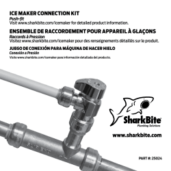
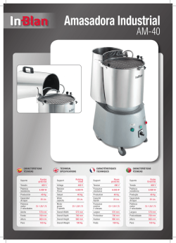
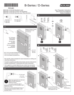
© Copyright 2026