
USER INSTRUCTIONS - Flowserve Corporation
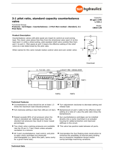
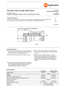
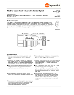
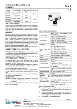
User Instructions Logix 505si - LGENIM0505-00 03/09 ® Logix 505si Series Digital Positioner FCD LGENIM0505-00 03/09 Experience In Motion USER INSTRUCTIONS Installation Operation Maintenance 1 User Instructions Logix 505si - LGENIM0505-00 03/09 ® Table of Content General Information..................................................... Unpacking.................................................................... Logix 505si Overview . ................................................ Specifications............................................................... Principle of Operation.................................................. Tubing.......................................................................... Wiring.......................................................................... Startup......................................................................... Logix 505si Local Interface Operation..................... Operation of Configuration Dipswitch Setup........... Setup of the Cal Dipswitches.................................. Quick-Cal Operation................................................ Factory Reset.......................................................... 2 3 4 4 5 5 6 7 7 7 8 8 8 Error Codes.................................................................. Trouble Shooting.......................................................... Spare parts.................................................................. Dimensions.................................................................. 9 11 12 14 1 Using FLOWSERVE VALVES, ACTUATORS AND ACCESSORIES CORRECTLY 1.1 Using The following instructions are designed to assist in unpacking, installing and performing maintenance as required on FLOWSERVE products. Product users and maintenance personnel should thoroughly review this bulletin prior to installing, operating or performing any maintenance. In most cases FLOWSERVE valves, actuators and accessories are designed for specific applications (e.g. with regard to medium, pressure, temperature). For this reason they should not be used in other applications without first contacting the manufacturer. 1.2 Terms concerning safety The safety terms DANGER, WARNING, CAUTION and NOTE are used in these instructions to highlight particular dangers and/or to provide additional information on aspects that may not be readily apparent. 2 Page DANGER: indicates that death, severe personal injury and/or substantial property damage will occur if proper precautions are not taken. STOP! WARNING: indicates that death, severe personal injury and/or substantial property damage can occur if proper precautions are not taken. CAUTION: indicates that minor personal injury and/or property damage can occur if proper precautions are not taken. NOTE: indicates and provides additional technical information, which may not be very obvious even to qualified personnel. Compliance with other, not particularly emphasised notes, with regard to transport, assembly, operation and maintenance and with regard to technical documentation (e.g. in the operating instruction, product documentation or on the product itself) is essential, in order to avoid faults, which in themselves might directly or indirectly cause severe personal injury or property damage. 1.3 Protective clothing FLOWSERVE products are often used in problematic applications (e.g. extremely high pressures, dangerous, toxic or corrosive mediums). In particular valves with bellows seals point to such applications. When performing service, inspection or repair operations always ensure, that the valve and actuator are depressurised and that the valve has been cleaned and is free from harmful substances. In such cases pay particular attention to personal protection (protective clothing, gloves, glasses etc.). 1.4 Qualified personnel Qualified personnel are people who, on account of their training, experience and instruction and their knowledge of relevant standards, specifications, accident prevention regulations and operating conditions, have been authorised by those responsible for the safety of the plant to perform the necessary work and who can recognise and avoid possible dangers. 1.5Installation DANGER: Before installation check the order-no, serialno. and/or the tag-no. to ensure that the valve/actuator is correct for the intended application. Do not insulate extensions that are provided for hot or cold services. Pipelines must be correctly aligned to ensure that the valve is not fitted under tension. Fire protection must be provided by the user. User Instructions Logix 505si - LGENIM0505-00 03/09 ® 1.6 Spare parts 1.9 Valve and actuator variations Use only FLOWSERVE original spare parts. FLOWSERVE cannot accept responsibility for any damages that occur from using spare parts or fastening materials from other manufactures. If FLOWSERVE products (especially sealing materials) have been on store for longer periods check these for corrosion or deterioration before using these products. Fire protection for FLOWSERVE products must be provided by the end user. 1.7 Service / repair These instructions cannot claim to cover all details of all possible product variations, nor in particular can they provide information for every possible example of installation, operation or maintenance. This means that the instructions normally include only the directions to be followed by qualified personal where the product is being used for is defined purpose. If there are any uncertainties in this respect particularly in the event of missing product-related information, clarification must be obtained via the appropriate FLOWSERVE sales office. To avoid possible injury to personnel or damage to products, safety terms must be strictly adhered to. Modifying this product, substituting nonfactory parts, or using maintenance procedures other than outlined in this instruction could drastically affect performance and be hazardous to personnel and equipment, and may void existing warranties. Between actuator and valve there are moving parts. To avoid injury FLOWSERVE provides pinch-point-protection in the form of cover plates, especially where side-mounted positioners are fitted. If these plates are removed for inspection, service or repair special attention is required. After completing work the cover plates must be refitted. 2 UNPACKING Each delivery includes a packing slip. When unpacking, check all delivered valves and accessories using this packing slip. Report transport damage to the carrier immediately. In case of discrepancies, contact your nearest FLOWSERVE location. Apart from the operating instructions and the obligatory accident prevention directives valid in the country of use, all recognised regulations for safety and good engineering practices must be followed. WARNING: Before products are returned to FLOWSERVE for repair or service FLOWSERVE must be provided with a certificate which confirms that the product has been decontaminated and is clean. FLOWSERVE will not accept deliveries if a certificate has not been provided (a form can be obtained from FLOWSERVE). STOP! 1.8 Storage In most cases FLOWSERVE products are manufactured from stainless steel. Products not manufactured from stainless steel are provided with an epoxy resin coating. This means that FLOWSERVE products are well protected from corrosion. Nevertheless FLOWSERVE products must be stored adequately in a clean, dry environment. Plastic caps are fitted to protect the flange faces to prevent the ingress of foreign materials. These caps should not be removed until the valve is actually mounted into the system. 3 User Instructions Logix 505si - LGENIM0505-00 03/09 ® 3 Logix 505si Overview The Logix 505si is a two-wire, 4-20 mA input digital valve positioner. The Logix 505si positioner controls single-acting actuators with linear and rotary mountings. The Logix 505si is completely powered by the 4-20 mA input signal. The minimum input signal required to function is 3,6 mA. pressure to the actuator’s maximum rating (not to be confused with operating range). A coalescing air filter is recommended for all applications due to the close tolerances in the positioner. NOTE: The air supply must conform to ISA 7.0.01or IEC 770 (a dew point at least 10 ˚C / 18 ˚F below ambient temperature, particle size below five microns – one micron recommended – and oil content not to exceed one part per million). Since the positioner is insensitive to supply pressure changes and can handle supply pressures from 1,5 to 6 barg (22 to 87 psig), a supply regulator is usually not required; however, in applications where the supply pressure is higher than the maximum actuator pressure rating a supply regulator is required to lower the 4 Specifications Table 1: Input Signal Table 5: Shipping Weights Input Signal Range 4 - 20 mA Compliance Voltage 6 VDC Voltage Supply (maximum) 30 VDC Base Positioner without Accessories 1,2 kg (2,65 lbs) Minimum Required Operating 3,6 mA Current Table 6: Performance Characteristics (typical) Table 2: Stroke Output Feedback Shaft Rotation Min. 15°, max 90° 40° recommended for linear applications Linearity < +/- 1,0% Resolution < 0,3% Repeatability < 0,5% Deadband < 0,5% Table 7: Environmental Conditions Table 3: Air Supply Air Supply Quality Free from moisture, oil and dust per IEC 770 and ISA-7.0.01 Input Pressure Range 1,5 to 6,0 bar (22 to 87 psi) Air Consumption (steady state) 0,08 Nm³/h @ 1,5 bar (0,047 SCFM @ 22 psi) 0,12 Nm³/h @ 6,0 bar (0,071 SCFM @ 87 psi) Operating Temperature Standard -20 °C to +80 °C (-4 °F to +178 °F) Operating Temperature Low -40 °C to +80 °C (-40 °F to +178 °F) Transport and Storage Temperature -40 °C to +80 °C (-40 °F to +178 °F) Operating Humidity 0 to 100% non-condensing Table 4: Output Signal 4 Output Pressure Range 0 to 100% of air supply pressure Output Flow Capacity 2,4 Nm³/h @ 1,5 bar (1,41 SCFM @ 22 psi) 7,0 Nm³/h @ 6,0 bar (4,12 SCFM @ 87 psi) Table 8: Hazardous Area Specifications ATEX II 1G Ex ia II C T6 ATEX II 3G Ex nL nA II C T4 User Instructions Logix 505si - LGENIM0505-00 03/09 ® Filter / Regulator for Supply Air 1.5 – 6.0 bar (22 – 87 psi) Air Supply 2 Electro-pneumatic Converter Module 1 Digital Control Circuit Pressure Regulator Inner Loop Piezo Control - + 4 – 20 mA Input Inner Loop Position Feedback MicroProcessor Piezo Valve Pneumatic Amplifier 3 Valve Position Sensor Local User Interface Stroke Control Valve Figure 1: Logix 505si Principle of Operation 5 Principle of Operation The Logix 505si positioner is a basic digital positioner consisting of three main modules: 1. The microprocessor based electronic control module includes direct local user interface switches 2. The piezo valve based electro-pneumatic converter module 3. The infinite resolution valve position sensor. The basic positioner operation is best understood by referring to Figure 1. The complete control circuit is powered by the two-wire, 4-20 mA command signal. The analog 4‑20 mA command is passed to the microprocessor, where it is compared to the measured valve stem position. The control algorithm in the processor performs control calculations and produces an output command to the piezo valve, which drives the pneumatic amplifier. The position of the pilot valve in the pneumatic amplifier is measured and relayed to the inner loop control circuit. This two-stage control provides for more responsive and tighter control than is possible with a single stage control algorithm. The pneumatic amplifier controls the airflow to the actuator. The change of pressure and volume of the air in the actuator causes the valve to stroke. As the valve approaches the desired position, the difference between the commanded position and the measured position becomes smaller and the output to the piezo is decreased. This, in turn, causes the pilot valve to close and the resulting flow to decrease, which slows the actuator movement as it approaches the new commanded position. When the valve actuator is at the desired position, the pneumatic amplifier output is held at zero, which holds the valve in a constant position. 6 Tubing Positioner to Actuator After mounting has been completed, tube the positioner to the actuator using the appropriate compression fitting connectors: Air connections: 1/4” NPT (standard air connection) Auxiliary power: Pressurized air or permissible gases, free of moisture and dust in according with IEC 770 or ISA 7.0.01. Pressure range: 1,5 – 6,0 bar (22 – 87 psi) For connecting the air piping, the following notes should be observed: 1. The positioner passageways are equipped with screws, which remove medium and coarse size dirt from the pressurized air. If necessary, they are easily accessible for cleaning. 2. Supply air should meet IEC 770 or ISA 7.0.01 requirements. A coalescing filter should be installed in front of the supply air connection Z. Now connect the air supply to the filter, which is connected to the Logix 500 Series positioner. 3. With a maximum supply pressure of 6 bar (87 psi) a regulator is not required. 4. With an operating pressure of more than 6 bar (87 psi), a reducing regulator is required. The 5 User Instructions Logix 505si - LGENIM0505-00 03/09 ® Table 10: Connection Table Connection Y Z Description +11 Input+ 4..20 mA -12 Input- 4..20 mA Y (0⇒) Pneumatic output signal (outlet) Z (0⇐) Air supply 4-20 mA Signal Internal Housing EARTH Terminal Shielded Cable Connect Shield at Source Ground 4-20 mA Current Source + Figure 2: Wiring Diagram flow capacity of the regulator must be larger than the flow capacity of the positioner (7 Nm3/h @ 6 bar / 4,12 scfm @ 87 psi). 6 Grounding Screw The grounding screw, located inside the positioner cover, should be used to provide the unit with an adequate and reliable earth ground reference. This ground should be tied to the same ground as the electrical conduit. Additionally, the electrical conduit should be earth grounded at both ends of its run. The grounded screw must not be used to terminate signal shield wires. 5. Connect the outlet connector Y of the positioner to the actuator with tubing, independent of the action (direct or reverse). 7 Wiring and Grounding Guidelines Electrical connections: signal cable with cable passage (NPT or M20 x 1,5) to terminals 2 x 2,5 mm Compliance Voltage (Figure 3) Input signal: 4 – 20 mA NOTE: Observe the minimum requirements of voltage and equivalent electrical load: 6,0 VDC / 300 Ω / at 20 mA The performance is ensured only for a minimum input current of 3,6 mA. Output compliance voltage refers to the voltage limit the current source can provide. A current loop system consists of the current source, wiring resistance, barrier resistance (if present), and the Logix 505si impedance. The Logix 505si requires that the current loop system allow for a 6,0 VDC drop across the positioner at maximum loop current. For wiring, the following notes should be observed: NOTE: The input loop current signal to the Logix 505si should be in shielded cable. Shields must be tied to a ground at only one end of the cable to provide a place for environmental electrical noise to be removed from the cable. In general, shield wire should be connected at the source. (Figure 2) CAUTION: Never connect a voltage source directly across the positioner terminals. This could cause permanent circuit board damage. Connect the 4-20 mA current source to terminals +11 and -12 (Figure 2). User Instructions Logix 505si - LGENIM0505-00 03/09 ® Compliance Voltage 12V 6V Controller Voltage 505si 510 Figure 3: Compliance Voltage In order to determine if the loop will support the Logix 505si, perform the following calculation: Available Voltage = Controller Voltage (@CurrentMAX) - CurrentMAX*(Rbarrier + Rwire) The calculated available voltage must be greater than 6.0 VDC in order to support the Logix 505si. Example: DCS Controller Voltage = 19 V Rbarrier = 300Ω Rwire = 25 Ω CURRENTMAX = 20 mA Voltage = 19 V - 0,020 A*(300Ω + 25 Ω) = 12,5 V The available voltage 12,5 V is greater than the required 6.0 V; therefore, this system will support the Logix 505si. The Logix 505si has an input resistance equivalent to 300 Ω at a 20 mA input current. In the event of a severe electrostatic discharge near the positioner, the device should be inspected to ensure correct operability. It may be necessary to recalibrate the Logix 505si positioner to restore operation. 8 STARTUP 8.1 Logix 505si Local Interface Operation The Logix 505si local user interface allows the user to configure the operation of the positioner, tune the response, and calibrate the positioner. The Local interface consists of a quick calibration button for automatic zero and span setting. There is also a switch block containing 4 switches. For indication of the operational status or alarm conditions there are 3 LEDs on the local user interface. This document describes the setting and use of the Logix 505si user interface. 8.2Initial DIP Switch Setting Before placing the unit in service, set the DIP switches to the desired control options. For a detailed description of each DIP switch setting, see sections below. NOTE: The switch settings except the gain modifier are activated only by pressing the Quick-Cal button. The gain modifier switch is active at all times. a. Operation of Configuration DIP switch Setup Air Action - This must be set to match the configuration of the valve/actuator mechanical tubing connection and spring location since these determine the air action of the system. • ATO (air-to-open)- Selecting ATO if increasing output pressure from the positioner is tubed so it will cause the valve to open. • ATC (air-to-close)- Selecting ATC if increasing output pressure from the positioner is tubed so it will cause the valve to close. The Logix 505si digital positioner has been designed to operate correctly in electromagnetic (EM) fields found in typical industrial environments. Care should be taken to prevent the positioner from being used in environments with excessively high EM field strengths (greater than 10 V/m). Portable EM devices such as hand-held two-way radios should not be used within 30 cm of the device. Ensure proper wiring and shielding techniques of the control lines, and route control lines away from electromagnetic sources that may cause unwanted noise. An electromagnetic line filter can be used to further eliminate noise (FLOWSERVE Part Number 10156843). 7 User Instructions Logix 505si - LGENIM0505-00 03/09 ® Configuration Switches LED Status Lights Quick-Cal Switch 4-20 mA Input Figure 4: Logix 505si Local Interface b. • • Split range - Split range selection is used to limit the action control region to either 4 - 12 mA or 12 - 20 mA. Thisallows two valves to be controled from the same 4 - 20 mA control line. Full: The 505si uses the full 4 - 20 mA range to control the valve. Split: The 505si uses either 4 - 12 or 12 - 20 mA to control the valve. c. 4 - 12 (12 - 4) or 12 - 20 (20 - 12) is used to select the range used for control. This switch is only active when the full/split switch is in the split position. • 4 - 12 (12 - 4) Full valve travel in the 4 - 12 mA range for ATO (12 - 4 mA range for ATC) 12 - 20 (20 - 12) Full valve travel in the 12 - 20 mA range for ATO (20 - 12 mA range for ATC) • high friction levels. This setting slightly slows the response and will normally stop limit cycling that can occur on high friction valves. STOP! 8.3 QUICK-CAL Operation The QUICK-CAL button is used to locally initiate a calibration of the positioner. Pressing and holding the QUICK-CAL button for approximately 3 seconds will initiate the calibration. The settings of all the configuration switches are read and the operation of the positioner adjusted accordingly. A QUICK-CAL can be aborted at any time by briefly pressing the QUICK-CAL button and the previous settings will be retained. While the calibration is in progress you will notice a series of different lights flashing indicating the calibration progress. When the lights return to a sequence that starts with a green light the calibration is complete. (see the section 9 for an explanation of the various light sequences) 8.4 Factory reset Hold Quick cal button while applying power and all of the internal variables including calibration will be reset to factory defaults. The positioner must be re-calibrated after a factory reset. d.Gain Switch – This switch adjusts the position control algorithm of the positioner for standard or low gain. 8 • Standard: Placing the switch to the left opmizes the response for low friction, high performance control valves. This setting provides for optimum response times when used with most low friction control valves. • Low: Placing the switch to the right reduces the gain. It also optimizes the response for valves and actuators with WARNING: During the Quick-Cal operation the valve may stroke unexpectedly. Notify proper personnel that the valve will stroke, and make sure the valve is properly isolated. User Instructions Logix 505si - LGENIM0505-00 03/09 ® 9 STATUS Codes Logix 505si Status Condition Codes Colors G--- Identifier GGGG GGGY 1 2 GGYR Y--- 3 YYYY 4 YYYR 5 YYRR 6 YYRY 7 YRRR 9 YRRY 10 YRYY 12 YRYG 13 YRYR 14 15 YRGY 16 YRGR 17 Indication and resolution Any sequence starting with a Green light flashing first is a normal operating mode and indicates that there are no internal problems. No errors, alerts, or warnings. MPC active - The command is below the 1% command limit for tight shutoff feature. This is a normal condition for a closed valve. To clear the condition, adjust the command signal above the specified MPC value, or disable the feature by moving the Tight Shutoff switch to the off position and recalibrating. LED test mode, Initializing - This sequence should only be visible for 3 sequences when powering up the unit. Any sequence starting with a yellow light indicates that the unit is in a special calibration or test mode, or that there was a calibration problem. Relay not operating during calibration – Most Likely the Air supply is not connected. Could also be due to a bad pneumatic relay, failed electronics, or a loose or bad connector from the electronics to the relay. Command minimum saturated - Calibration error indicating that the 4-20 mA signal corresponding to the minimum command was too low. Adjust the signal to higher range and re-do the calibration. This error may be cleared by briefly pushing the quick-cal button, which will force the positioner to use the parameters from the last good calibration. Command span - Calibration error indicating that the 4-20 mA signal was below the minimum calibration span. The minimum calibration span is 3.0 mA. This error may be cleared by briefly pushing the quick-cal button, which will force the positioner to use the parameters from the last good calibration or if the and buttons are pressed simultaneously the calibrated span will be used even though it is less than the recommended range. may be cleared by briefly pushing the quick-cal button, which will force the positioner to use the parameters from the last good calibration. Command maximum saturated - Calibration error indicating that the 4-20 mA signal corresponding the maximum command was too high. Adjust the signal a lower range and re-do the calibration. This error may be cleared by briefly pushing the quick-cal button, which will force the positioner to use the parameters from the last good calibration. Feedback span - The range of motion of the position feedback arm was too small. Check for loose linkages and/or adjust the feedback pin to a position closer to the follower arm pivot to create a larger angle of rotation. Also check the air supply to make sure the system is properly connected. This error may be cleared by briefly pushing the quick-cal button, which will force the positioner to use the parameters from the last good calibration. Feedback 100 saturated - Calibration error indicating that the position sensor was out of range during the calibration. To correct the condition, adjust the positioner mounting, linkage or feedback potentiometer to move the position sensor back into range then restart the calibration. This error may be cleared by briefly pushing the quick-cal button, which will force the positioner to use the parameters from the last good calibration. Feedback no-motion during calibration - Indicates that there was no motion of the actuator based on the current stroke time configuration. Check linkages and air supply to make sure the system is properly connected. If the time out occurred because the actuator is very large then simply retry the Quick cal and the positioner will automatically adjust for a larger actuator by doubling the time allowed for movement. This error may be cleared by briefly pushing the quick-cal button, which will force the positioner to use the parameters from the last good calibration. Setting IL offset (during Stroke calibration) - An automatic step in the calibration process that is done with the valve a 50% position. This must be completed for proper operation. Feedback 0 saturated - Calibration error indicating that the position sensor was out of range during the valve a 50% position. This must be completed for proper operation. calibration. To correct the condition, adjust the positioner mounting, linkage or feedback potentiometer to move the position sensor back into range then restart the calibration. This error may be cleared by briefly pushing the quick-cal button, which will force the positioner to use the parameters from the last good calibration. Stroke Calibration in Progress - Calibration sequence started using the local quick-cal button. It may be cancelled by briefly pushing the quick-cal button. Unable to set IL offset during QUICK-CAL – This may occur on very large or small actuators on the first calibration attempt. The Logix 505 will automatically adjust parameters for future calibrations. To Continue briefly push the quick-cal button to acknowledge and restart quick-cal. Feedback unstable during calibration - Check for loose linkages or loose positioner sensor. This error may be cleared by briefly pushing the quick-cal button, which will force the positioner to use the parameters from the last good calibration. 9 User Instructions Logix 505si - LGENIM0505-00 03/09 ® Logix 505si Status Condition Codes 10 Colors YGRY Identifier 23 R--RRYY RYYR 25 26 RYRY 27 RGRR 28 Indication and resolution Analog output span too small - The span must be calibrated to a range greater than 3.0 mA. This error may be cleared by briefly pushing the quick-cal button, which will force the positioner to use the parameters from the last good calibration. Any sequence starting with a red light indicates that there is an operational problem with the unit. Piezo voltage - (bad electronic assembly - replace.) Relay not operating – Most Likely the Air supply is disconnected. Could also be due to a bad pneumatic relay, failed electronics, or a loose or bad connector from the electronics to the relay. Relay failed – Could be due to a bad pneumatic relay, failed electronics, or a loose or bad connector from the electronics to the relay. Position Deviation – Indicates that he position has exceeded a fixed 20% error between command and position for a period of time 5 times longer than the recorded stroke time. This error is usually seen when the positioner is first mounted and powered up before a stroke calibration has been done. If the positioner is properly calibrated, the air supply is correct, and the linkage is properly adjusted this error normally indicates that there is a mechanical problem in the positioner, actuator, or valve that is preventing the valve from stroking properly. If a regulated air supply connected to the actuator properly strokes the valve this indicates a bad positioner and should be replaced if a calibration does not clear the error. User Instructions Logix 505si - LGENIM0505-00 03/09 ® 10 TROUBLESHOOTING LOGIX 505SI DIGITAL POSITIONERS Failure Probable Cause Corrective action No LED is blinking 1. Current source below 3.6 mA 2. Incorrect wiring polarity 1. Verify current source is outputting at least 3,6 mA 2. Check wiring for correct polarity Unit does not respond to analog commands 1.Error occurred during calibration 1. Correct calibration error. Recalibrate Valve position reading is not what is expected 1. Stroke not calibrated 2. Stem position sensor mounting is off 180 degrees 1. Recalibrate 2. Orient sensor properly Position is driven fully open or closed and will not respond to command 1. Stroke not calibrated 1. Calibrate valve stroke 2. Inner-loop hall sensor not connected 2. Verify hardware connections 3. Wrong air action set on DIP switch 3. Check ATO (Air-to-open) and ATC (Air-to-Close) settings. Recalibrate 4. Actuator tubing backward 4. Verify ATO/ATC actuator tubing 5. Electro-pneumatic converter 5. Replace electro-pneumatic converter malfunctioning Sticking or hunting operation of the positioner 1. Contamination of the electropneumatic converter. 1. Check air supply for proper filtering and meeting ISA specifcations ISA-7.0.01 2. Control gain set too high 2. Switch to low gain setting 11 User Instructions Logix 505si - LGENIM0505-00 03/09 ® 11 SPARE PARTS KITS Item No. 1 2 Description Cover Assembly Part-No. Yellow 255240.999.000 White 218771.999.000 Black 218772.999.000 PC Board Assembly Logix 505si 255241.999.000 Relay Module Assembly: -20ºC to 85ºC (-4ºF to 185ºF) 230103.999.000 Relay Module Assembly: -40ºC to 85ºC (-40ºF to 185ºF) 218773.999.000 4 Repair kit for Potentiometer Assembly 218774.999.000 5 Position Feedback Assembly 218774.999.000 8 Follower Arm Assembly 3 Max. stroke 65 mm 214323.999.000 Max. stroke 110 mm 214322.999.000 Mounting Kits 12 Description Part-No. – IEC 534 part 6 (Valtek 2000, Kämmer KA, Kämmer KP, and standard NAMUR linear valves) 213619.999.000 – Rotary VDI/VDE 3845 (DIN ISO 5211) 188151.999.000 – Flowserve direct mounting 214004.999.000 – Linear VDI / VDO 3847 255242.999.000 User Instructions Logix 505si - LGENIM0505-00 03/09 ® 1 2 3 4 Fig 5: Exploded drawing for spare parts 13 User Instructions Logix 505si - LGENIM0505-00 03/09 ® Dimensions EXTERIOR GROUNDING SCREW LED WINDOW M20X1,5 OR 1/2" NPT 22.95 .90 G1/4" OR 1/4" NPT FRONT VIEW M8 32.00 1.3 98.14 3.9 10.00 .39 4.00 .2 4.80 .2 "D" SHAFT OPTION (STANDARD) 2.31 .09 174.10 6.85 64.10 2.52 "N" SHAFT OPTION (VDI/VDE 3845, NAMUR) 28.60 1.13 28.60 1.13 53.00 2.09 57.20 2.25 35.40 1.39 17.70 .70 4.00 .2 10.00 .4 17.70 .70 100.00 3.94 M6 35.40 1.39 57.20 2.25 M8X1,25 OR 5/16"-18UNC BACK VIEW Figure 6: Dimensional Drawing of the Logix 500si Series Digital Positioner 14 MM INCH User Instructions Logix 505si - LGENIM0505-00 03/09 FIG. 6 - DIMENSIONAL DRAWING FOR OPTIONS ® SINGLE PRESSURE GAUGE 1/4" NPT 100.00 3.94 216.18 8.51 AUXILIARY OPTIONS - “GA” (GAUGE ADAPTER) TWO PRESSURE GAUGES 100.00 3.94 1/4" NPT 216.87 8.54 AUXILIARY OPTIONS - “GM” (GAUGE MANIFOLD) 47.63 DOMED INDICATOR 1.88 100.00 3.94 63.50 2.50 173.50 6.83 127.69 5.03 POSITION INDICATOR - “D” (DOMED INDICATOR) MM INCH Figure 7: Dimensional Drawing of the Logix 500si for options 15 User Instructions Logix 505si - LGENIM0505-00 03/09 ® Flowserve Headquarters 5215 N. O'Connor Blvd. Suite 2300 Irving, Tx. 75039 Phone: +1 972 443 6500 Flowserve Corporation Flow Control 1350 N. Mt. Springs Parkway Springville, UT 84663 USA Phone: +1 801 489 8611 Fax: +1 801 489 3719 Flowserve (Austria) GmbH Control Valves - Villach Operation Kasernengasse 6 9500 Villach Austria Phone: +43 (0)4242 41181 0 Fax: +43 (0)4242 41181 50 Flowserve Australia Pty Ltd. 14 Dalmore Drive Scoresby, Victoria 311616 Australia Phone: 61 7 32686866 Fax: 61 7 32685466 China 585, Hanwei Plaza 7 Guanghau Road Beijing, China 100004 Phone: +86 10 6561 1900 Contact: Flowserve India Controls Pvt. Ltd Plot # 4, 1A, E.P.I.P, Whitefield Bangalore Kamataka India 560 066 Phone: +91 80 284 10 289 Fax: +91 80 284 10 286 All data subject to change without notice © ©02.2009 Flowserve Corporation. Flowserve and Kämmer are trademarks of Flowserve Corporation 16 Flowserve Essen GmbH Manderscheidtstr. 19 45141 Essen Germany Phone: +49 (0)201 8919 5 Fax: +49 (0)201 8919 662 Flowserve S.A.S. 7, Avenue del la Libération - BP 60 63307 Thiers Cedex France Phone: +33 (0)4 73 80 42 66 Fax: +33 (0)4 73 80 14 24 Flowserve Pte Ltd. 12 Tuas Avenue 20 Singapore 638824 Singapore Phone: 65 6868 4600 Fax: 65 6862 4940 NAF AB Gelbgjutaregatan 2 SE-581 87 Linköping Sweden Phone: +46 (0)13 31 61 00 Fax: +46 (0)13 13 60 54 Kämmer Valves INC. 1300 Parkway View Drive Pittsburgh, Pa 15205 USA Tel.: +1 412 787 8803 Fax: +1 412 787 1944

© Copyright 2026