
Cat HY14-2008 VP120 LS DCV
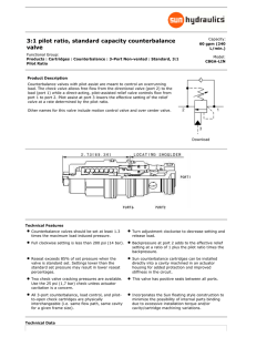
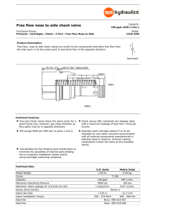
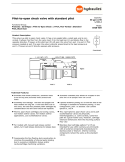
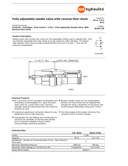
VP120 Load-Sense
Directional Control Valve
Motion Hydraulic Valves
Catalog HY14-2008/US
WARNING – USER RESPONSIBILITY
FAILURE OR IMPROPER SELECTION OR IMPROPER USE OF THE PRODUCTS DESCRIBED HEREIN OR RELATED ITEMS CAN CAUSE DEATH, PERSONAL INJURY AND
PROPERTY DAMAGE.
•
This document and other information from Parker-Hannifin Corporation, its subsidiaries and authorized distributors provide product or system options for further investigation by users having technical expertise.
•
The user, through its own analysis and testing, is solely responsible for making the final selection of the system and components and assuring that all performance, endurance, maintenance, safety and warning requirements of the application are met. The user must analyze all aspects of the application, follow applicable industry standards,
and follow the information concerning the product in the current product catalog and in any other materials provided from Parker or its subsidiaries or authorized distributors.
•
To the extent that Parker or its subsidiaries or authorized distributors provide component or system options based upon data or specifications provided by the user, the user
is responsible for determining that such data and specifications are suitable and sufficient for all applications and reasonably foreseeable uses of the components or systems.
OFFER OF SALE
The items described in this document are hereby offered for sale by Parker-Hannifin Corporation, its subsidiaries or its authorized distributors. This offer and its acceptance
are governed by the provisions stated in the detailed “Offer of Sale” elsewhere in this document or available at www.parker.com/hydraulicvalve.
SAFETY GUIDE
For safety information, see Safety Guide SG HY14-1000 at www.parker.com/safety or call 1-800-CParker.
© Copyright 2013, Parker Hannifin Corporation, All Rights Reserved
Cat HY14-2008-frtcvr.indd, m&a
II
Parker Hannifin Corporation
Hydraulic Valve Division
Elyria, Ohio, USA
Catalog HY14-2008/US
Contents
Load-Sense Directional Control Valve
VP120
Technical Information
General Description.........................................................................................................................................1
Operation..........................................................................................................................................................1
Benefits.............................................................................................................................................................2
Definitions, Conversion Factors......................................................................................................................3
Specifications...................................................................................................................................................4
Weights.............................................................................................................................................................4
Connections.....................................................................................................................................................4
Performance Curves.................................................................................................................................... 5-6
Major Valve Options.........................................................................................................................................7
Schematic Circuit Types..................................................................................................................................8
Dimensions................................................................................................................................................. 9-10
Ordering Information
How to Configure a Valve Assembly.............................................................................................................11
Inlet Attributes.......................................................................................................................................... 12-13
Outlet Attributes.............................................................................................................................................14
Work Sections.......................................................................................................................................... 15-19
Special Inlets/Outlets............................................................................................................................... 20-21
Accessories
Stud Assemblies.............................................................................................................................................22
Assembly Configuration Form ............................................................................................................................23
Terms of Sale with Warranty Limitations ..........................................................................................................24
Safety Guide . ................................................................................................................................................. 25-26
cat hy14-2008/US.indd, m&a
III
Parker Hannifin Corporation
Hydraulic Valve Division
Elyria, Ohio, USA
Catalog HY14-2008/US
Technical Information
Load-Sense Directional Control Valve
VP120
General Description
The VP120 can be configured either as pressurecompensated load-sense (PCLS) or as load-sense
(LS). Both have the flexibility of sectional construction.
The PCLS work section has its own compensator, so
that speed control of multiple functions is achieved,
regardless of changes in pressure or engine rpm’s.
The key technology integrated into the VP120 is
flow-sharing. In pump over-demand conditions, flowsharing benefits machine productivity by maintaining
the speed relationship of the selected functions, but at
a reduced speed. Thus, the operator can maintain the
rhythm of the machine.
A new technology available in the VP120 is
pressure-limiting. This feature allows for selected
functions to operate at pressures lower than loadsense relief-valve setting. The advantage of using
pressure limiters to accomplish this vs. port reliefvalves is that less flow is lost – which means less
heat generation.
The VP120 uses the same port accessories, loadsense relief valve and pressure-reducing valve that
are used in our other valves. The standard spool
types are 3-way, 4-way and 4-position float. A full
range of flow limited spools are available.
Another new technology developed for the VP120
is margin control, which can be used to selectively
boost or reduce the flow out of a work-section.
The combination inlet/outlet can be installed on both
ends of the valve, facilitating the routing of pump
flow to both ends of the valve.
Operation
The VP120 (PCLS) is an individually pressurecompensated load-sense valve. For optimum
horsepower utilization, it is normally used with a
piston pump. However, it does have the flexibility
to be interfaced with a fixed (gear or vane)
displacement pump.
The valve can be operated manually, hydraulicremote and with solenoids. The same solenoid
is used for on/off and proportional control. A
bypass compensator is available for use with fixed
displacement pumps. Also, priority flow control is
an option for steering requirements. In addition,
low pressure regeneration is an option designed
to overcome the damaging affects of cavitation –
namely premature component wear and spongy
operation.
During single function use, the pump control will
determine the flow to the valve, based upon the
area opening of the spool notch and the load-sense
signal being sent back to the pump.
During multi-function operation, the pump control
will determine the flow for the highest loaded
function, while the work-section compensator will
control the flow for the lighter loaded function.
cat hy14-2008/US.indd, m&a
1
Parker Hannifin Corporation
Hydraulic Valve Division
Elyria, Ohio, USA
Load-Sense Directional Control Valve
VP120
Catalog HY14-2008/US
Technical Information
LS checks
[16] Load-sense relief
Compensator assembly
[20] Top outlet port
Clipper relief [31]
[21] Side outlet port
Top & Side HP port [35, 36]
LS to pump port
LS gage port
LS vent
[19] Side inlet port
Top & Side outlet port [37, 38]
[18] Top inlet port
[15] Combo inlet
Combo outlet [30]
Mounting hole
Benefits
• Excellent machine controllability – individual pressure
• Enhanced speed control – the optional margin control
compensation in each work section delivers predictable
metering with single and multi-function operation;
regardless of changed in pressure and input flow. This
enhances machine control, improves productivity and
helps to make every operator an “expert” operator – all
of which saves money. This valve type also lends itself
to closed-loop control.
boosts or reduces flow of the selected work sections.
This enables the hydraulic circuit designer to better
utilize the available pump flow and possibly reduce the
size of the engine.
• Reduced heat generation – pressure limiting is a
feature not common on valves with flow sharing
technology. This feature allows for selected functions
to operate at a pressure less than the setting of the
load-sense relief-valve, while only passing a few liters
of oil to tank. The alternative method for achieving this
is with a port relief-valve. But they can pass anywhere
from 75 LPM (20 GPM) to full flow to tank.
• Improved system efficiency – optimized horsepower
utilization and heat management are features that
are inherent with load-sense pressure-compensated
valves due to a closer match between horsepower
consumption and horsepower demand. Fuel savings
of up to 30% can be achieved vs. open-center type
systems. Also, better horsepower utilization may
enable the use of a smaller engine or elimination of a
heat exchanger.
• Flexible design – the VP120 is available as a pressurecompensated load-sense valve (PCLS) or just as
a load-sense (LS) valve. The combination inlet/out
casting can be installed on both ends of the valve,
which means that pump flows can be routed to both
ends of the valve.
• Enhanced machine productivity – the VP120
incorporates flow-sharing technology. This means that
during a pump over-demand condition the valve will
automatically apportion the available flow to the selected
functions, based upon the area openings of the spool
notches. The selected functions will maintain their speed
relationship, but at a lower overall speed. This automatic
adjusting by the valve can improve machine productivity
as much as 20% and reduce operator fatigue.
• Ease of service – the load-sense check and the
compensator are located on the top of the work
section, making them accessible for trouble-shooting
without having to disassemble the valve bank.
cat hy14-2008/US.indd, m&a
2
Parker Hannifin Corporation
Hydraulic Valve Division
Elyria, Ohio, USA
Catalog HY14-2008/US
Technical Information
Load-Sense Directional Control Valve
VP120
Definitions
PCLS = Pressure Compensated Load-Sense, or
load-sensing with pressure compensation.
FLO = Flow Limit Orifice, limits flow over LSRV.
Normally it is .045" diameter.
LS = Load-Sensing.
Over-demand = When functions demand flow in
excess of pump capacity.
LSRV/PLM = Load-Sense Relief Valve – normally a
small RV that sets maximum LS pressure.
EH = Electrohydraulic or solenoid controlled spool
positioning.
Clipper RV/PA = “Clips” or reduces pressure spikes
normally caused when flow demand decreases
faster than the pump flow output can decrease.
Induced load = Occurs when an actuator tries to
force fluid into a valve workport.
Marginvalve = Pressure at valve inlet – pressure at
valve LS port = Mv.
Pressure Limiting = Port pressure is limited to a
value less than the normal operating pressure. Flow
loss during flow limiting is <2 LPM (.53 GPM).
Marginpump = Pressure at pump outlet – pressure at
pump LS port = Mp.
PBL = Special Option - priority flow, bypass unloader, low pressure regen.
Marginneutral = Mv or Mp when all valve spools are in
neutral.
Marginstall = Mv or Mp when one valve function is
deadheaded and the LSRV relieves.
Conversion Factors:
1 kg = 2.2 lbs.
1N
= 0.225 lbs. force
1 Bar = 14.5 PSI
1 liter = 0.22 UK gallon
1 liter = 0.264 US gallon
1 cm3 = 0.061 in3
1m
= 3.28 feet
1 mm = 0.039 inches
9/5 °C + 32 = °F
Simple outlet
cat hy14-2008/US.indd, m&a
3
Parker Hannifin Corporation
Hydraulic Valve Division
Elyria, Ohio, USA
Load-Sense Directional Control Valve
VP120
Catalog HY14-2008/US
Technical Information
Specifications
Pressures
Flow Rates
Maximum Input: 160 LPM (42 US GPM)
Maximum Flow out of Service Ports:
120 LPM (32 US GPM)
Leakage
Performance
With mineral
oil, 100 SUS
@ 120°F
at 1100 PSI
differential
Workport w/Steel Plug or no Accessory:
20 cc/min max.
Thru Compensator Only:
1100 cc/min max.
Hydraulic
Fluid
Mineral base oil.
For other fluids consult factory.
Viscosity, working range:
15-380mm2/s (15-380 cSt).
Hydraulic Oil
Temperature
Recommended Operating Range
without Solenoid Operation:
-30° to 90°C (-22° to 194°F)
Recommended Operating Range
with Solenoid Operation:
-20° to 80°C (-4° to 176°F)
Filtration
(ISO 4406)
Mounting Surface
Pump inlets: 280 Bar (4060 PSI)
Service Ports: 320 Bar (4640 PSI)
Pilot-EH (input or internal supply):
35 Bar (508 PSI)
Tank Return: 15 Bar (220 PSI)
Solenoid Drain: 2 Bar (29 PSI)
Pilot-Hydraulic Remote: 7-28 Bar
(100-400 PSI)
There is no restriction on orientation.
Flatness should be at least 0.5 mm (0.020")
Surface must be stable and not put stress on valve.
Connections
O-ring boss ports SAE-J1926-1
BSPP ports ISO 1179-1
Pump gage port standard
O-ring boss 9/16"-18 UNF, BSPP ports 1/4"-19
Thread Size
O-ring Boss
BSPP
Description
SAE #
(UNF)
3/ "-14
inlet, top
12
11/16-12
4
1
3/ "-14
inlet, side
12
1 /16-12
4
9/ -18
1/ "-19
EH inlet, pilot
6
16
4
3/ "-14
outlet, top
12
11/16-12
4
1"-11
outlet, side
16
15/16-12
3/ -12
(none)
work section
8
4
7/ -14
1/ "-14
work section
10
8
2
Solenoid Specifications
Voltage
Pilot
20/18/14 in Main Flow Paths
18/16/13 Pilot Supply
Current Input (I)
Weights
Current (mA)
for Spool Shift
Inlets/Outlets
Std. Combination Inlet/Outlet
4.58 kg (10.1 lb)
EH Combination Inlet/Outlet
15.81 kg (12.8 lb)
Combination Inlet/Outlet with
priority flow divider
6.89 kg (15.2 lb)
Combination Inlet/Outlet with
bypass compensator
6.94 kg (15.3 lb)
Combination Inlet/Outlet with low
pressure regeneration
6.85 kg (15.1 lb)
Simple turnaround cover
3.1 kg (6.8 lb)
Insulation Material
Duty Cycle
R20 Ohm
Fluid Cleanliness
Ambient Temperature
Fluid Temperature
12 or 24 VDC
35 Bar (508 PSI),
15-23 LPM (4-6 GPM)
1.5A for 12 VDC
0.75A for 24 VDC
12V
24V
Start Shift
500
250
Full Shift
1250 625
Class H
100%
5.3 (±5%) for 12 VDC
21.2 (±5%) for 24 VDC
17/14 per ISO 4406
-30° to 80°C (-22° to 176°F)
-20° to 80°C (-4° to 176°F)
Work Sections
Manual with 2 port access.
4.17 kg (9.2 lb)
Hydraulic Remote with 2 port access. 4.58 kg (10.1 lb)
EH with 2 port access.
6.03 kg (13.3 lb)
cat hy14-2008/US.indd, m&a
4
Parker Hannifin Corporation
Hydraulic Valve Division
Elyria, Ohio, USA
Load-Sense Directional Control Valve
VP120
Catalog HY14-2008/US
Performance Curves
Compensator Performance
Bar PSI
310 4500
276 4000
34 500
138 2000
103 1500
Reduced Pressure
172 2500
25 GPM Load
207 3000
ad
16 GPM Lo
5 GPM Load
Delta P (LS-Tank)
241 3500
69 1000
34
PRRV Pressure vs. Flow
Bar PSI
38 550
31 450
28 400
24 350
21 300
17 250
500
0
GPM 0
LPM
14 200
5
19
10
38
15
57
20
76
25
95
30
114
GPM 0
LPM
1
2
3
4
5
6
4
8
11
15
19
23
Workport Flow
Flow
1 Spool Pressure Drop vs. Flow
Bar PSI
55 800
10 Spool Pressure Drop vs. Flow
Bar PSI
55 800
Outlet Pump Port to Workport B
48 700
41 600
41 600
Pressure Drop
Pressure Drop
Inlet Pump Port to Workport B
48 700
34 500
28 400
21 300
14 200
0
GPM 0
LPM
10
38
20
76
30
114
40
151
28 400
21 300
14 200
Workport Port A
Return to Inlet Tank Port
7 100
34 500
Workport Port A Return to
Outlet Tank Port
7 100
50
189
0
GPM 0
LPM
60
227
10
38
20
76
40
151
50
189
Flow
Flow
Roughly equivalent when plumbed to Inlet P and T Ports
Roughly equivalent when plumbed to Outlet P and T Ports
10
38
oo
Sp
ed S
32
GP
24 G
M
PM
Ra
ted
Rat
ted S
PM R
a
18 G
14 200
10 150
GPM 0
LPM
l
poo
l
pool
Spool
Rated
12 GPM
17 250
8 GPM Rate
4 GPM Rated Spool
21 300
d Spool
Effects of Margin Pressure
on Flow Output*
Bar PSI
24 350
Margin Pressure
30
114
20
76
30
114
40
151
Flow
* assumes no Delta P from pump to valve
cat hy14-2008/US.indd, m&a
5
Parker Hannifin Corporation
Hydraulic Valve Division
Elyria, Ohio, USA
60
227
Load-Sense Directional Control Valve
VP120
Catalog HY14-2008/US
Performance Curves
A/C Curve
Bar PSI
21 300
300 4351
Workport Pressure
Pressure Drop
17 250
14 200
10 150
7 100
3
Port Relief Valve Curves
Bar PSI
350 5076
50
250 3626
200 2901
150 2176
100 1450
50
0
GPM 0
LPM
10
38
20
76
30
114
40
151
50
189
725
0
GPM 0
LPM
60
227
5
20
11
40
Flow
121
32
106
28
106
28
91
24
91
24
76
20
76
20
61
16
61
16
45
12
45
12
30
8
30
8
15
4
15
4
32 GPM Rated Spool
Workport Flow
Workport Flow
LPM GPM
136
36
32
121
24 GPM Rated Spool
18 GPM Rated Spool
12 GPM Rated Spool
8 GPM Rated Spool
4 GPM Rated Spool
0
inch 0
mm
0.05
1.27
0.1
2.54
0.15
3.81
21
80
26
100
Flow
Meter-In Flow to Workport for
Manually Operated Work Sections
LPM GPM
136
36
16
60
0.2
5.08
0.25
6.35
32 GPM Rated Spool
0
PSI 0
Bar
0.3
7.62
Meter-In Flow to Workport for Hydraulic
Remote Operated Work Sections
24 GPM Rated Spool
18 GPM Rated Spool
12 GPM Rated Spool
8 GPM Rated Spool
4 GPM Rated Spool
50
3
100
7
150
10
200
14
250
17
300
21
Endcap Pressure
Spool Stroke
cat hy14-2008/US.indd, m&a
6
Parker Hannifin Corporation
Hydraulic Valve Division
Elyria, Ohio, USA
350
24
Load-Sense Directional Control Valve
VP120
Catalog HY14-2008/US
Technical Information
Major Valve Options
I Circuits:
A) LS – when individual pressure compensation isn’t needed.
B) PCLS with compensator. Also, both types of valves contain the load check which serves as a low leak
transition check or when “induced loads”* are anticipated.
* Induced loads are actuators trying to force fluid back into valve.
II Inlets:
A) Combo – all spool operators. This also has the option for an external pilot supply in port if there is pilot
supply available external to the valve for the solenoids.
B) “EH” – “external supply” to solenoids – port for connecting external supply to solenoids and drain port.
• Internal supply – reduced PSI to solenoids via internal pilot gallery
internal supply to solenoid operators.
• Joystick supply – reduced PSI to external port to supply joystick(s)
No internal pilot supply.
• Kidney loop – reduced PSI to an external pilot port. The pilot flow can then be routed to
a filter and back into the valve. The signal is then routed to the solenoids via internal pilot
gallery.
All 3 options have: a) PRRV and screen upstream of it
b) Accumulator port and check valve
c) Drain port for connection of solenoid drains and PRRV spring to tank – 2 Bar (29 PSI) max
cat hy14-2008/US.indd, m&a
7
Parker Hannifin Corporation
Hydraulic Valve Division
Elyria, Ohio, USA
Load-Sense Directional Control Valve
VP120
Catalog HY14-2008/US
Schematics
How VP120 May Be Arranged
LSRV/PLM [16]
Clipper RV/PA [26]
Load-Sense Valve
Pressure Compensated Load-Sense (PCLS)
cat hy14-2008/US.indd, m&a
8
Parker Hannifin Corporation
Hydraulic Valve Division
Elyria, Ohio, USA
Load-Sense Directional Control Valve
VP120
Catalog HY14-2008/US
Dimensions
VP120 with Combination Inlet / Combination Outlet
Inch equivalents for millimeter dimensions are shown in (**)
49.6
(1.95)
44.9
(1.77)
No. Of Sections
L1
mm [inch]
L2
mm [inch]
1
72.8 [2.87]
122.8 [4.83]
2
110.9 [4.37]
160.9 [6.33]
40.1
(1.58)
132.5
(5.21)
151.4 (5.96)
111.7 (4.40)
89.7 (3.53)
54 (2.13)
8.7
(.34)
3
149 [5.87]
199.0 [7.83]
4
187.1 [7.37]
237.1 [9.33]
5
225.2 [8.87]
275.2 [10.83]
6
263.3 [10.37]
313.3 [12.33]
7
301.4 [11.87]
351.4 [13.83]
8
339.5 [13.37]
389.5 [15.33]
9
377.6 [14.87]
427.6 [16.83]
10
415.3 [16.37]
465.7 [18.33]
89.7 (3.53)
54 (2.13)
16.3
(.64)
73.4
(2.89)
3.2 (.12)
39.7
(1.56)
38.1
(1.50)
L1
L2
38.1
(1.50)
39.5
(1.56)
3.2 (.12)
PORT B
14.3
(.56)
54 (2.13)
129.8 (5.11)
144.3 (5.68)
PORT A
9.1
(.36)
57.6
(2.27)
54 (2.13)
89.7 (3.53)
144.3 (5.68)
120.7
105.2 (4.75)
(4.14)
79.8
(3.14)
44.9
(1.77)
20.6
(.81)
124.2
(4.89)
126.7
(4.99)
40.1
(1.58)
11.1 (.44)
11.1 (.44)
cat hy14-2008/US.indd, m&a
9
Parker Hannifin Corporation
Hydraulic Valve Division
Elyria, Ohio, USA
Load-Sense Directional Control Valve
VP120
Catalog HY14-2008/US
Dimensions
VP120 with Combination Inlet / Simple Outlet
Inch equivalents for millimeter dimensions are shown in (**)
No. Of Sections
L1
mm [inch]
L2
mm [inch]
1
70.4 [2.77]
108.9 [4.29]
2
108.5 [4.27]
147.0 [5.79]
3
146.6 [5.77]
185.1 [7.29]
4
184.7 [7.27]
223.2 [8.79]
5
222.8 [8.77]
261.3 [10.29]
6
260.9 [10.27]
299.4 [11.79]
7
299.0 [11.77]
337.5 [13.29]
8
337.1 [13.27]
375.6 [14.79]
9
375.2 [14.77]
413.7 [16.29]
10
413.3 [16.27]
451.8 [17.79]
122.1
(4.81)
111.7 (4.40)
151.4 (5.96)
89.7 (3.53)
101.6 (4.00)
30.9 (1.22)
38.1 (1.50)
L1
38.1 (1.50)
L2
39.5
(1.56)
3.2 (.12)
PORT B
14.3
(.56)
54 (2.13)
129.8 (5.11)
144.3 (5.68)
PORT A
9.1
(.36)
57.6
(2.27)
54 (2.13)
89.7 (3.53)
144.3 (5.68)
120.7
105.2 (4.75)
(4.14)
79.8
(3.14)
44.9
(1.77)
124.2
(4.89)
126.7
(4.99)
40.1
(1.58)
11.1 (.44)
11.1 (.44)
cat hy14-2008/US.indd, m&a
10
Parker Hannifin Corporation
Hydraulic Valve Division
Elyria, Ohio, USA
20.6
(.81)
Catalog HY14-2008/US
Ordering Information
Load-Sense Directional Control Valve
VP120
How to Configure a Valve Assembly
There are three choices available to configure a valve assembly: a hard copy specification sheet that is shown
on page 23, an MS Excel spreadsheet version of this specification sheet and an eConfigurator that is web based.
Please contact your Parker representative or local distributor for additional information regarding these options.
All of these choices involve selecting attributes or features for the system – inlet, work section and outlet.
Each of the attributes is associated with a number or position that is shown in brackets [ ].
System Related Attributes
[Position]
Codes
Description
[01]
Valve Type
PCLS
Pressure-compensated load-sense
LS
Load-sense
[04]
Port Type
U
UNF
G
BSPP
[05]
System Voltage
12
12 VDC
24
24 VDC
[06]
Connector Type
D
Deutsch
A
Amp
W
Weatherpack
[07]
Surface Treatment
X
No Paint
P
Black
[08]
Customer Designated ID (pt no)
ID
Enter part number
Note: A jumper is available, Part 391 1823 417, that
will connect a solenoid with an AMP connector to a
Weatherpack connector on a machine.
cat hy14-2008/US.indd, m&a
11
Parker Hannifin Corporation
Hydraulic Valve Division
Elyria, Ohio, USA
Catalog HY14-2008/US
Ordering Information – Inlet
Load-Sense Directional Control Valve
VP120
Inlet Attributes
The standard inlet has high pressure P pump ports available on the top and side, low pressure T tank ports
on the top and side. There are also external LS in port, LS out port and a gage port located on the side. An
optional load-sense relief valve is positioned on the end and set @ 8 lpm (2 GPM).
• Standard – used with all spool operators, except solenoid.
• EH – this is the standard inlet and has machining for external pilot/drain. It also supplies internal pilot
pressure to the work-sections. This also has a screen upstream of the PRRV, an accumulator port and
check valve, a PRRV and a dedicated solenoid drain port.
[15]
IC
IEH
ICF
IPR
ILP
Inlet Section Type
Combo Inlet
EH Combo Inlet
Bypass Inlet
Priority Inlet
Low Pressure Regeneration Inlet
[16]
Y
PA
Load-Sense RV Cavity
Steel plug
RV+AC (non-adjustable)
[17]
Load-Sense RV Setting (2600-4060 psi)
[18]
1TOPB
1TOP
Top Inlet HP Port
SAE 12 or 3/4” BSPP with a steel plug
SAE 12 or 3/4” BSPP open
[19]
1SB
1S
Side Inlet HP Port
SAE 12 or 3/4” BSPP with a steel plug
SAE 12 or 3/4” BSPP open
[16] LSRV Cavity
Code LSRV
Code Y
[20]
Top Outlet LP Port
1 TOPTB SAE 12 or 3/4” BSPP with a steel plug
1 TOPT
SAE 12 or 3/4” BSPP open
[21]
1STB
1ST
Side Outlet LP Port
SAE 16 or 1” BSPP with a steel plug
SAE 16 or 1” BSPP open
[22]
LSP
LSPCK
LSPB
External LS in Cavity
SAE 6 LS in port
SAE 6 LS in port with Check
No LS in port
[23]
PSP
PSPB
External Pilot in Cavity
SAE 6 External Pilot Supply in port
No Pilot Supply in port
cat hy14-2008/US.indd, m&a
12
Parker Hannifin Corporation
Hydraulic Valve Division
Elyria, Ohio, USA
Catalog HY14-2008/US
Ordering Information – Inlet
Load-Sense Directional Control Valve
VP120
[15] Inlet Section Type
Standard Inlet
EH Inlet / Outlet
cat hy14-2008/US.indd, m&a
13
Parker Hannifin Corporation
Hydraulic Valve Division
Elyria, Ohio, USA
Catalog HY14-2008/US
Ordering Information – Outlet
Load-Sense Directional Control Valve
VP120
Outlet Attributes
The outlet is available with low pressure ports (top & side), a load-sense relief valve, load-sense and gage ports
and an optional port to accept a load-sense signal from an external load-sense valve.
[30]
O
OC
OEH
OCF
OPR
OLP
Outlet Section Type
Simple Outlet
Combo Outlet
EH Combo Outlet
Bypass Outlet
Priority Outlet
Low Pressure Regeneration Outlet
[31]
Y
PA
Clipper RV Cavity
Steel plug
RV+AC (non-adjustable)
[32]
Clipper RV Setting
[35]
1TOPB
1TOP
Top Inlet HP Port
SAE 12 or 3/4” BSPP with a steel plug
SAE 12 or 3/4” BSPP open
[36]
1SB
1S
Side Inlet HP Port
SAE 12 or 3/4” BSPP with a steel plug
SAE 12 or 3/4” BSPP open
[31] Clipper RV Cavity
Code Y
PRESSURE SETTING Bar (PSI)
25 (363)
32 (464)
40 (580)
50 (725)
63 (914)
80 (1160)
100 (1450)
125 (1813)
140 (2030)
160 (2320)
175 (2538)
190 (2755)
210 (3045)
230 (3335)
250 (3625)
280 (4060)
300 (4350)
330 (4785)
350 (5075)
380 (5510)
400 (5800)
420 (6090)
260 (3770)
270 (3915)
225 (3263)
[37]
Top Outlet LP Port
1TOPTB SAE 12 or 3/4” BSPP with a steel plug
1TOPT
SAE 12 or 3/4” BSPP open
[38]
1STB
1ST
Code PA
Side Outlet LP Port
SAE 16 or 1” BSPP with a steel plug
SAE 16 or 1” BSPP open
Combination Outlet
Outlet Simple
cat hy14-2008/US.indd, m&a
14
Parker Hannifin Corporation
Hydraulic Valve Division
Elyria, Ohio, USA
Catalog HY14-2008/US
Ordering Information – Work Sections
Load-Sense Directional Control Valve
VP120
Work Section Attributes
Work sections are available in 3-way, 3-position (cylinder & motor), a 4-way, 3-position (cylinder & motor), and
a 4-position float. There are six flow ranges available for each spool type. These spools are based upon a valve
margin pressure of 17 Bar (250 PSI). Spool positioners are manual, hydraulic remote and solenoid.
Load-Sensing Work Section
work ports
Load-sense check
B
A
spool positioner
Load-sense
check
Transition
check
Transition check
PCLS Work Section with Transition Check
Load-sense check
work ports
Compensator
A
B
Compensator
Compensator
Orifice
Transition check
Work Section Attributes
[47]
WP2001
Size of Work Ports
SAE 10 or 1/2" BSPP
[50]
C1
PC
EC
ECS
ECH/ECFH
PCF
ECF
Spool Positioner (See below and next page)
Manual, 3 position
Hydraulic-remote, 3 position
Solenoid, 3 position
Electrohydraulic without override
Electrohydraulic with handle option
Hydraulic-remote, 4th position float
EH 4th position float
cat hy14-2008/US.indd, m&a
15
Parker Hannifin Corporation
Hydraulic Valve Division
Elyria, Ohio, USA
Catalog HY14-2008/US
Ordering Information – Work Sections
Load-Sense Directional Control Valve
VP120
[50] Work Section Spool Positioner
Code C1 = Spring Return
Basic Function:
Return spool to neutral position from either work position when handle is released. Manual handle operation.
[50] Work Section Spool Positioner
Code PC = Hydraulic Remote (Proportional)
Code EC = Proportional Solenoid, 3-Position
Basic Function:
Proportional hydraulic pilot PSI is admitted to port
(PCL4) and balances against metering/return springs.
Use metering band of PCL4 for best match.
Basic Function:
Proportional spool movement via proportional current
to solenoid (ref. IQAN).
Pilot Hyd.
PSI Supply
[51]
L1
L2
Manual Operator (See next page)
Type 1 with Handle Bracket
Type 2 Lug End Only
[55A]
Solenoid pilot orifice. Controls shift to ‘A’ port – mm.
This option is utilized when dampening is needed.
The standard size is 2mm.
[55B]
Solenoid pilot orifice. Controls shift to ‘B’ port – mm.
This option is utilized when dampening is needed.
The standard size is 2mm.
Pilot Hyd.
PSI Supply
cat hy14-2008/US.indd, m&a
16
Parker Hannifin Corporation
Hydraulic Valve Division
Elyria, Ohio, USA
Catalog HY14-2008/US
Ordering Information – Work Sections
Load-Sense Directional Control Valve
VP120
Manual Operators
Type 1 Handle End
Type 2 Lug End
Inch equivalents for millimeter dimensions are shown in (**)
cat hy14-2008/US.indd, m&a
17
Parker Hannifin Corporation
Hydraulic Valve Division
Elyria, Ohio, USA
Catalog HY14-2008/US
Ordering Information – Work Sections
Load-Sense Directional Control Valve
VP120
[60]
Spool Function
D
Double-Acting Cylinder
M
Double-Acting Motor
DEB
Single-Acting Cylinder @ port B
MEB
Single-Acting Motor @ port B
F
4th Position Float
Please consult factory for availability
[72A]
LPM
Flow setting out of port ‘A’ with stroke limiter. For hydraulic remote or solenoid operation.
Enter setting
[72B]
LPM
Flow setting out of port ‘B’ with stroke limiter. For hydraulic remote or solenoid operation.
Enter setting
[69]
15/4
30/8
45/12
68/18
90/24
120/32
Spool Flow at Full Stroke – Ports ‘A & B’. This is based upon a margin pressure of 17 Bar (250 PSI)
15 LPM (4 GPM)
30 LPM (8 GPM)
45 LPM (12 GPM)
68 LPM (18 GPM)
90 LPM (24 GPM)
120 LPM (32 GPM)
This spool will meter to approximately 75% of stroke.
With further spool movement, the spool will come off the notch.
B A
B A
B A
B A
Full
B A
cat hy14-2008/US.indd, m&a
18
Parker Hannifin Corporation
Hydraulic Valve Division
Elyria, Ohio, USA
Catalog HY14-2008/US
Ordering Information – Work Sections
Load-Sense Directional Control Valve
VP120
Workport Accessories – Select one for each port
Port A
[76A]
N2
Y2
25
32
40
50
63
80
100
125
140
160
175
190
210
225
230
250
265
270
280
300
330
350
380
400
420
Port B
Description
Anticavitation check
Steel Plug
25 bar (363 PSI)
32 bar (464 PSI)
40 bar (580 PSI)
50 bar (725 PSI)
63 bar (914 PSI)
80 bar (1160 PSI)
100 bar (1450 PSI)
125 bar (1813 PSI)
140 bar (2030 PSI)
160 bar (2320 PSI)
175 bar (2538 PSI)
190 bar (2755 PSI)
210 bar (3045 PSI)
225 bar (3263 PSI)
230 bar (3335 PSI)
250 bar (3625 PSI)
265 bar (3843 PSI)
270 bar (3915 PSI)
280 bar (4060 PSI)
300 bar (4350 PSI)
330 bar (4785 PSI)
350 bar (5075 PSI)
380 bar (5510 PSI)
400 bar (5800 PSI)
420 bar (6090 PSI)
[76B]
N2
Y2
25
32
40
50
63
80
100
125
140
160
175
190
210
225
230
250
265
270
280
300
330
350
380
400
420
[76A] and [76B] – Workport Accessories
Relief with Anticavitation Check
Code Y2 – Relief Cavity Plug
Code N2 – Anticavitation Check
cat hy14-2008/US.indd, m&a
19
Parker Hannifin Corporation
Hydraulic Valve Division
Elyria, Ohio, USA
Load-Sense Directional Control Valve
Ordering Information – Special Inlets/Outlets VP120
Catalog HY14-2008/US
Margin Control
Please consult factory for availability
Flow Boost or Reduction
Fast winch up or slow track traverse speed
• Flow boost facilitates quickly raising an unloaded
winch hook to a higher elevation
• Slowing track speed to make more flow available
to boom, arm, and bucket functions is a benefit of
flow reduction
Novice vs. Expert Control
Mini-excavator operation
• Pressure gain control + margin control work
together to assist a novice operator with more
forgiving operation. For the novice, margin
control will limit the machine’s maximum function
speed while pressure gain control cushions the
fast reaction of machine controls. As a result, the
mini-excavator is suitable for either the novice or
expert operator.
Deactivation
Disabling a machine function
• A machine may need one or more functions
disabled for safety during a certain sequence of
operations.
Speed Sensing Power Control
Horsepower limitation
• Horsepower can be managed by reducing flow to
certain or all functions during a machine cycle.
Hydraulic Cylinder damping
Programmed damping mode
• Automatic cylinder speed ramp down near the
end of stroke extends the component and overall
machine life.
Priority
Wheel loader operation
• Margin control can automatically give boom raise
priority over bucket rollback.
Pressure Flow Limitation (PLQ)
Please consult factory for availability
Scraping with plow
• Regulated pressure is required to control the force
of the plow blade against the ground.
General Application Concept
Constant force or torque
• Any application that requires a constant force
or torque via deadheading a workport can use
PLQ. This assumes the PLQ regulated workport
pressure is less than maximum system pressure.
The PLQ work section only consumes a very
insignificant flow of less than 0.75 gpm. Working
at only the essential pressure and minimum flow
maximizes energy efficiency.
Forestry - Log Skidder and Log Loader
Clamping and retaining logs
• Regulated pressure is required to control the
clamping force of the tongs against the logs while
they are being moved.
Stamping, Molding Machines
Maximum press
• Regulated pressure is required to control the force
of a ram against the part being made.
Snow Plow Salt Spreader Truck
Plow blade elevation
• Regulated pressure is required to generate upward
force to counter gravity acting on the blade in order
to maintain elevation.
cat hy14-2008/US.indd, m&a
20
Parker Hannifin Corporation
Hydraulic Valve Division
Elyria, Ohio, USA
Load-Sense Directional Control Valve
Ordering Information – Special Inlets/Outlets VP120
Catalog HY14-2008/US
Swing Stability
Low Pressure Regeneration
(Available as Inlet or Outlet Section)
Please consult factory for availability
Load-sense signal conditioning
Winch stability
• Encourages the actuator to maintain a velocity
which minimizes instability during initial function
movement by creating an artificial load-sense
signal greater than the actual load pressure.
Please consult factory for availability
Cavitation
To combat cavitation, this outlet is designed to always
keep oil in the loop between the valve and the actuator.
When a function is cavitating, it will force oil across any
anti-cavitation checks in the valve. If there is still a void
in the hydraulic loop (valve to actuator) after the spools
are returned to neutral, it will keep the piston pump on
stroke until that void is eliminated.
• Specially applicable to high inertial loads
Force Feedback
Swing control
• Provides more control during swing acceleration to
minimize lurching by routing the work port pressure
thru an orifice to the opposite pilot cap.
Priority Flow Divider
(Available as Inlet or Outlet Section)
Please consult factory for availability
Priority Flow for Steering
This feature always provides a regulated output flow
for a steering function. This can be used with a simple,
Bypass unloading or a Low pressure regeneration type
of outlet.
Bypass Compensator
(Available as Inlet or Outlet Section)
Please consult factory for availability
Fixed Displacement Pumps
This feature allows for the VP120 to operate with
fixed displacement pumps. Please consult factory
for availability.
cat hy14-2008/US.indd, m&a
21
Parker Hannifin Corporation
Hydraulic Valve Division
Elyria, Ohio, USA
Load-Sense Directional Control Valve
VP120
Catalog HY14-2008/US
Accessories
Stud Assemblies
For use with Combo-In + Combo-Out OR
Combo-In + Simple-Out OR
PBL-In + Simple-Out
For use with PBL-In + PBL-Out OR
PBL-In + Combo-Out OR
Combo-In + PBL-Out
NUMBER OF
WORK SECTIONS
LENGTH “L” (±.030)
NUMBER OF
WORK SECTIONS
LENGTH “L” (±.030)
1
5.75
1
6.50
2
7.25
2
8.00
3
8.75
3
9.50
4
10.25
4
11.00
5
11.75
5
12.50
6
13.25
6
14.00
7
14.75
7
15.50
8
16.25
8
17.00
9
17.75
9
18.50
10
19.25
10
20.00
11
20.75
11
21.50
12
22.25
12
23.00
cat hy14-2008/US.indd, m&a
22
Parker Hannifin Corporation
Hydraulic Valve Division
Elyria, Ohio, USA
#1
INLET
23
pos
Side Outlet LP port
External LS in cavity
External pilot in cavity
Special Instructions
21
22
23
24
Workport acc. at A
Workport acc. at B
76A
Spool flow rate (A and B)
Flow setting at port B
Flow setting at port A
Spool function
76B
69
72B
72A
60
Sol. pilot orifice, B end
PAINTING
#6
Code
#7
#8
#9
# 10
# 11
rev.
38
37
36
35
32
31
30
pos
F
G
CONNECTION PORT B
REMARKS:
ASSEMBLING KIT
E
CONNECTION PORT A
REVISION
date
doc
REVISIONS
P/N MCH CAST
P/N SECTION
Side Outlet LP port
Top Outlet LP port
Side inlet HP port
Top inlet HP port
Clipper RV Setting
Clipper RV Cavity
Type of Outlet
description
OUTLET
Replace
App.
Date
TEST STANDARD:
2.003.337
D
P/N SECTION
P/N MACH CAST
Manual lever
C
B
Top Outlet LP port
20
55B
Sol.pilot orifice, A end
#5
enter number
P/N MCH. CAST
Side inlet HP port
19
55A
Handle/Clevis
Spool operator
Size of Workports
#4
No paint, black
[08] Customer ID
Weatherpak, AMP, Deutsch
[07] Surface Treatment
12 V, 24 V
[06] Connector Type
U (UNF), G (BSPP)
CODE
A
Top inlet HP port
18
57
50
47
description
WORK SECTION
#3
DESCRIPTION
PCLS, LS
[05] System Voltage
[04] Port Type
[01] Valve Type
POS
SYSTEM ATTRIBUTES
P/N SECTION
Pressure setting (PSI)
Load Sense RV cavity
16
Code
#2
APPLICATION
CUSTOMER NUMBER:
P/N
SHEET 1 DE 1
app
Code
# last
Assembly Configuration Form
17
Type of Inlet
description
15
pos
FILLED BY:
DATE:
STACK POS
STATE:
CITY:
CUSTOMER
VP120 - DIRECTIONAL STACK VALVE - DATA SHEET
PARKER HANNIFIN CORPORATION - HYDRAULIC VALVE DIVISION
CONFIGURATION FORM is available on VP120 interactive USB drive
Catalog HY14-2008/US
Load-Sense Directional Control Valve
VP120
cat hy14-2008/US.indd, m&a
Parker Hannifin Corporation
Hydraulic Valve Division
Elyria, Ohio, USA
Catalog HY14-2008/US
Terms of Sale with Warranty Limitations
Offer of Sale
The items described in this document and other documents and descriptions provided by Parker Hannifin Corporation, its subsidiaries and its authorized distributors (“Seller”)
are hereby offered for sale at prices to be established by Seller. This offer and its acceptance by any customer (“Buyer”) shall be governed by all of the following Terms and
Conditions. Buyer’s order for any item described in its document, when communicated to Seller verbally, or in writing, shall constitute acceptance of this offer. All goods, services
or work described will be referred to as “Products”.
1. Terms and Conditions. Seller’s willingness to offer Products, or accept an order
for Products, to or from Buyer is subject to these Terms and Conditions or any newer
version of the terms and conditions found on-line at www.parker.com/saleterms/. Seller
objects to any contrary or additional terms or conditions of Buyer’s order or any other
document issued by Buyer.
2. Price Adjustments; Payments. Prices stated on Seller’s quote or other documentation offered by Seller are valid for 30 days, and do not include any sales, use, or other
taxes unless specifically stated. Unless otherwise specified by Seller, all prices are
F.C.A. Seller’s facility (INCOTERMS 2010). Payment is subject to credit approval and
is due 30 days from the date of invoice or such other term as required by Seller’s Credit
Department, after which Buyer shall pay interest on any unpaid invoices at the rate of
1.5% per month or the maximum allowable rate under applicable law.
3. Delivery Dates; Title and Risk; Shipment. All delivery dates are approximate and
Seller shall not be responsible for any damages resulting from any delay. Regardless
of the manner of shipment, title to any products and risk of loss or damage shall pass
to Buyer upon placement of the products with the shipment carrier at Seller’s facility.
Unless otherwise stated, Seller may exercise its judgment in choosing the carrier and
means of delivery. No deferment of shipment at Buyers’ request beyond the respective dates indicated will be made except on terms that will indemnify, defend and hold
Seller harmless against all loss and additional expense. Buyer shall be responsible for
any additional shipping charges incurred by Seller due to Buyer’s acts or omissions.
4. Warranty. Seller warrants that the Products sold hereunder shall be free from
defects in material or workmanship for a period of eighteen months from the date
of delivery to Buyer. The prices charged for Seller’s products are based upon
the exclusive limited warranty stated above, and upon the following disclaimer:
Disclaimer of Warranty:This warranty comprises the sole and entire warranty pertaining to products provided hereunder. SELLER
DISCLAIMS ALL OTHER WARRANTIES, EXPRESS AND IMPLIED, INCLUDING
DESIGN, MERCHANTABILITY AND FITNESS FOR A PARTICULAR PURPOSE.
5. Claims; Commencement of Actions. Buyer shall promptly inspect all Products upon
delivery. No claims for shortages will be allowed unless reported to the Seller within
10 days of delivery. No other claims against Seller will be allowed unless asserted in
writing within 30 days after delivery. Buyer shall notify Seller of any alleged breach of
warranty within 30 days after the date the defect is or should have been discovered by
Buyer. Any action based upon breach of this agreement or upon any other claim arising out of this sale (other than an action by Seller for an amount due on any invoice)
must be commenced within 12 months from the date of the breach without regard to
the date breach is discovered.
6. LIMITATION OF LIABILITY. UPON NOTIFICATION, SELLER WILL, AT ITS OPTION,
REPAIR OR REPLACE A DEFECTIVE PRODUCT, OR REFUND THE PURCHASE
PRICE. IN NO EVENT SHALL SELLER BE LIABLE TO BUYER FOR ANY SPECIAL,
INDIRECT, INCIDENTAL OR CONSEQUENTIAL DAMAGES ARISING OUT OF, OR
AS THE RESULT OF, THE SALE, DELIVERY, NON-DELIVERY, SERVICING, USE
OR LOSS OF USE OF THE PRODUCTS OR ANY PART THEREOF, OR FOR ANY
CHARGES OR EXPENSES OF ANY NATURE INCURRED WITHOUT SELLER’S
WRITTEN CONSENT, EVEN IF SELLER HAS BEEN NEGLIGENT, WHETHER IN
CONTRACT, TORT OR OTHER LEGAL THEORY. IN NO EVENT SHALL SELLER’S
LIABILITY UNDER ANY CLAIM MADE BY BUYER EXCEED THE PURCHASE
PRICE OF THE PRODUCTS.
7. User Responsibility. The user, through its own analysis and testing, is solely responsible for making the final selection of the system and Product and assuring that
all performance, endurance, maintenance, safety and warning requirements of the
application are met. The user must analyze all aspects of the application and follow
applicable industry standards and Product information. If Seller provides Product or
system options, the user is responsible for determining that such data and specifications are suitable and sufficient for all applications and reasonably foreseeable uses
of the Products or systems.
8. Loss to Buyer’s Property. Any designs, tools, patterns, materials, drawings, confidential information or equipment furnished by Buyer or any other items which become
Buyer’s property, will be considered obsolete and may be destroyed by Seller after two
consecutive years have elapsed without Buyer ordering the items manufactured using
such property. Seller shall not be responsible for any loss or damage to such property
while it is in Seller’s possession or control.
9. Special Tooling. A tooling charge may be imposed for any special tooling, including
without limitation, dies, fixtures, molds and patterns, acquired to manufacture Products.
Such special tooling shall be and remain Seller’s property notwithstanding payment of
any charges by Buyer. In no event will Buyer acquire any interest in apparatus belonging
to Seller which is utilized in the manufacture of the Products, even if such apparatus
has been specially converted or adapted for such manufacture and notwithstanding
any charges paid by Buyer. Unless otherwise agreed, Seller shall have the right to
alter, discard or otherwise dispose of any special tooling or other property in its sole
discretion at any time.
10. Buyer’s Obligation; Rights of Seller. To secure payment of all sums due or otherwise, Seller shall retain a security interest in the goods delivered and this agreement
shall be deemed a Security Agreement under the Uniform Commercial Code. Buyer
authorizes Seller as its attorney to execute and file on Buyer’s behalf all documents
Seller deems necessary to perfect its security interest.
11. Improper Use and Indemnity. Buyer shall indemnify, defend, and hold Seller
harmless from any claim, liability, damages, lawsuits, and costs (including attorney
fees), whether for personal injury, property damage, patent, trademark or copyright
infringement or any other claim, brought by or incurred by Buyer, Buyer’s employees,
or any other person, arising out of: (a) improper selection, improper application or other
misuse of Products purchased by Buyer from Seller; (b) any act or omission, negligent
or otherwise, of Buyer; (c) Seller’s use of patterns, plans, drawings, or specifications
furnished by Buyer to manufacture Product; or (d) Buyer’s failure to comply with these
terms and conditions. Seller shall not indemnify Buyer under any circumstance except
as otherwise provided.
12. Cancellations and Changes. Orders shall not be subject to cancellation or change
by Buyer for any reason, except with Seller’s written consent and upon terms that will
indemnify, defend and hold Seller harmless against all direct, incidental and consequential loss or damage. Seller may change product features, specifications, designs
and availability with notice to Buyer.
13. Limitation on Assignment. Buyer may not assign its rights or obligations under
this agreement without the prior written consent of Seller.
14. Force Majeure. Seller does not assume the risk and shall not be liable for delay
or failure to perform any of Seller’s obligations by reason of circumstances beyond the
reasonable control of Seller (hereinafter “Events of Force Majeure”). Events of Force
Majeure shall include without limitation: accidents, strikes or labor disputes, acts of
any government or government agency, acts of nature, delays or failures in delivery
from carriers or suppliers, shortages of materials, or any other cause beyond Seller’s
reasonable control.
15. Waiver and Severability. Failure to enforce any provision of this agreement will
not waive that provision nor will any such failure prejudice Seller’s right to enforce that
provision in the future. Invalidation of any provision of this agreement by legislation or
other rule of law shall not invalidate any other provision herein. The remaining provisions
of this agreement will remain in full force and effect.
16. Termination. Seller may terminate this agreement for any reason and at any time
by giving Buyer thirty (30) days written notice of termination. Seller may immediately
terminate this agreement, in writing, if Buyer: (a) commits a breach of any provision
of this agreement (b) appointments a trustee, receiver or custodian for all or any part
of Buyer’s property (c) files a petition for relief in bankruptcy on its own behalf, or by
a third party (d) makes an assignment for the benefit of creditors, or (e) dissolves or
liquidates all or a majority of its assets.
17. Governing Law. This agreement and the sale and delivery of all Products hereunder shall be deemed to have taken place in and shall be governed and construed
in accordance with the laws of the State of Ohio, as applicable to contracts executed
and wholly performed therein and without regard to conflicts of laws principles. Buyer
irrevocably agrees and consents to the exclusive jurisdiction and venue of the courts
of Cuyahoga County, Ohio with respect to any dispute, controversy or claim arising out
of or relating to this agreement.
18. Indemnity for Infringement of Intellectual Property Rights. Seller shall have no
liability for infringement of any patents, trademarks, copyrights, trade dress, trade secrets
or similar rights except as provided in this Section. Seller will defend and indemnify
Buyer against allegations of infringement of U.S. patents, U.S. trademarks, copyrights,
trade dress and trade secrets (“Intellectual Property Rights”). Seller will defend at its
expense and will pay the cost of any settlement or damages awarded in an action brought
against Buyer based on an allegation that a Product sold pursuant to this Agreement
infringes the Intellectual Property Rights of a third party. Seller’s obligation to defend
and indemnify Buyer is contingent on Buyer notifying Seller within ten (10) days after
Buyer becomes aware of such allegations of infringement, and Seller having sole control
over the defense of any allegations or actions including all negotiations for settlement or
compromise. If a Product is subject to a claim that it infringes the Intellectual Property
Rights of a third party, Seller may, at its sole expense and option, procure for Buyer
the right to continue using the Product, replace or modify the Product so as to make
it noninfringing, or offer to accept return of the Product and return the purchase price
less a reasonable allowance for depreciation. Notwithstanding the foregoing, Seller shall
have no liability for claims of infringement based on information provided by Buyer, or
directed to Products delivered hereunder for which the designs are specified in whole
or part by Buyer, or infringements resulting from the modification, combination or use in
a system of any Product sold hereunder. The foregoing provisions of this Section shall
constitute Seller’s sole and exclusive liability and Buyer’s sole and exclusive remedy
for infringement of Intellectual Property Rights.
19. Entire Agreement. This agreement contains the entire agreement between the
Buyer and Seller and constitutes the final, complete and exclusive expression of the
terms of sale. All prior or contemporaneous written or oral agreements or negotiations
with respect to the subject matter are herein merged.
20. Compliance with Law, U. K. Bribery Act and U.S. Foreign Corrupt Practices
Act. Buyer agrees to comply with all applicable laws and regulations, including both
those of the United Kingdom and the United States of America, and of the country or
countries of the Territory in which Buyer may operate, including without limitation the
U. K. Bribery Act, the U.S. Foreign Corrupt Practices Act (“FCPA”) and the U.S. AntiKickback Act (the “Anti-Kickback Act”), and agrees to indemnify and hold harmless Seller
from the consequences of any violation of such provisions by Buyer, its employees or
agents. Buyer acknowledges that they are familiar with the provisions of the U. K. Bribery
Act, the FCPA and the Anti-Kickback Act, and certifies that Buyer will adhere to the
requirements thereof. In particular, Buyer represents and agrees that Buyer shall not
make any payment or give anything of value, directly or indirectly to any governmental
official, any foreign political party or official thereof, any candidate for foreign political
office, or any commercial entity or person, for the purpose of influencing such person
to purchase products or otherwise benefit the business of Seller.
02/12
cat hy14-2008/US.indd, m&a
24
Parker Hannifin Corporation
Hydraulic Valve Division
Elyria, Ohio, USA
Parker Safety Guide for Selecting and Using Hydraulic Valves and Related Accessories
WARNING: Failure or improper selection or improper use of Parker Hydraulic Valve Division (HVD) Valves or related accessories (“Products”) can
cause death, personal injury and property damage. Possible consequences of failure or improper use of these Products include but are not limited to:
■
■
■
■
■
■
■
■
■
■
Valves or parts thereof thrown off at high speed
High velocity fluid discharge
Explosion or burning of the conveyed fluid
Contact with suddenly moving or falling objects controlled by the Valve
Injections by high-pressure fluid discharge
Contact with fluid that may be hot, cold, toxic or otherwise injurious
Injuries resulting from injection, inhalation or exposure to fluids
Injury from handling a heavy item (dropped, awkward lift)
Electric shock from improper handling of solenoid connections
Injury from slip or fall on spilled or leaked fluid
Before selecting or using any of these Products, it is important that you read and follow the instructions below. In general, the Products are not approved
for in-flight aerospace applications. Consult the factory for the few that are FAA approved.
1.0 GENERAL INSTRUCTIONS
1.1 Scope: This safety guide provides instructions for selecting and using (including assembling, installing and maintaining) these Products. For convenience all items
in this guide are called “Valves”. This safety guide is a supplement to and is to be used in conjunction with the specific Parker catalogs for the specific Valves and/or
accessories being considered for use. See item 1.6 below for obtaining those catalogs.
1.2 Fail-Safe: Valves can and do fail without warning for many reasons. Design all systems and equipment in a fail-safe mode, so that failure of the Valve or Valve
Assembly will not endanger persons or property.
1.3 Safety Devices: Never disconnect, override, circumvent or otherwise disable any safety lockout on any system whether powered by HVD Valves or any motion
control system of any manufacturer. (e.g. Automatic shut-off on a riding lawn mower should the operator get out of the seat).
1.4 Distribution: Provide a copy of this safety guide to each person that is responsible for selecting or using HVD Valve Products. Do not select HVD Valves without
thoroughly reading and understanding this safety guide as well as the specific Parker catalogs for the Products considered or selected.
1.5 User Responsibility: Due the wide variety of operating conditions and applications for Valves, HVD and its distributors do not represent or warrant that any
particular Valve is suitable for any specific system. This safety guide does not analyze all technical parameters that must be considered in selecting a product. The
user, through its own analysis and testing is solely responsible for:
■ Making the final selection of the Valve
■ Assuring that the user’s requirements are met and that the application presents no health or safety hazards.
■ Providing all appropriate health and safety warnings on the equipment on which the Valves are used.
■ Assuring compliance with all applicable government and industry standards.
1.6 Additional Questions: Call the appropriate Parker technical service department if you have any questions or require any additional information. See the Parker
publication for the product being considered or used, or call 1-800-CPARKER, or go to www.parker.com , for the telephone numbers of the appropriate technical
service department. For additional copies of this or any other Parker Safety Guide go to www.parker.com and click on the safety button on the opening page. Catalogs
and/or catalog numbers for the various HVD Valve Products can be obtained by calling HVD at 440-366-5100. Phone numbers and catalog information is also
available on the Parker website, www.parker.com .
2.0 VALVE SELECTION INSTRUCTIONS
2.1 Pressure: Valve selection must be made so that the maximum working pressure of the Valve is equal to or greater than the maximum system pressure. Surge, impulse
or peak transient pressures in the system must be below the maximum working pressure of the Valve. Surge, impulse and peak pressures can usually be determined
by sensitive electrical instrumentation that measures and indicates pressures at millisecond intervals. Mechanical pressure gauges indicate only average pressure and
cannot be used to determine surge, impulse or peak transient pressures. Burst pressure ratings if given or known are for manufacturing purposes only and are not an
indication that the Product can be used in applications at the burst pressure or otherwise above the maximum working pressure.
2.2 Temperature: The fluid temperature must be regulated or controlled so that the operating viscosity of the fluid is maintained at a level specified for the particular
Valve product. Such ranges are given in the product catalogs or can be obtained from the appropriate customer service department for the particular Valve product.
2.3 Fluid Compatibility: The fluid conveyed in Valves has direct implications on the Valve selection. The fluid must be chemically compatible with the Valve
component materials. Elastomer seals, brass, cast iron, aluminum for example all are potentially affected by certain fluids. Additionally, fluid selection affects the
performance of various Valves. Considerations relative to fluid selection are outlined in the specific HVD Valve product catalog. Of particular importance is that the
fluid be for hydraulic use, contain the proper additives and wear inhibitors. See 1.6 “Additional Questions” above for information to obtain such HVD catalogs.
2.4 Changing Fluids: If a system requires a different fluid, it should be done with the guidance in number 2.3 above. Additionally, it may be necessary to flush the system
(including the Valves) to remove any of the previous fluid. Consult the Parker Valve Division for guidance.
2.5 Size: Transmission of power by means of pressurized fluid varies with pressure and rate of flow. The size of the components must be adequate to keep pressure losses
to a minimum and avoid damage due to heat generation or excessive fluid velocity.
2.6 Placement: Installation of Valves must take into account the orientation of the Valve and the proximity of the Valve to other parts of the system. This includes but is
not limited to closeness to hot and cold areas, access for servicing and operation as well as orientation for proper connectors.
2.7 Ports: Connection of Valves in systems can be by threaded ports, sub-base surfaces, flanges and manifolds. In all cases, the proper fitting, surface or mounting
hardware must be selected to properly seal and contain the system fluid so as to avoid the adverse conditions listed in the initial warning box above. Specifically,
if using threaded ports, the designer must make sure that the mating fitting is of the compatible thread. Also, the instructions provided by the connector hardware
supplier must be read and understood so as to properly assemble the connector. The Parker Safety Guide for using Hose, Tubing and Fittings and Related Accessories
is but one reference to this end.
2.8 Environment: Care must be taken to insure that the Valve and Valve Assemblies are either compatible with or protected from the environment (that is, surrounding
conditions) to which they are exposed. Environmental conditions including but not limited to ultraviolet radiation, sunlight, heat, ozone, moisture, water, salt water,
chemicals and air pollutants can cause degradation and premature failure.
2.9 Electric Power: For Valves requiring electric power for control, it is imperative that the electricity be delivered at the proper voltage, current and wattage
requirements. To obtain the proper control requirements please refer to the respective Parker product catalog for the specific Valve that is intended for use. If further
guidance is required, call the appropriate technical service department identified in the respective Parker product catalog.
2.10 Specifications and Standards: When selecting Valves, government, industry and Parker specifications and recommendations must be reviewed and followed as
applicable.
2.11 Accessories: All accessories used in conjunction with any Parker Valve product must be rated to the same requirements of the Valve including but not limited to
pressure, flow, material compatibility, power requirements. All of these items must be examined as stated in the “VALVE INSTALLATION INSTRUCTIONS”
paragraph 3.0.
25
(continued on next page)
3.0 VALVE INSTALLATION INSTRUCTIONS
3.1 Component Inspection: Prior to use, a careful examination of the Valve(s) must be performed. The Valve intended for use must be checked for correct style, size,
catalog number and external condition. The Valve must be examined for cleanliness, absence of external defects or gouges, cracked or otherwise deformed parts or
missing items. The mounting surface or port connections must be protected and free of burrs, scratches, corrosion or other imperfections. Do NOT use any item that
displays any signs of nonconformance. In addition, any accessory including but not limited to fittings, bolt kits, hoses, sub bases, manifolds, and electrical connectors
must be subjected to the same examination.
3.2 Handling Valves: Many Valves whether HVD Valves or of another manufacturer can be large, bulky or otherwise difficult to handle. Care must be taken to use proper
lifting techniques, tools, braces, lifting belts or other aids so as not to cause injury to the user, any other person or to property.
3.3 Filtration: Fluid cleanliness is a necessity in any hydraulic system. Fluid filters must be installed and maintained in the system to provide the required level of fluid
cleanliness. Filters can be placed in the inlets, pressure lines and return lines. The level of cleanliness required is specified in the HVD product catalog for the specific
Valve(s) selected or intended for use. For additional information on Filter selection contact Parker Filter Division at 800-253-1258 or 419-644-4311.
3.4 Servo Valves: Application of Servo Valves in general requires knowledge and awareness of “closed loop control theory” and the use of electronic controls for
successful and safe operation. Individuals who do not have such experience or knowledge must gain training before use of such Products. Parker offers both
classroom training as well as manuals to assist in gaining this knowledge. These aids can be obtained by contacting Hydraulic Valve Division at 440-366-5100, calling
the general Parker help line 800-CPARKER or going to the Parker web site at www.parker.com.
3.5 Accessory Ratings: All accessories used in combination with the selected or intended Valve product must be rated and compatible with the selected Valve.
Specifically, the items must be of equal or greater rating including but not limited to pressure, flow, power, size, port style, thread connectors and material.
3.6 Connection Styles: It is the responsibility of the user of the Parker product to properly select connectors and accessories that match the connections on the sub plate,
Valve, flange or threaded connection or manifold. It is also the responsibility of the installer to possess adequate skill and knowledge including but not limited to
thread preparation, torque technique, hose assembly and inspection, tube preparation and assembly, and fitting installation. Parker Tube Fitting Division (www.parker.
com/tfd) catalog 4300 and Parker Hose Products (www.parkerhose.com) catalog 4400 describe some basic technical information relative to proper fitting assembly.
3.7 Electrical Connections: All electrical connections must be made to the applicable codes and local safety requirements.
3.8 Gauges and Sensors: The user must install sufficient gauges and sensors in the system so as to be able to determine the condition of the system. This includes but is
not limited to pressure gauges, flow meters, temperature sensors and site gauges. These are of utmost importance should removal or disassembly of a Valve, portion
of a Valve or portion of the system become necessary. Refer to “VALVE MAINTENANCE AND REPLACEMENT INSTRUCTIONS” for details and especially item
4.8.
3.9 System Checkout: Once installed, the Valve installation must be tested to insure proper operation and that no external leakage exists. All safety equipment must be
in place including but not limited to safety glasses, helmets, ear protection, splash guards, gloves, coveralls and any shields on the equipment. All air entrapment must
be eliminated and the system pressurized to the maximum system pressure (at or below the Valve maximum working pressure) and checked for proper function and
freedom from leaks. Personnel must stay out of potentially hazardous areas while testing and using.
4.0 VALVE MAINTENANCE AND REPLACEMENT INSTRUCTIONS
4.1 Maintenance Program: Even with proper installation, Valves and Valve System life may be significantly reduced without a continuing maintenance program. The
severity of the application and risk potential must determine the frequency of the inspection and the replacement of the Products so that Products are replaced before
any failure occurs. A maintenance program must be established and followed by the user and, at a minimum, must include instructions 4.2 through 4.10. An FMEA
(Failure Mode and Effects Analysis) is recommended in determining maintenance requirements.
4.2 Visual Inspection-Valves: Any of the following conditions require immediate shut down and replacement of the Valve.
■ Evidence that the Valve is in partial dis-assembly.
■ Visible crack or suspicion of a crack in the Valve housing or bent, cracked or otherwise damaged solenoid.
■ Missing or partially extending drive pin on a flow control knob.
■ Missing, loose components, obstructions or other condition impeding the motion or function of the manual knob, lever, foot pedal or other mechanical operator of a
hydraulic Valve.
■ Any evidence of burning or heat induced discoloration.
■ Blistered, soft, degraded or loose cover of any kind.
■ Loose wire or electrical connector.
4.3 Visual Inspection-Other: The following conditions must be tightened, repaired, corrected or replaced as required.
1. Fluid on the ground must be cleaned immediately. Also, the source of the fluid must be determined prior to running the equipment again.
2. Leaking port or excessive external dirt build-up.
3. System fluid level is too low or air is entrapped or visible in the reservoir.
4. Equipment controlled by the Valve or Valve assembly has been losing power, speed, efficiency
4.4 Filter Maintenance: System filters must be maintained and kept in proper working order. The main service requirement is periodic replacement of the filter element
or screen. Contact Parker Filter Division at 800-253-1258 or 419-644-4311 for further filter maintenance details.
4.5 Functional Test: See “System Checkout” number 3.9 above in “VALVE INSTALLATION INSTRUCTIONS”.
4.6 Replacement Intervals: Valves and Valve Systems will eventually age and require replacement. Seals especially should be inspected and replaced at specific
replacement intervals based on previous experience, government or industry recommendations, or when failures could result in unacceptable downtime, damage or
injury risk. At a minimum seals must be replaced whenever service is rendered to a Valve product.
4.7 Adjustments, Control Knobs, and Other Manual Controls: System Pressure and Flow are typically adjusted by knobs and/or handles. A set-screw or lock-nut
secures the adjustment device so as to maintain the desired setting. This set-screw or lock-nut must first be loosened prior to making any adjustments and re-tightened
after adjustment on the HVD Valve. All adjustments must be made in conjunction with pressure gauges and/or flow meters (or by watching the speed of the actuator
in the case of setting flow only). See paragraph “Gauges and Sensors” above in the section “VALVE INSTALLATION INSTRUCTIONS’. Under no circumstances
should any control knob, adjustment stem, handle, foot pedal or other actuating device be forced beyond the mechanical stop(s) on the Valve. For example, the Parker
Safety Notice Bulletin HY14-3310-B1/US for HVD Colorflow Valves specifically restricts the adjustment torque to “hand adjust” or “less than 10 ft/lbs” if it cannot
be adjusted by hand. Failure to adhere to this may force the knob beyond the stop point allowing it to be ejected at high speed resulting in death, personal injury and
property damage. For complete safety instructions on HVD Colorflow Valves, copies of Safety Notice Bulletin HY14-3310-B1/US can be obtained directly from the
Hydraulic Valve Division at 440-366-5100 or from the Parker web site at www.parker.com by selecting the “Safety” button. Parker help line 800-CPARKER is on call
24/7 as well should there be any question about the use of a HVD Valve. Additionally, when making adjustments, always adjust the Valve with all parts of your body
to the side of the Valve (that is, the knob is not pointing toward you or anyone else).
4.8 High pressure Warning: Hydraulic power is transmitted by high-pressure fluids through hoses, fittings and valves, pumps and actuators. This condition can be
dangerous and potentially lethal and, therefore, extreme caution must be exercised when working with fluids under pressure. From time to time, hoses, Valves, tubes
or fittings fail if they are not replaced at proper time intervals. Typically these failures are the result of some form of misapplication, abuse, wear, or failure to perform
proper maintenance. When such failure occurs, generally the high pressure fluid inside escapes in a stream which may or may not be visible to the user. Under no
circumstances should the user attempt to locate the leak by “feeling” with their hands or any other part of their body. High-pressure fluids can and will penetrate
the skin and cause severe tissue damage and possible loss of limb or life. Even seemingly minor hydraulic fluid injection injuries must be treated immediately by a
physician with knowledge of the tissue damaging properties of hydraulic fluid.
If a hose, tube, fitting or Valve failure occurs, immediately shut down the equipment and leave the area until pressure has been completely released from the system.
Simply shutting down the pump may or may not eliminate the pressure in the system. It may take several minutes or even hours for the pressure to be relieved so
that the leak area can be examined safely. Once the pressure has been reduced to zero, the suspected leaking item can be taken off the equipment and examined. It
must always be replaced if a failure has occurred. Never attempt to patch or repair a connector (especially a hose) or Valve that has failed. Consult the nearest Parker
distributor or the appropriate Parker division for component replacement information. Never touch or examine a failed hydraulic component unless it is obvious that
the item no longer contains fluid under pressure.
SG HY14-1000, 2/12/07
26
Catalog HY14-2008/US
NOTES
cat hy14-2008/US.indd, m&a
Parker Hannifin Corporation
Hydraulic Valve Division
Elyria, Ohio, USA
Extensive Hydraulic Product Offering
Accumulators
Compact Hydraulics
Cylinders
Piston, bladder and diaphragm type accumulators,
gas bottles and KleenVent
reservoir isolators.
Self-contained with a motor, gear pump, reservoir,
internal valving, load hold
checks and relief valves.
www.parker.com/accumulator
www.parker.com/oildyne
www.parker.com/hydcyl
Filtration
Integrated Hydraulic
Circuits
Motors
Solutions for complex circuits that include threaded
cartridge valves integrated
into a single manifold.
Pressure and return line
filters enhances machine
life, reduces maintenance
and lowers costs.
www.parker.com/hydraulicfilter
Power Units
The most complete line of
standard, pre-engineered,
cataloged hydraulic power
units in the industry.
www.parker.com/pumpmotor
Standard and custom
hydraulic cylinders for
industrial and mobile
applications.
Full line of high and low
speed motors provides
power up to 15,000 in-lbs
of torque.
Electronics/Remote
Controls
Parker’s unique IQAN
approach combines sturdy,
well-tested hardware
with intelligent, flexible
computing power.
www.parker.com/iqan
Power Take Off
Parker Chelsea leads the
industry for engineering,
innovation and performance
in auxiliary power systems.
www.parker.com/hcs
www.parker.com/pumpmotor
www.parker.com/chelsea
Pumps
Rotary Actuator
Valves and Controls
Broad line of energyefficient hydraulic pumps
that includes piston, vane
and gear pumps.
www.parker.com/mobpump
Industry leader in the
design and manufacture
of hydraulic rack and pinion, and vane style rotary
actuators.
www.parker.com/actuator
Hydraulic valves for virtually
every hydraulic equipment
application, from simple to
precise control.
www.parker.com/hydraulicvalve
Covering the Industrial
and Mobile markets, each
catalog is paired with an
interactive DVD. Call for
your comprehensive guides
today. 1-800-C-Parker.
Mobile Hydraulics
Bulletin HY19-1012/US
Industrial Hydraulics
Bulletin HY01-1001/US
Parker Hydraulics International Sales Offices
North America
Industrial Sales
Mobile Sales
Hydraulics Group Headquarters
Central Region
1042 Maple Avenue
Unit 331
Lisle, IL 60532 USA
Tel: 630-964-0796
Mobile Sales Organization
and Global Sales
850 Arthur Avenue
Elk Grove Village, IL 60007 USA
Tel: 847-258-6200
Fax:847-258-6299
6035 Parkland Boulevard
Cleveland, OH 44124-4141 USA
Tel: 216-896-3000
Fax:216-896-4031
Parker Canada Division
160 Chisholm Drive
Milton, Ontario, L9T 3G9 Canada
Tel: 905-693-3000
Fax:905-876-1958
Mexico
Parker Hannifin de México
Industrial Hydraulic Sales
Eje Uno Norte No. 100
Parque Industrial Toluca 2000
Toluca, Edo. de Mexico CP 50100
Tel: 52 72 2275 4200
Fax:52 72 2279 9308
Europe
Hydraulics Group Headquarters
La Tuilière 6
CH-1163 Etoy, Switzerland
Tel: 41 21 821 8500
Fax:41 21 821 8580
Latin America
Parker Hannifin Ind. e Com. Ltda
Hydraulics Division
Av. Frederico Ritter, 1100
94930-000 Cachoeirinha RS, Brazil
Tel: 55 51 3470 9144
Fax:55 51 3470 9215
Parker Hannifin Argentina S.A.I.C.
Stephenson 2711
1667-Tortuguitas-Malvinas Argentinas
Pcia. de Buenos Aires, Argentina
Tel: 54 3327 44 4129
Fax:54 3327 44 4199
Pan American Division
7400 NW 19th Street, Suite A
Miami, FL 33126 USA
Tel: 305-470-8800
Fax:305-470-8808
Great Lakes Region
6035 Parkland Boulevard
Cleveland, OH 44124-4141 USA
Tel: 216-896-3000
Fax:216-896-4031
Gulf Region
20002 Standing Cypress Drive
Spring, TX 77379 USA
Tel: 817-473-4431
Fax:888-227-9454
Southwest Region
700 S. 4th Avenue
Mansfield, TX 76063 USA
Tel: 817-473-4431
Fax:888-227-9454
Mid Atlantic & Southeast
Regions
1225 Old Alpharetta Rd
Suite 290
Alpharetta, GA 30005 USA
Tel: 770-619-9767
Fax:770-619-9806
Midwest Region
8145 Lewis Road
Minneapolis, MN 55427 USA
Tel: 763-513-3535
Fax:763-544-3418
Northeast Region
P.O. Box 396
Pine Brook, NJ 07058 USA
Tel: 973-227-2565
Fax:973-227-2467
Northwest Region
6458 North Basin Avenue
Portland, OR 97217 USA
Tel: 503-283-1020
Fax:866-611-7308
Pacific and Plains Region
8460 Kass Drive
Buena Park, CA 90621 USA
Tel: 714-228-2509
Fax:714-228-2511
Asia Pacific
Parker Hannifin Shanghai Ltd.
280 Yunqiao Road,
Jin Qiao Export Processing Zone
Shanghai 201206, China
Tel: 86 21 2899 5000
Fax:86 21 5834 8975
Parker Hannifin Hong Kong Ltd.
Suites 01-04, 20/F,
Tower 2, The Gateway,
Harbour City, Tsimshatsui,
Hong Kong
Tel: 852 2428 8008
Fax:852 2480 4256
Parker Hannifin Korea Ltd.
18F KAMCO Yangjae Tower
949-3 Dogok1-dong, Gangnam-gu
Seoul, 135-860, Korea
Tel: 82 2 559 0408
Fax:82 2 556 8187
Parker Hannifin India Pvt Ltd.
Plot No. EL-26, MIDC,
TTC Industrial Area
Mahape, Navi Mumbai, 400 709, India
Tel: 91 22 6513 7081
Fax:91 22 2768 6841
Parker Hannifin Australia
Parker Hannifin Pty Ltd.
9 Carrington Road
Castle Hill, NSW 2154, Australia
Tel: 612 9634 7777
Fax:612 9842 5111
South Africa
Parker Hannifin Africa Pty Ltd
10 Berne Avenue
Aeroport
Kempton Park 1620,
Republic of South Africa
Tel: 19 610 700
Fax:13 927 213
Catalog HY14-2008/US
4M, 01/13, RRD
© 2013 Parker Hannifin Corporation. All rights reserved.
Parker Hannifin Corporation
Hydraulic Valve Division
520 Ternes Avenue
Elyria, Ohio 44035 USA
Tel: 440 366 5100
Fax: 440 366 5253
www.parker.com/hydraulicvalve
Your Local Authorized Parker Distributor
© Copyright 2026