
Document
K800 24V Operatore Operateur Operator Torantrieb Operador Alimentazione Alimentation Power Supply Stromspannung Alimentacion Peso max cancello Poids maxi portail Max gate weight Max Torgewicht Peso máx verja Spinta Poussée Thrust Schubkraft Empuje Spinta max Poussée maxi Max Thrust Max Schubkraft Max Empuje Coppia max Couple maxi Max torque Max. Drehmoment Coppia max Codice Code Code Code Codigo K800 24V 230V 50/60Hz 800 kg / 1760 lbs 500 N 770 N 26,5 Nm AA30070 1 ITALIANO pag. 05 / FRANÇAIS pag. 15 / ENGLISH page 25 / DEUTSCH pag. 35 / ESPAÑOL pag. 45 I F ISTRUZIONI DI SICUREZZA IMPORTANTI PER L’INSTALLAZIONE - ATTENZIONE PER LA SICUREZZA DELLE PERSONE É IMPORTANTE CHE VENGANO SEGUITE TUTTE LE ISTRUZIONI INSTRUCTIONS DE SECURITE IMPORTANTES POUR L’INSTALLATION - ATTENTION POUR LA SECURITE DES PERSONNES IL EST IMPORTANT QUE TOUTES LES INSTRUCTIONS SOIENT SUIVIES SUIVRE TOUTES LES INSTRUCTIONS D’INSTALLATION SEGUIRE TUTTE LE ISTRUZIONI DI INSTALLAZIONE 1° - Questo libretto d’istruzioni è rivolto esclusivamente a del personale specializzato che sia a conoscenza dei criteri costruttivi e dei dispositivi di protezione contro gli infortuni per i cancelli, le porte e i portoni motorizzati (attenersi alle norme e alle leggi vigenti). 2° - L’installatore dovrà rilasciare all’utente finale un libretto di istruzioni in accordo alla EN 12635. 3° - L’installatore prima di procedere con l’installazione deve prevedere l’analisi dei rischi della chiusura automatizzata finale e la messa in sicurezza dei punti pericolosi identificati (seguendo le norme EN 12453/EN 12445). 4° - Il cablaggio dei vari componenti elettrici esterni all’operatore (ad esempio fotocellule, lampeggianti, ecc.) deve essere effettuato secondo la EN 60204-1 e le modifiche a questa apportate dal punto 5.2.2 della EN 12453. 5° - L’eventuale montaggio di una pulsantiera per il comando manuale del movimento deve essere fatto posizionando la pulsantiera in modo che chi la aziona non si trovi in posizione pericolosa; inoltre si dovrà fare in modo che sia ridotto il rischio di azionamento accidentale dei pulsanti. 6° - Tenete i comandi dell’automatismo (pulsantiera, telecomando etc.) fuori dalla portata dei bambini. I comandi devono essere posti ad un’altezza minima di 1,5mt dal suolo e fuori dal raggio d’azione delle parti mobili. 7° - Prima di eseguire qualsiasi operazione di installazione, regolazione, manutenzione dell’impianto, togliere la tensione agendo sull’apposito interruttore magnetotermico collegato a monte dello stesso. 1° - Ce livret d’instructions est adressé exclusivement à un personnel spécialisé qui connaît les critères de construction et les dispositifs de protection contre les accidents concernant les portails, les portes et les grandes portes motorisés (s’en tenir aux normes et aux lois en vigueur). 2° - L’installateur devra délivrer à l’utilisateur final un livret d’instruction en accord à la EN 12635. 3° - L’installateur avant de procéder à l’installation, doit prévoir l’analyse des risques de la fermeture automatisée finale et la mise en sécurité des points identifiés dangereux (en suivant les normes EN 12453/EN 12445). 4° - Le câblage des divers composants électriques externes à l’opérateur (par exemple photocellules, clignotants, etc) doit être effectué selon la EN 60204-1 et les modifications apportées à celle-ci dans le point 5.2.2 de la EN 12453. 5° - Le montage éventuel d’un tableau pour la commande manuelle du mouvement doit être fait en positionnant le tableau de façon à ce que la personne qui l’actionne ne se trouve pas en position de danger; de plus, il faudra faire en sorte que le risque d’actionnement accidentel des boutons soit réduit. 6° - Tenir les commandes de l’automatisme (tableau, télécommande, etc) hors de portée des enfants. Les commandes doivent être placées à une hauteur minimum de 1,5 m du sol et hors du rayon d’action des parties mobiles. 7° - Avant l’exécution de toute opération d’installation, de réglage, d’entretien de l’installation, couper le courant en agissant sur l’interrupteur magnétothermique à cet effet, branché en amont de l’installation. LA DITTA RIB NON ACCETTA NESSUNA RESPONSABILITÀ per eventuali danni provocati dalla mancata osservanza nell’installazione delle norme di sicurezza e delle leggi attualmente in vigore. LA SOCIETE RIB N’ACCEPTE AUCUNE RESPONSABILITE pour d’éventuels dommages provoqués par la non-observation dans l’installation, des normes de sécurité et des lois actuellement en vigueur. CONSERVARE CON CURA QUESTE ISTRUZIONI CONSERVER SOIGNEUSEMENT CES INSTRUCTIONS 1° - Se non é previsto nella centralina elettrica, installare a monte della medesima un’interruttore di tipo magnetotermico (onnipolare con apertura minima dei contatti pari a 3mm) che riporti un marchio di conformità alle normative internazionali. Tale dispositivo deve essere protetto contro la richiusura accidentale (ad esempio installandolo dentro quadro chiuso a chiave). 2° - Per la sezione ed il tipo dei cavi RIB consiglia di utilizzare un cavo di tipo H05RN-F con sezione minima di 1,5mm2 e comunque di attenersi alla norma IEC 364 e alle norme di installazione vigenti nel proprio Paese. 3° - Posizionamento di un’eventuale coppia di fotocellule: Il raggio delle fotocellule deve essere ad un’altezza non superiore a 70 cm dal suolo e ad una distanza dal piano di movimento dell’anta non superiore a 20 cm. Il loro corretto funzionamento deve essere verificato a fine installazione in accordo al punto 7.2.1 della EN 12445. 4° - Per il soddisfacimento dei limiti imposti dalla EN 12453, se la forza di picco supera il limite normativo di 400 N è necessario ricorrere alla rilevazione di presenza attiva sull’intera altezza del cancello (fino a 2,5m max) - Le fotocellule in questo caso sono da applicare all’esterno tra le colonne ed all’interno per tutta la corsa della parte mobile ogni 60÷70cm per tutta l’altezza delle colonne del cancello fino ad un massimo di 2,5m (EN 12445 punto 7.3.2.1) - es. colonne alte 2,2mt => 6 coppie di fotocellule - 3 interne e 3 esterne (meglio se dotate di sincronismo - 6 FIT SYNCRO con 2 TX SYNCRO). 1° - Si la centrale électrique ne dispose d’aucun interrupteur, il faut en installer un de type magnétothermique en amont de cette dernière (omnipolaire avec ouverture minimale des contacts correspondant à 3mm); la marque de cet interrupteur devra être en conformité avec les normes internationales. Ce dispositif doit être protégé contre toute remise en fonction accidentelle (ex. en l’installant dans un coffre fermant à clé). 2° - En ce qui concerne la section et le type des câbles, le conseil de RIB est celui d’utiliser un câble de type H05RN-F présentant une section minimale de 1,5mm2 et, quoi qu’il en soit, de se conformer à la norme IEC 364, ainsi qu’aux normes d’installation en vigueur dans le pays de destination. 3° - Positionnement d’un éventuel jeu de photocellules : le faisceau des photocellules ne doit pas être à une hauteur supérieure à 70 cm du sol et 20 cm du bord du vantail. Leur correct effectivité fonctionnement doit être vérifié terminant l’installation, selon le point de la 7.2.1 de la EN 12445. 4° - Afin de satisfaire aux limites imposées par la norme EN 12453, si la force d’impact dépasse la limite de 400N, il sera nécessaire de détecter une présence sur la hauteur totale du portail (jusqu’à un maximum de 2,5m) - Les cellules photo-électriques dans ce cas-ci doivent être s’appliquent extérieurement entre les colums et intérieurement pour toute la course de la pièce de mobil chaque 60÷70cm pour toute la taille de la colonne de la porte jusqu’à un maximum de 2,5m (EN 12445 point 7.3.2.1) - exemple: taille 2,2m de colonne = > 6 copies des cellules photo-électriques - 3 internes et 3 externes (meilleur si complet du dispositif de syncronism - FIT SYNCRO avec TX SYNCRO). N.B.: È obbligatoria la messa a terra dell’impianto I dati descritti nel presente manuale sono puramente indicativi. RIB si riserva di modificarli in qualsiasi momento. Realizzare l’impianto in ottemperanza alle norme ed alle leggi vigenti. N.B.: La mise à terre de l’installation est obligatoire. Les données figurant dans le présent manuel sont fournies à titre purement indicatif. RIB se réserve le droit de les modifier à tout moment, sans aucun préavis. Effectuer l’installation en conformité avec les normes et les lois en vigueur. 2 G B D IMPORTANT SAFETY INSTRUCTIONS FOR THE INSTALLATION - ATTENTION FOR THE SAFETY OF THE PEOPLE IT IS IMPORTANT TO FOLLOW ALL THE INSTRUCTIONS. WICHTIGE SICHERHEITS ANLEITUNGEN FÜR DIE INSTALLATIONEN - ACHTUNG FÜR DIE SICHERHEIT DER PERSONEN IST ES WICHTIG, DASS ALLE ANWEISUNGEN GENAU AUSGEFÜHRT WERDEN ALLE INSTALLATIONSANLEITUNGEN BEFOLGEN FOLLOW ALL INSTALLATION INSTRUCTIONS 1° - Diese Betriebsanleitung dient ausschließlich dem Fachpersonal, welche die Konstruktionskriterien und die Sicherheits-Vorschriften gegen Unfälle für Tore, Türen und automatische Tore kennt (geltende Normen und Gesetze beachten und befolgen). 2° - Der Monteur muss dem Endkunde eine Betriebsanleitung in Übereinkunft der EN12635 überreichen. 3° - Vor der Installierung muss für die automatische Schließung und zur Sicherheitsgewährung der identifizierten kritischen Punkte, eine Risiko Analyse vorgenommen werden mit der entsprechenden Behebung der identifizierten, gefährlichen Punkte. (die Normen EN 12453/EN 12445 befolgend). 4° - Die Verkabelung der verschiedenen externen elektrischen Komponenten zum Operator (z.B. Fotozellen, Blinker etc.) muss nach EN 60204-1 ausgeführt werden, Änderungen davon nach Punkt 5.2.2 der EN 12453. 5° - Die eventuelle Montage einer Schalttafel für den manuellen Bewegungsbefehl muss so angebracht werden, dass der Benutzer sich nicht in einer Gefahrenzone befindet, und dass, das Risiko einer zufälligen nicht gewollten Aktivierung von Schaltern gering ist. 6° - Alle Steuerungselemente (Schalttafel, Fernbedienung etc.) gehören nicht in Reichweite von Kindern. Die Kommandos müssen min. 1,5 m ab Boden und außerhalb des Aktionsbereiches der mobilen Teile angebracht werden. 7° - Vor jeglichem Eingriff, sei es Installation, Regulation oder Wartung der Anlage, muss vorher die Stromzufuhr unterbrochen werden, den dafür bestimmten Magnetthermo-Schalter drücken, der am Eingang der Anlage installiert ist. 1° - This handbook is exclusively addressed to the specialized personnel who knows the constructive criteria and the protection devices against the accidents for motorized gates, doors and main doors (follow the standards and the laws in force). 2° - The installer will have to issue to the final user a handbook in accordance with the EN 12635. 3° - Before proceeding with the installation, the installer must forecast the risks analysis of the final automatized closing and the safety of the identified dangerous points (following the standards EN 12453/EN 12445). 4° - The wiring harness of the different electric components external to the operator (for example photoelectric cells, flashlights etc.) must be carried out according to the EN 60204-1 and the modifications to it done in the point 5.2.2 of the EN 12453. 5° - The possible assembly of a keyboard for the manual control of the movement must be done by positioning the keyboard so that the person operating it does not find himself in a dangerous position; moreover, the risk of accidental activation of the buttons must be reduced. 6° - Keep the automatism controls (push-button panel, remote control etc.) out of the children way. The controls must be placed at a minimum height of 1,5mt from the ground and outside the range of the mobile parts. 7° - Before carrying out any installation, regulation or maintenance operation of the system, take off the voltage by operating on the special magnetothermic switch connected upstream it. THE RIB COMPANY DOES NOT ACCEPT ANY RESPONSIBILITY for possible damages caused by the non observance during the installation of the safety standards and of the laws in force at present. DIE FIRMA RIB ÜBERNIMMT KEINE VERANTWORTUNG für eventuelle Schäden, die entstehen können, wenn die Installierungsvorschriften die den gültigen Sicherheitsnormen entsprechen, nicht eingehalten werden. KEEP THESE INSTRUCTIONS WITH CARE INSTALLATIONSVORSCHRIFTEN BEACHTET WERDEN 1° - Install a thermal magnetic switch (omnipolar, with a minimum contact opening of 3 mm) before the control board, in case this is not provided with it. The switch shall be guaranteed by a mark of compliance with international standards. Such a device must be protected against accidental closing (e.g. Installing it inside the control panel key locked container). 2° - As far as the cable section and the cable kind are concerned, RIB suggests to use an H05RN-F cable, with a minimum section of 1,5mm2, and to follow, In any case, the IEC 364 standard and Installation regulations In force In your Country. 3° - Positioning of an eventual pair of photocells: The beam of the photocells must be at an height not above the 70 cm from the ground, and, should not be more than 20 cm away from the axis of operation of the gate (Sliding track for sliding gate or door, and the hinges for the swing gate). In accordance with the point 7.2.1 of EN 12445 their correct functioning must be checked once the whole installation has been completed. 4° - In order to comply with the limits defined by the EN 12453 norm, if the peak force is higher than the limit of 400N set by the norm, it is necessary to use an active obstacle detection system on the whole height of the gate (up to a maximum of 2,5m) - The photocells in this case must be apply externally between the colums and internally for all the race of the mobil part every 60÷70cm for all the height of the column of the gate up to a maximum of 2,5m (EN 12445 point 7.3.2.1). example: column height 2,2m => 6 copies of photocells - 3 internal and 3 external (better if complete of syncronism feature - FIT SYNCRO with TX SYNCRO). 1° - Wenn nicht bereits an der elektrischen Schaltzentrale vorgesehen, muss vor der Schaltzentrale ein thermomagnetischer Schalter installiert werden (omnipolar, mit einer minimalen Kontaktöffnung von 3 mm), der ein von den internationalen Normen anerkanntes Konformitätszeichen besitzt. Solch ein Geraet muss vor Vandalismus geschuetzt werden(z.B.mit einen Schluesselkatsten in einem Panzergehaeuse) 2° - RIB empfiehlt den Kabeltyp H05RN-F mit einem minimalen Querschnitt von 1,5mm2 generell sollten die Normative IEC 364 und alle anderen geltenden Montagenormen des Bestimmungslandes eingehalten werden. 3°- Position des ersten paar Fotozellen: Der sollten nicht hoeher als 70cm vom Boden sein, und sollte nicht mehr als 20 cm entfernt von der Achse des Tores sitzen (das gilt fuer Schiebe und Drehtore). In Übereinstimmung mit dem Punkt 7.2.1 der EN 12445 Norm, ihr korrektes Funktionieren muß einmal überprüft werden. 4°- In Einklang mit der Norm EN12453, ist es bei Toren notwendig eine komplette Sicherheitslieiste zu installieren, bei denen mehr als 400N Kraft aufgewand werden muessen, um das Tor zum anhalten zu bringen (Maximum von 2,5m anwenden) Die Fotozellen müssen in diesem Fall sein beantragen außen zwischen den colums und innerlich das ganzes Rennen des mobil Teils jede 60÷70cm für die ganze Höhe der Spalte des Gatters bis zu einem Maximum von 2,5m - EN 12445 Punkt 7.3.2.1). Beispiel: Spalte Höhe 2,2m => 6 Kopien von Fotozellen - 3 intern und 3 extern (besser, wenn komplett von der syncronism Eigenschaft - FIT SYNCRO mit TX SYNCRO). N.B.: The system must be grounded Data described by this manual are only Indicative and RIB reserves to modify them at any time. Install the system complying with current standards and regulations. ANMERKUNG: Die Erdung der Anlage ist obligatorisch Die in diesem Handbuch aufgeführten Daten sind ausschließlich empfohlene Werte. RIB behält sich das Recht vor, das Produkt zu jedem Zeitpunkt zu modifizieren. Die Anlage muss in Übereinstimmung mit den gültigen Normen und Gesetzen montiert werden. 3 E S IMPORTANTES INSTRUCCIONES DE SEGURIDAD PARA LA INSTALACIÓN - CUIDADO UNA INCORRECTA INSTALACIÓN PUEDE CAUSAR GRAVES DAÑOS SEGUIR TODAS LAS INSTRUCCIONES DE INSTALACIÓN 1° - Este manual de instrucciones está exclusivamente dirigido a personal especializado que conozca los criterios de construcción y de los dispositivos de protección contra accidentes con cancelas, puertas y portales motorizados (atenerse a las normas y a las leyes vigentes). 2° - El instalador tendrá que dar al utilizador final un manual de instrucciones de acuerdo con la EN 12635. 3° - El instalador antes de proceder con la instalación tiene que hacer una analisis de los riesgos del cierre automatizado final y la puesta en seguridad de los puntos identificados como peligrosos (siguiendo las normas EN 12453 / EN 12445). 4° - El cablaje de los varios componentes eléctricos externos al operador (por ejemplo fotocélulas, los intermitentes, etc) tiene que ser efectuado según la EN 60204-1 y a las modificas sucesivas aportadas por el punto 5.2.2 della EN 12453. 5° - El eventual montaje de un panel de mandos para la gestión del movimiento manual tiene que ser efectuado posicionando el panel en modo que quién lo accione no se encuentre en una posición peligrosa; además se tiene que hacer en modo que el riesgo de accionamiento accidental de los pulsadores sea mínimo. 6° - Tener los mandos del automatismo (panel de mandos, mando a distancia, etc.) lejos del alcance de los niños. Los mandos tienen que ser puestoa una altura mínima de 1,5mt del suelo y fuera del radio de acción de las partes móviles. 7° - Antes de ejecutar cualquier operación de instalación, ajuste o mantenimiento del sistema, quitar la corriente accionando el respectivo interruptor magnetotérmico conectado antes del mismo. LA EMPRESA RIB NO ES RESPONSABLE por eventuales daños provocados por la falta de respeto de las normas de seguridad, durante la instalación y de las leyes actualmente vigentes. CONSERVAR CUIDADOSAMENTE ESTAS INSTRUCCIONES 1° - En el caso de que no sea previsto en la central eléctrica, instalar antes de la misma, un interruptor de tipo magnetotérmico (omnipolar con una abertura mínima de los contactos de 3mm) que dé un sello de conformidad con las normas internacionales. Este dispositivo tiene que estar protegido contra cierres accidentales (por ejemplo instalándolo dentro de un panel cerrado a llave). 2° - Para la sección y el tipo de los cables, RIB aconseja utilizar cables de tipo H05RN-F con sección mínima de 1,5mm2 e igualmente atenerse a la norma IEC 364 y a las normas de instalación del propio País. 3° - Posicionamiento eventual de un par de fotocélulas. El rayo de las fotocélulas no debe estar a más de 70 cm de altura desde el suelo y a una distancia de la superficie de movimiento de la puerta, no superior a 20 cm. El correcto funcionamiento tiene que ser controlado al final de la instalación de acuerdo con el punto 7.2.1 de la EN 12445. 4° - Para satisfascer los límites impuestos por la EN 12453, si la fuerza de punta supera el límite normativo de 400 N, es necesario recurrir al control de presencia activa en toda la altura de la puerta (hasta a 2,5m max). Las fotocélulas en este caso se tienen que colocar en el exterior entre las columnas y en el interior por todo el recorrido de la parte móvil cada 60÷70cm en toda la altura de las columnas de la cancela hasta un máximo de 2,5m (EN 12445 punto 7.3.2.1) - es. columnas altas de 2,2mt => 6 par de fotocélulas - 3 internas y 3 externas (mejor si están provistas de sincronismo - 6 FIT SYNCRO con 2 TX SYNCRO). PS.: Es obligatorio la puesta a tierra del sistema. Los datos descritos en el presente manual son sólamente indicativos. RIB se reserva de modificarlos en cualquier momento. Realizar el sistema respetando las normas y las leyes vigentes. 4 I LAYOUT IMPIANTO 1 - Operatore K 2 - Fotocellule esterne 3 - Cremagliera Modulo 4 4 - Selettore a chiave 5 - Antenna radio 6 - Lampeggiatore 7 - Limitatori di corsa (camme) 8 - Costa meccanica (Funziona con scheda EXPANDER 24V cod. ACG5471) 9 - Costa pneumatica o Fotocosta (Funziona con scheda EXPANDER 24V cod. ACG5471) 10 - Fotocellule interne 11 - Colonnine per fotocellule 12 - Fermi meccanici 1 CARATTERISTICHE TECNICHE K800 24V CARATTERISTICHE TECNICHE Peso max cancello kg 800 Velocità di traino Forza max di spinta m/s N 0,18 Operatori irreversibili per cancelli scorrevoli aventi un peso massimo di 800 kg. L’irreversibilità di questo operatore fa si che il cancello non richieda alcun tipo di serratura elettrica per un’efficace chiusura. Forza di spinta N 500 Coppia max Nm 26,5 Cremagliera modulo 4 230V~ 50Hz Alimentazione e frequenza Potenza motore W 248 (con quadro elettronico) Assorbimento A 1,08 (con quadro elettronico) Cicli normativi n° 40 - 38s/2s Cicli consigliati al giorno n° 300 n° 60-10m Servizio Cicli consecutivi garantiti 100% Lubrificazione a grasso Misure in mm 770 COMLUBE LHITGREASE EP/GR.2 Peso max kg 12,3 Rumorosità db <70 Temperatura di lavoro °C -10 ÷ +55 Grado di protezione IP 44 5 I INSTALLAZIONE K800 24V CONTROLLO PRE-INSTALLAZIONE - IL CANCELLO DEVE MUOVERSI SENZA ATTRITI N.B. È obbligatorio uniformare le caratteristiche del cancello alle norme e leggi vigenti. Il cancello può essere automatizzato solo se in buono stato e se rispondente alla norma EN 12604. - L’anta non deve presentare porte pedonali. In caso contrario occorrerà prendere opportune precauzioni in accordo al punto 5.4.1 della EN12453 (ad esempio impedire il movimento del motore quando il portoncino è aperto, grazie ad un microinterruttore opportunamente collegato in centralina). - Non bisogna generare punti di intrappolamento (ad esempio tra anta aperta del cancello e cancellata). - Oltre ai finecorsa presenti nell’unità, è necessario che a ciascuna delle due posizioni estreme della corsa sia presente un fermo meccanico fisso che arresti il cancello nel caso di malfunzionamento dei finecorsa. A tal fine il fermo meccanico deve essere dimensionato per sopportare la spinta statica del motore più l’energia cinetica del cancello (12) (2). - Le colonne del cancello devono avere superiormente delle guide antideragliamento (3) per evitare involontari sganciamenti. N.B.: Eliminare fermi meccanici del tipo descritto in figura 3. Non devono essere presenti fermi meccanici al di sopra del cancello perché non sono sufficientemente sicuri. 2 Componenti da installare secondo la norma EN12453 USO DELLA CHIUSURA TIPO DI COMANDO Persone esperte (fuori da area pubblica*) Persone esperte (area pubblica) Uso illimitato a uomo presente A B non possibile a impulsi in vista (es. sensore) CoE CoE C e D, o E a impulsi non in vista (es. telecomando) CoE C e D, o E C e D, o E C e D, o E C e D, o E C e D, o E automatico * esempio tipico sono le chiusure che non accedono a pubblica via A: Pulsante di comando a uomo presente (cioè ad azione mantenuta), come cod. ACG2013 B: Selettore a chiave a uomo presente, come cod. ACG1010 C: Regolazione della forza del motore D: Coste e/o altri dispositivi di limitazione delle forze entro i limiti della norma EN12453 - Appendice A. E: Fotocellule, es. cod. ACG8026 (da applicare ogni 60÷70 cm per tutta l’altezza della colonna del cancello fino ad un massimo di 2,5 m - EN 12445 punto 7.3.2.1) 3 SBLOCCO Da effettuare dopo aver tolto l’alimentazione elettrica al motore. Per poter agire manualmente sul cancello è sufficiente inserire l’apposita chiave e ruotarla 3 volte in senso antiorario (4). Per poter eseguire in modo sicuro la movimentazione manuale dell’anta occorre verificare che: - sull’anta siano presenti maniglie idonee; - tali maniglie siano posizionate in modo da non creare punti di pericolo durante il loro utilizzo; - lo sforzo manuale per muovere l’anta non superi i 225N per i cancelli posti su siti privati ed i 390N per i cancelli posti su siti commerciali ed industriali (valori indicati nel punto 5.3.5 della norma EN 12453). 4 6 I FISSAGGIO MOTORE E CREMAGLIERA La cremagliera deve essere fissata a una certa altezza rispetto all’appoggio del motore. Questa altezza può essere variata grazie a delle asole presenti sulla cremagliera. La registrazione in altezza viene fatta affinché il cancello, durante il movimento, non si appoggi sull’ingranaggio di trazione del K (5 e 6). Per fissare la cremagliera sul cancello eseguire dei fori di Ø 5 mm e filettarli utilizzando un maschio del tipo M6. L’ingranaggio di traino deve avere circa 1 mm di agio rispetto alla cremagliera. Misure in mm 5 Misure in mm 6 FISSAGGIO FINECORSA Per determinare la corsa della parte mobile si devono posizionare due camme alle estremità della cremagliera (7). La regolazione della corsa di apertura e chiusura, si ottiene spostando le medesime sui denti della cremagliera. Per bloccare le camme alla cremagliera avvitare a fondo le viti in dotazione. N.B: Oltre alle camme di fermo elettrico sopraesposte è obbligatoria l’installazione di fermi meccanici robusti che non permettono la fuori uscita del cancello dalle guide superiori. 7 MANUTENZIONE Da effettuare solamente da parte di personale specializzato dopo aver tolto l’alimentazione elettrica al motore. Pulire periodicamente, a cancello fermo, la guida di scorrimento da sassi e altra sporcizia. 7 I COLLEGAMENTI ELETTRICI KS 24V cod. BC07071 Collegamento e fissaggio del cavo di alimentazione. TRASFORMATORE LSC L = Lampeggiatore L LSO M = Motore DC 8 I A - CONNESSIONI J1 J4 J5 J6 J8 LOW SPEED J10 J11 J12 JP1 J2 J1 J2 AERIAL Antenna radio COM Comune dei contatti PHOT.1 NC Contatto fotocellule (NC) STOP Contatto pulsante stop (NC) OPEN Contatto pulsante di apertura (NA) CLOSE C.S. J6 NON TOCCARE IL PONTICELLO ! SE VIENE RIMOSSO L’OPERATORE NON FUNZIONA! J8 BATTERY CHARGER Connettore per scheda carica batteria Contatto pulsante di chiusura (NA) J10 SEC. TRANSF. Connettore per secondario trasformatore K BUTT. Contatto impulso singolo (NA) J11 PED. BUTT. Contatto pulsante di apertura pedonale(NA) LSO Contatto finecorsa che ferma l’apertura del motore A+A- Alimentazione accessori a 24Vdc COM. Comune dei contatti SIGNAL Spia cancello aperto 3W max Buzzer - Collegamento segnalatore sonoro (24Vdc max 200 mA) Lampeggiatore (max 20W 24Vdc) - cod. ACG7061 SIGN Led segnalazione batteria scarica J4 EXP.24V Connettore per scheda EXPANDER 24V (cod. ACG5471) per gestione COSTE e altro... J5 RADIO Connettore per radio ricevitore (modello KS 24V) J5 RADIO Modulo radio ricevitore (modello KS 24V CRX) J12 Connettore ad innesto per collegamento finecorsa LSC Contatto finecorsa che ferma la chiusura del motore MOTOR Alimentazione motore LOW SPEED Trimmer di regolazione della bassa velocità C.S. Trimmer di regolazione sensore di corrente JP1 Reset 9 I B - SETTAGGI 3- Premere il pulsante pedonale per arrestare la corsa (definendo così l’apertura pedonale del cancello). 4 - Attendere il tempo che si vuole il cancello rimanga aperto (escludibile con il DIP9 su OFF), quindi premere il pulsante pedonale per avviare la chiusura. 5 - Al raggiungimento del finecorsa di chiusura rimettere i DIP1 e 2 su OFF. Durante la programmazione le sicurezze sono attive ed il loro intervento ferma la programmazione (il led da lampeggiante rimane acceso fisso). Per ripetere la programmazione posizionare i DIP1 e 2 su OFF, chiudere il cancello e ripetere la procedura sopra descritta. DIP 1CONTROLLO SENSO DI ROTAZIONE DEL MOTORE (ON) (PUNTO C) DIP 2PROGRAMMAZIONE TEMPI TOTALE (ON) (PUNTO D) DIP 2-1 PROGRAMMAZIONE TEMPI APERTURA PEDONALE (DIP 2 ON SEGUITO DA DIP 1 ON) (PUNTO D) MICROINTERRUTTORI DI GESTIONE DIP 3 Tempo di attesa prima della chiusura automatica (ON) DIP 4 Ricevitore radio passo passo (OFF) - automatico (ON) DIP 5Comando impulso singolo (K BUTT) passo passo (OFF) - automatico (ON) DIP 6Fotocellule sempre attive (OFF) - Fotocellule attive solo in chiusura (ON) DIP 7 OFF (OBBLIGATORIO) DIP 8 Prelampeggio (ON) - Lampeggio normale (OFF) DIP 9 Attivazione chiusura automatica pedonale (ON) DIP10 Sensore di corrente abilitato (ON) disabilitato (OFF) FUNZIONAMENTO ACCESSORI DI COMANDO PULSANTE DI APERTURA (con funzione orologio) COM-OPEN A cancello fermo il pulsante comanda il moto di apertura. Se viene azionato durante la chiusura fa riaprire il cancello. FUNZIONE OROLOGIO Questa funzione è utile nelle ore di punta, quando il traffico veicolare risulta rallentato (es. entrata/uscita operai, emergenze in zone residenziali o parcheggi e, temporaneamente, per traslochi). MODALITÁ DI APPLICAZIONE Collegando un interruttore e/o un orologio di tipo giornaliero/settimanale (al posto o in parallelo al pulsante di apertura n.a. “COM-OPEN”), è possibile aprire e mantenere aperta l’automazione finché l’interruttore viene premuto o l’orologio rimane attivo. Ad automazione aperta vengono inibite tutte le funzioni di comando. Se la chiusura automatica è attiva, rilasciando l’interruttore, o allo scadere dell’ora impostata, si avrà la chiusura immediata dell’automazione, altrimenti sarà necessario dare un comando. SEGNALAZIONI LED DL1 contatto fotocellule (NC) DL2 contatto di stop (NC) DL3 contatto finecorsa di apertura (NC) DL4 contatto finecorsa di chiusura (NC) DL5 programmazione attivata DL6 cancello in apertura “OPEN” (verde) DL7 cancello in chiusura “CLOSE” (rosso) DL8 sicurezza sblocco manuale (NC) DL9 controllo funzionamento Encoder (non presente su K800 24V) DL10 controllo intervento sensore di corrente DL11 controllo stato memorizzazione e cancellazione codici radio PULSANTE DI CHIUSURA (COM-CLOSE) A cancello fermo comanda il moto di chiusura. C - CONTROLLO SENSO DI ROTAZIONE DEL MOTORE PULSANTE DI COMANDO PASSO-PASSO (COM-K BUTTON) Se DIP5 su OFF => Esegue un comando ciclico dei comandi apre-stop-chiude-stopapre-ecc. Se DIP5 su ON => Esegue l’apertura a cancello chiuso. Se azionato durante il movimento di apertura non ha effetto. Se azionato a cancello aperto lo chiude e durante la chiusura se azionato lo fa riaprire. Questo controllo ha il compito di agevolare l’installatore durante la messa in opera dell’impianto, o durante eventuali controlli successivi. 1 - Dopo aver regolato le camme di finecorsa elettrici, posizionare il cancello a metà corsa tramite lo sblocco manuale; 2 - Mettere il DIP1 in posizione ON => il led DL5 inizia a lampeggiare; 3 - Premere e mantenere premuto il pulsante PROG (il movimento é eseguito ad uomo presente, apre-stop-chiude-stop-apre-etc...) => il LED ROSSO DL7 “CLOSE” si accende e il cancello deve chiudere (nel caso contrario rilasciare il pulsante PROG e invertire i fili del motore) e fermarsi in seguito al contatto con la camme di finecorsa elettrico (se questo non succede rilasciare il pulsante PROG ed invertire il connettore J11); dopo 3 sec. di lavoro consecutivi in apertura o in chiusura, si innesca automaticamente il rallentamento. Eseguite la regolazione della velocità rallentata agendo sul trimmer LOW SPEED scegliendo la velocità desiderata. 4 - Premere il pulsante PROG e mantenerlo premuto, il LED VERDE DL6 “OPEN” si accende e il cancello deve aprire e inseguito fermarsi al contatto con la camme di finecorsa elettrico; 5 - Al termine del controllo rimettere DIP1 in posizione OFF. Il led DL5 si spegne segnalando l’uscita dal controllo. N.B.: Durante questo controllo il sensore di corrente e le sicurezze non sono attivi. TELECOMANDO Se DIP4 su OFF =>Esegue un comando ciclico dei comandi apre-stop-chiude-stopapre-ecc. Se DIP4 su ON =>Esegue l’apertura a cancello chiuso. Se azionato durante il movimento di apertura non ha effetto. Se azionato con cancello aperto, lo chiude. Se azionato durante il movimento di chiusura lo fa riaprire. CHIUSURA AUTOMATICA I tempi di pausa prima di avere la chiusura automatica del cancello vengono registrati durante la programmazione dei tempi. Il tempo di pausa massimo è di 5 minuti. Il tempo di pausa è attivabile o disattivabile tramite DIP3 (ON attivo). PULSANTE APERTURA PEDONALE (COM-PED.BUTT.) Comando dedicato ad un’apertura parziale e alla sua richiusura. Durante l’apertura, la pausa o la chiusura pedonale, è possibile comandare l’apertura da qualsiasi comando collegato sulla scheda KS 24V. Tramite DIP 5 è possibile scegliere la modalità di funzionamento del pulsante di comando pedonale. Se DIP5 su OFF =>Esegue un comando ciclico dei comandi apre stop-chiude-stopecc. Se DIP5 su ON =>Esegue l’apertura a cancello chiuso. Se azionato durante il movimento di apertura non ha effetto. Se azionato a cancello aperto lo chiude e durante la chiusura, se azionato, lo fa riaprire. D - PROGRAMMAZIONE TEMPI PROGRAMMAZIONE TOTALE La programmazione si può eseguire con il cancello in qualsiasi posizione. 1 - Mettete il microinterruttore DIP 2 in posizione ON => Il led DL5 emetterà dei lampeggi brevi; 2 - Premete il pulsante PROG. => il cancello si chiude. Dopo 2 secondi che si è chiuso, il cancello si apre da solo. A fine apertura si ferma. Attendete il tempo che desiderate il cancello resti aperto (escludibile con DIP3 OFF); 3 - Premete il pulsante PROG. per comandare la chiusura del cancello (si ferma anche il conteggio del tempo d’attesa prima della chiusura automatica - max 5 minuti). 4 - Raggiunta la camme di chiusura il cancello si ferma; 5 - A fine programmazione rimettere il DIP 2 su OFF. PROGRAMMAZIONE APERTURA PEDONALE A cancello chiuso e finecorsa di chiusura impegnato: 1 - Mettere prima il DIP2 su ON (il led DL5 lampeggia velocemente) e dopo il DIP1 su ON (Il led DL5 lampeggia lentamente). 2 - Premere il pulsante pedonale (COM-PED. BUTT.) => Lo scorrevole apre. CHIUSURA AUTOMATICA PEDONALE I tempi di pausa prima di avere la chiusura automatica pedonale del cancello vengono registrati durante la programmazione. Il tempo di pausa massimo è di 5 minuti. Il tempo di pausa è attivabile o disattivabile tramite DIP9 (ON attivo). 10 I la frequenza dell’intermittenza. FUNZIONAMENTO DOPO BLACK-OUT Al ritorno della tensione di rete premete il pulsante di apertura (K, apre, radio). Il cancello si aprirà. Lasciate che il cancello si chiuda da solo con la chiusura automatica o attendete che il lampeggiatore finisca di lampeggiare prima di comandare la chiusura. Questa operazione consentirà al cancello di riallinearsi. Durante questa fase le sicurezze sono attive. SPIA DI SEGNALAZIONE CANCELLO APERTO (COM-SIGNAL) Ha il compito di segnalare gli stati di cancello aperto, parzialmente aperto o comunque non chiuso totalmente. Solo a cancello completamente chiuso si spegne. Durante la programmazione questa segnalazione non è attiva. N.B.: Se si eccede con le pulsantiere o con le lampade, la logica della centralina ne risulterà compromessa con possibile blocco delle operazioni. FUNZIONAMENTO ACCESSORI DI SICUREZZA CARATTERISTICHE TECNICHE SENSORE DI CORRENTE Ha il compito di agire come sicurezza sia in apertura che in chiusura con inversione del moto. Il funzionamento del sensore di corrente è abilitato dal DIP 10 (ON). Tramite il trimmer C.S. (Current Sensor) è possibile eseguire la taratura della sensibilità del sensore di corrente a piacimento. Ruotando il trimmer in senso orario si deve opporre più forza per invertire il moto, ruotandolo in senso antiorario la forza per invertire il moto risulta inferiore. Se dopo l’intervento del sensore di corrente in apertura o chiusura si ha un secondo intervento del sensore di corrente, ovviamente nel senso contrario, il cancello si ferma e quindi inverte per 1 secondo. La suoneria (buzzer) sarà attivata per segnalare lo stato di allarme per 5 minuti ed il lampeggiatore sarà attivo per un minuto. Durante o dopo i 5 minuti di allarme suoneria (buzzer), è possibile ristabilire il funzionamento del cancello premendo un qualsiasi pulsante di comando. - Umidità< 95% senza condensazione - Tensione di alimentazione230V~ o 120V~ ±10% - Tensione di alimentazione da trasformatore 18Vac - Frequenza 50/60 Hz - Assorbimento massimo scheda a vuoto 120 mA 100mS - Microinterruzioni di rete - Potenza massima spia cancello aperto 3 W (equivalente a 1 lampadina da 3W o 5 led con resistenza in serie da 2,2 Kohm) - Carico massimo all’uscita lampeggiatore 20W 24Vdc - Corrente disponibile per fotocellule e accessori 1A 24Vdc - Corrente disponibile su connettore radio 200mA 24Vdc - Alimentazione batteria 20÷24,5Vdc Potenza 130VA - Trasformatore FOTOCELLULA 1 (COM-PHOT 1) Il loro funzionamento è selezionabile tramite DIP 6. DIP6 OFF =>A cancello chiuso se un ostacolo è davanti al raggio delle fotocellule, il cancello non apre. Durante il funzionamento le fotocellule intervengono sia in apertura (con ripristino del moto in apertura solo dopo la liberazione del raggio delle fotocellule), che in chiusura (con ripristino del moto inverso solo dopo la liberazione del raggio delle fotocellule). DIP6 ON =>A cancello chiuso se un’ostacolo è davanti al raggio delle fotocellule e viene comandata l’apertura, il cancello apre (durante l’apertura le fotocellule non interverranno). Le fotocellule interverranno solo in fase di chiusura (con ripristino del moto inverso dopo un secondo anche se le stesse restano impegnate). ATTENZIONE: Se il led del ricevitore rimane acceso è possibile che siano presenti dei disturbi sulla rete di 24Vdc alimentazione. Vi consigliamo di collegare elettricamente le colonne Mors. o le colonnine di supporto alle fotocellule al Morsetto AA- per proteggere le fotocellule da fonti di disturbo. Fate attenzione a non creare corto circuiti quando le fasi di alimentazione sono invertite! CARATTERISTICHE TECNICHE RADIO (solo modelli CRX) - Frequenza Ricezione 433,92MHz - Impedenza 52ohm >2,24µV - Sensibilità - Tempo eccitazione 300ms 300ms - Tempo diseccitazione - Codici memorizzabili N° 60 - Tutti gli ingressi devono essere utilizzati come contatti puliti perchè l’alimentazione è generata internamente (tensione sicura) alla scheda ed è disposta in modo da garantire il rispetto di isolamento doppio o rinforzato rispetto alle parti a tensione pericolosa. - Eventuali circuiti esterni collegati alle uscite della centralina o della Scheda Expander devono essere eseguiti per garantire l’isolamento doppio o rinforzato rispetto alle parti a tensione pericolosa. - Tutti gli ingressi vengono gestiti da un circuito integrato programmato che esegue un autocontrollo ad ogni avvio di marcia. RISOLUZIONE PROBLEMI PULSANTE DI STOP (COM-STOP) Durante qualunque operazione il pulsante di STOP esegue il fermo del cancello. Se premuto a cancello aperto totalmente (o parzialmente utilizzando il comando pedonale) escludo temporaneamente la chiusura automatica (se selezionata tramite DIP3 e DIP9). È quindi necessario dare un nuovo comando per farlo richiudere. Al ciclo successivo la funzione chiusura automatica viene riattivata (se selezionata tramite DIP3 e DIP9). Dopo aver effettuato tutti i collegamenti seguendo attentamente lo schema ed aver posizionato il cancello in posizione intermedia, verificare la corretta accensione dei led DL1, DL2, DL3, DL4, DL8. Il led DL9 può essere o meno acceso. In caso di mancata accensione dei led, sempre con cancello in posizione intermedia, verificare quanto segue e sostituire eventuali pezzi guasti. Fotocellule guaste DL1 spento DL2 spento Pulsante stop guasto DL3 spento Finecorsa che ferma l’apertura guasto DL4 spento Finecorsa che ferma la chiusura guasto Durante il funzionamento a uomo presente, con DIP n° 1 in ON, verificare che durante l’apertura si accenda il led verde DL6 e che durante la chiusura si accenda il led rosso DL7. In caso contrario, invertire i fili del motore. LAMPEGGIATORE Questo quadro elettronico può alimentare SOLO LAMPEGGIATORI N.B.: CON CIRCUITO LAMPEGGIANTE (cod. ACG7061) con lampade da 20W massimo. FUNZIONE PRE-LAMPEGGIO il motore, il lampeggiatore ed il buzzer partono - Con DIP8 su ON => contemporaneamente. - Con DIP8 su OFF =>il lampeggiatore ed il buzzer partono 3 secondi prima del motore. BUZZER (Opzionale) Buzzer - Collegamento segnalatore sonoro (24Vdc max 200 mA) Durante l’apertura e la chiusura il buzzer darà un segnale sonoro intermittente. Nei casi di intervento delle sicurezze (allarme) questo segnale sonoro aumenta 11 I DIFETTO SOLUZIONE Dopo aver effettuato i vari collegamenti e aver dato tensione, tutti i led sono spenti. Verificare l’integrità dei fusibili F1 e F2. In caso di fusibile interrotto usarne solo di valore adeguato. F 1,6A FUSIBILE DI PROTEZIONE TRASFORMATORE (esterno alla scheda KS 24V) F2 = 10A F1 =2A Il cancello esegue l’apertura, ma non chiude dopo il tempo impostato. Accertarsi di avere abilitato il DIP 3 in ON. Pulsante APRE sempre inserito. Sostituire pulsante o switch del selettore. Il cancello non apre e non chiude azionando i vari pulsanti APRE, CHIUDE, K e RADIO. Contatto fotocellule guasto con DIP 6 OFF. Sistemare o sostituire il relativo contatto. Azionando il pulsante K o CHIUDE il cancello non esegue nessun movimento. Impulso K o CHIUDE sempre inserito. Controllare e sostituire eventuali pulsanti o micro-switch selettore. La fase di rallentamento non viene eseguita Eseguire l’apprendimento dei tempi tramite procedura da DIP 2. Verificare regolazione trimmer Low speed. OPERAZIONE FINALE - Applicare la guarnizione La guarnizione deve essere applicata solo al termine dell’installazione, prima di rimontare il carter. Guarnizione applicata Chiudere il carter Motore pronto OPTIONAL - Per i collegamenti ed i dati tecnici degli accessori attenersi ai relativi libretti di istruzione. PIASTRA DA CEMENTARE SCHEDA EXPANDER 24V cod. ACG8107 CREMAGLIERA MOD. 4 IN NYLON !! INNESTARE LA SCHEDA EXPANDER 24V IN ASSENZA DI CORRENTE !! - APERTURA PEDONALE - CHIUSURA DOPO IL PASSAGGIO DAVANTI ALLE FOTOCELLULE - ALIMENTAZIONE PER ACCESSORI A 12Vdc o 24Vac - GESTIONE COSTA IN APERTURA E IN CHIUSURA - GESTIONE SEMAFORO - GESTIONE LUCE DI CORTESIA cod. ACG5471 con angolare zincato in barre da 1m. Ideale per cancelli fino a 1000 kg di peso. 1 m cod. ACS9000 10 m (1 m x 10) cod. ACS9001 12 I OPTIONAL - Per i collegamenti ed i dati tecnici degli accessori attenersi ai relativi libretti di istruzione. BATTERIA RADIO RICEVITORI AD AUTOAPPRENDIMENTO RX433/A RX433/A RX433/A 2CH RX433/A 2CH supereterodina con innesto supereterodina con morsettiera supereterodina bicanale con innesto supereterodina bicanale con morsettiera Batteria 2,2Ah 12V cod. ACG5055 cod. ACG5056 cod. ACG5051 cod. ACG5052 cod. ACG9515 SCHEDA DI CARICA BATTERIA TELECOMANDO SUN SUN 2CH SUN CLONE 2CH cod. ACG6052 cod. ACG6056 SUN 4CH SUN CLONE 4CH Il tempo di ricarica completa delle batterie da 24Vdc 2,2Ah (n° 2 pezzi collegati in serie, opzionale cod. ACG9515), alla prima installazione é di 24 ore, con una corrente di carica di 0,03A. ALIMENTAZIONE SPIA DI SEGNALAZIONE STATO BATTERIA (COM - SIGN.) In caso di mancanza di tensione di rete con intervento della batteria di emergenza, questa spia si accende segnalando la mancanza di rete, e comincia a lampeggiare solo quando la batteria risulta scarica. Quando la spia lampeggia tutte le funzioni della centralina vengono inibite.Solo al ritorno della tensione di rete la spia si spegne e tutti i comandi vengono ristabiliti (ovviamente la batteria si ricaricherà solo in presenza della tensione di rete). N.B.: Se si eccede con le spie, la logica della centralina ne risulterà compromessa con possibile blocco delle operazioni. FUNZIONAMENTO CON BLACK OUT Se viene collegata una batteria alla centralina, con mancanza di tensione di rete la spia di stato batteria si accende segnalando il funzionamento con batteria. Il funzionamento del cancello viene garantito fino ad un livello di carica di circa 20V, dopo di che subentra una segnalazione data dalla scheda di ricarica al microprocessore che blocca il cancello e fa lampeggiare la spia di stato batteria. Al ritorno della tensione di rete la scheda di ricarica inizierà a ricaricare la batteria. È sufficiente premere il telecomando (o il pulsante di apertura o il pulsante passo passo) per aprire il cancello. A cancello aperto dare un comando di chiusura o attendere il tempo di pausa prima della chiusura automatica. Il cancello parte in chiusura. All’arrivo in chiusura vengono ristabilite le funzionalità normali. Se non viene collegata una batteria alla centralina, non vi sono particolari procedure da seguire. Al ritorno della tensione di rete, è sufficiente premere il telecomando, il pulsante di apertura o il pulsante passo passo per aprire il cancello. A cancello aperto date un comando di chiusura o attendete il tempo di pausa prima della chiusura automatica. Il cancello parte in chiusura. All’arrivo in chiusura vengono ristabilite le funzionalità normali. Durante il riallineamento le sicurezze sono attive. cod. ACG4662 cod. ACG6054 cod. ACG6058 SET SOLAR AMPLIFIER Amplificatore di voltaggio per pannelli solari da 50 a 200W di potenza massima. cod. AD00318 FIT SYNCRO TOUCH (Funziona con scheda EXPANDER 24V cod. ACG5471 FOTOCELLULE FIT SYNCRO DA PARETE cod. ACG8026 Portata settabile 10÷20 m. Sono applicabili più coppie ravvicinate tra loro grazie al circuito sincronizzatore. Aggiungere il TRASMETTITORE SYNCRO cod. ACG8028 per più di 2 coppie di fotocellule (fino a 4). COPPIA DI CESTELLI DA INCASSO PER FIT SYNCRO cod. ACG8051 COSTA MECCANICA L = 2 m - CERTIFICATA EN 12978 (2003-05) - CATEGORIA EN 954-1 2/3 cod. ACG3015 13 I DISPOSITIVI Wi-Fi MASTER Wi-Fi SCHEDA DI GESTIONE SISTEMA SENZA FILI con innesto - 12÷30V ac/dc con morsettiera - 12÷30V ac/dc VERTIGO Wi-Fi TOUCH Wi-Fi FOTOCELLULE SENZA FILI SOSTITUTIVE DELLA COSTA COSTA SENZA FILI cod. ACG6094 cod. ACG6099 NOVA Wi-Fi VERTIGO Wi-Fi 8 VERTIGO Wi-Fi 10 FOTOCELLULE SENZA FILI COPPIA COLONNINE NOVA cod. ACG3016 cod. ACG8042 cod. ACG8043 TRASMETTITORE RADIO RED cod. ACG8037 cod. ACG8039 TASTIERA DIGITALE VIA RADIO da incasso da parete per costa meccanica o elettrica da alimentare con 3 batterie stilo tipo AA da 1,5V non incluse. RED permette la realizzazione di un impianto con coste fissate anche sull’anta in movimento senza l’adozione di sistemi raccogli cavo. È conforme alla norma EN13849-1:2007 e congiuntamente ad un quadro elettronico RIB è un dispositivo di protezione di Classe 2. cod. ACG6202 cod. ACG9434 cod. ACG9436 BLOCK Wi-Fi SELETTORE A CHIAVE SENZA FILI SPARK Wi-Fi cod. ACG6098 LAMPEGGIATORE SENZA FILI SUPPORTO LATERALE 14 cod. ACG7064 cod. ACG7042 F SCHÉMA DÉTAILLÉ DE L’INSTALLATION 1 - Opérateur K 2 - Photocellules extérieures 3 - Crémaillère Module 4 4 - Sélecteur à clé 5 - Antenne radio 6 - Feu clignotant 7 - Limiteurs de course (cames) 8 - Barre palpeuse mécanique (Fonctionne avec carte EXPANDER 24V code ACG5471) 9 - Barre palpeuse pneumatique ou «Fotocosta» (Fonctionne avec carte EXPANDER 24V code ACG5471) 10 - Photocellules intérieures 11 - Potelets de support pour photocellules 12 - Arrêts mécaniques CARACTÉRISTIQUES TECHNIQUES Opérateurs irréversibles pour portails coulissants dont le poids maximal est de 800 kg. Grâce à l’irréversibilité de cet opérateur, le portail ne nécessite aucun type de serrure électrique pour une fermeture efficace. 1 CARACTERISTIQUES TECHNIQUES K800 24V Poids maxi du portail kg 800 Vitesse de traction m/s 0,18 Force maxi de poussée N 770 Force de poussée N 500 Couple maxi Nm 26,5 Module crémaillère 4 230V~ 50/60Hz Alimentation et frequence Puissance moteur W 248 (avec coffret electronique) Absorption A 1,08 (avec coffret electronique) Cycles normatifs n° 40 - 38s/38s Cycles conseillés par jour n° 300 n° 60/10m Service Cycles consécutifs garantis 100% Type d’huile Mesures en mm COMLUBE LHITGREASE EP/GR.2 Poids maximum kg 9 Bruit db <70 Temperature de travail °C -10 ÷ +55 Indìce de protection IP 44 15 F INSTALLATION K800 24V CONTRÔLE PRÉ-INSTALLATION !! LE PORTAIL DOIT SE DÉPLACER SANS FROTTER !! N.B. Il est impératif d’uniformiser les caractéristiques du portail avec les normes et les lois en vigueur. La portail peut être automatisée seulement si elle est en bon état et qu’elle est conforme à la norme EN 12604. - Le vantail ne doit pas comporter de portillon intégré. Dans le cas contraire, il sera opportun de prendre les précautions décrites au point 5.4.1 de la EN 12453 (interdire, par le biais d’un contact raccordé aux bornes adaptées de la platine électronique, la mise en marche de l’automatisme si le portillon est ouvert). - Ne pas générer de zone d’écrasement (par exemple entre le vantail ouvert et la cloture). - Outre les fins de course présents sur l’opérateur, il est nécessaire d’installer des butées mécaniques fixes à l’extrémité de chaque course de sorte à arrêter le portail en cas de dysfonctionnement des fins de course électriques. Pour cela, les butées mécaniques doivent être dimensionnées de sorte à supporter la poussée statique du moteur ajoutée à l’énergie cinétique du portail (12) (2). - Les poteaux du portail doivent avoir des glissières anti-déraillement sur la partie supérieure (3), afin d’éviter tout décrochage accidentel. N.B.: Éliminer les arrêts mécaniques du type indiqué, décrit dans la figure 3. Il ne devra y avoir aucun arrêt mécanique au-dessus du portail, étant donné que les arrêts mécaniques ne sont pas suffisamment sûrs. 2 Parties à installer conformément à la norme EN12453 USAGE DE LA FERMETURE TYPE DE COMMANDE Personne expertes (au dehors d’une zone publique*) Personne expertes (zone publique) Usage illimité homme presente A B non possible impulsion en vue (es. capteur) C ou E C ou E C et D, ou E C ou E C et D, ou E C et D, ou E C et D, ou E C et D, ou E C et D, ou E impulsion hors de vue (es. boîtier de commande) automatique * example typique: fermetures qui n’ont pas d’accès à un chemin public A: Touche de commande à homme present (à action maintenue), code ACG2013. B: Sélecteur à clef à homme mort, code ACG1010. C: Réglage de la puissance du moteur. D: Barre palpeuse et/ou autres dispositifs de limitation des forces dans les limites de la norme EN12453- appendice A. E: Cellules photo-électriques, code ACG8026 (Appliquer chaque 60÷70 cm pour toute la taille de la colonne de la porte jusqu’à un maximum de 2,5 m - EN 12445 point 7.3.2.1). 3 DÉBLOCAGE Cette opération ne devra être effectuée qu’après avoir mis le moteur horstension. Afin de pouvoir agir manuellement sur le portail, il suffit d’introduire la clé, destinée à cet effet, et de la faire tourner 3 fois dans le sens contraire à celui des aiguilles d’une montre (4). Afin de pouvoir manœuvre manuellement le vantail, il est important de vérifier que : - il soit fourni des poignées adaptées sur le vantail; - ces poignées doivent être positionnées de sorte à ne pas créer un danger durant leur utilisation; - l’effort manuel pour mettre en mouvement le vantail ne doit pas excéder 225N pour les portes et portails en usage privé, et 390N pour les portes et portails à usage industriel et commercial (valeurs indiquées au paragraphe 5.3.5 de la norme EN 12453). 4 16 F FIXATION MOTEUR ET CRÉMAILLÈRE La crémaillère doit être fixée à une certaine hauteur par rapport au support du moteur. Cette hauteur peut être modifiée, grâce aux boutonnières présentes sur la crémaillère. Le réglage en hauteur est effectué afin que, lors du mouvement, le portail ne puisse appuyer sur l’engrenage de traction du K (5 et 6). Pour fixer la crémaillère sur le portail, il suffit de faire des trous de Ø 5 mm et de les tarauder en se servant d’un taraud du type M6. L’engrenage d’entraînement doit disposer d’environ 1 mm de rayon d’action par rapport à la crémaillère. Mesures en mm 5 Mesures en mm 6 FIXATION FIN DE COURSE Pour déterminer la course de la partie mobile, il faut positionner deux cames sur les extrémités de la crémaillère (7). Pour procéder au réglage de la course d’ouverture et de fermeture, il suffit de déplacer les cames sur les crans de la crémaillère. Pour bloquer les cames sur la crémaillère, visser à fond les vis, fournies avec l’équipement. N.B: En plus des cames d’arrêt électrique susmentionnées, il est indispensable d’installer des arrêts mécaniques solides, qui empêcheront le portail de sortir des glissières supérieures. 7 ENTRETIEN Toutes les opérations d’entretien devront être effectuées exclusivement par du personnel spécialisé et après avoir mis le moteur hors-tension. Nettoyer périodiquement la glissière en enlevant tous les cailloux ou toute autre saleté qui pourraient s’y trouver. Cette opération doit être effectuée lorsque le portail est arrêté. 17 F BRANCHEMENTS ÉLECTRIQUES KS 24V code BC07071 Connexion et fixation du câble d’alimentation TRANSFORMATEUR LSC L = Feu clignotant L LSO M 18 M = Moteur DC F A - BRANCHEMENTS J4 J1 J5 J6 J8 LOW SPEED J10 J11 J12 J2 J1 J2 AERIAL Antenne radio COM Commun des contacts PHOT.1 NC Contact photocellules (NC) STOP Contact bouton de stop (NC) OPEN Contact bouton d’ouverture (NA) CLOSE Contact bouton de fermeture (NA) K BUTT. Contact impulsion simple (NA) PED. BUTT. Contact bouton d’ouverture piétonne (NA) A+A- Alimentation accessoires à 24 Vdc SIGNAL Voyant portail ouvert 3W max JP1 Buzzer - Connexion indicateur sonore (24Vdc max 200 mA) C.S. J6 NE PAS TOUCHER AU PONTAGE ! SI ON LE RETIRE, L’OPERATEUR NE FONCTIONNE PAS ! J8 BATTERY CHARGER Connecteur pour fiche charge batterie J10 SEC. TRANSF. Connecteur pour transformateur secondaire J11 J12 Connecteur à enclenchement pour connexion fin de course LSO Connecteur fin de course qui arrête l’ouverture du moteur COM. Commun des contacts LSC Contact fin de course qui arrête la fermeture du moteur MOTOR Alimentation moteur Clignotant (max 20W 24Vdc) - code ACG7061 LOW SPEED Trimmer de réglage de la vitesse lente SIGN Led signalisation batterie déchargée C.S. Trimmer de réglage détecteur de courant J4 EXP.24V Connecteur pour fiche EXPANDER 24V (code ACG5471) pour gestion BARRE PALPEUSE et autre… JP1 Reset J5 RADIO Connecteur pour radio récepteur (modèle KS 24V) J5 RADIO Module radio récepteur (modèle KS 24V CRX) 19 F B - AJUSTEZ LES MICROINTERRUPTEURS DE CONTROLE ON (le led DL5 clignote lentement). 2 - Appuyer sur le bouton piéton (COM-PED. BUTT) => La coulissante s’ouvre 3 - Appuyer sur le bouton piéton pour arrêter la course (en définissant ainsi l’ouverture piétonne du portail). 4 - Attendre le temps qui on veut la grille reste ouvert (peut être exclu avec le DIP9 sur OFF), appuyer alors sur le bouton piéton pour faire partir la fermeture. 5 - Une fois le fin de course de fermeture atteint, remettre les DIP1 et 2 sur OFF. Durant la programmation, les sécurités sont actives et leur intervention arrête la programmation (le led de clignotant, reste allumé fixe). Pour répéter la programmation, positionner les DIP1 et 2 sur OFF, fermer le portail et répéter la procédure décrite ci-dessus. DIP 1CONTRÔLE DU SENS DE ROTATION DU MOTEUR (ON) (POINT C) DIP 2PROGRAMMATION TEMPS TOTALE (ON) (POINT D) DIP 2-1 PROGRAMMATION DES TEMPS D’OUVERTURE PIETONNE (DIP 2 ON SUIVI DE DIP 1 ON) (POINT D) MICRO-INTERRUPTEURS DE GESTION DIP 3 Temps d’attente avant la fermeture automatique (ON) DIP 4 Radiorécepteur pas à pas (OFF) - automatique (ON) DIP 5Commande impulsion simple (K BUTT) pas à pas (OFF) - automatique (ON) DIP 6Photocellules toujours actives (OFF) - Photocellules actives uniquement lors de la fermeture (ON) DIP 7 OFF (OBLIGATOIRE) DIP 8 Pré-clignotement (ON) - Clignotement normal (OFF) DIP 9 Activation fermeture automatique piétonne (ON) DIP10 Détecteur de courant habilité (ON) déshabilité (OFF) FONCTIONNEMENT DES ACCESSOIRES DE COMMANDE POUSSOIR D’OUVERTURE (avec fonction enregistreur de temps) COM-OPEN Lorsque le portail est arrêté, le poussoir commande le mouvement d’ouverture. S’il est actionné lors de la fermeture, il commande la réouverture du portail. FONCTION ENREGISTREUR DE TEMPS (HORLOGE) Cette fonction est indispensable lors des heures de pointe, lorsque la circulation des véhicules est ralentie (ex. entrée/sortie ouvriers, urgences dans les zones résidentielles ou dans les parkings ou bien en cas de déménagements). MODALITÉ D’APPLICATION En connectant un interrupteur et/ou une horloge de type journalier/hebdomadaire (à la place ou en parallèle au poussoir d’ouverture n.a. “COM-OPEN”), il est possible d’ouvrir ou de maintenir l’automation ouverte tant que l’interrupteur n’est pas enfoncé ou tant que l’horloge est active. Tant que l’horloge est active, toutes les fonctions de commande sont annulées. Si la fermeture automatique est actionnée, il suffit de désactiver l’interrupteur et, dès l’heure programmée, il y aura la fermeture automatique de l’automation; dans le cas contraire, une autre commande sera nécessaire. SIGNALISATIONS VOYANTS LUMINEUX DL1 contact photocellules (NF) DL2 contact de stop (NF) DL3 contact fin de course d’ouverture (NF) DL4 contact fin de course de fermeture (NF) DL5 programmation activée DL6 portail en phase d’ouverture “OPEN” (vert) DL7 portail en phase de fermeture “CLOSE” (rouge) DL8 dispositif de sécurité déblocage manuel (NF) DL9 contrôle fonctionnement Encodeur (pas présent sur K800 24V) DL10 contrôle intervention détecteur de courant DL11 contrôle état de mémorisation et annulation des codes radio C - CONTRÔLE DU SENS DE ROTATION DU MOTEUR Ce contrôle a pour but de rendre plus aisée la tâche de l’installateur, lors de la mise en œuvre de l’installation ou pour tous éventuels contrôles successifs. 1 - Après avoir positionné les cames de fin de course, débrayer le moteur, et placer le portail en position intermédiaire; 2 - Placer le DIP1 sur ON => le voyant lumineux DL5 commencera à clignoter; 3 - Appuyer sans relâcher sur la touche PROG. (dès à présent, le mouvement est effectué en mode «homme mort”, ouvre-stop-ferme-stop-ouvre-etc) => Le LED ROUGE DL7 “CLOSE” s’allume et le portail doit fermer (dans le cas contraire, relacher la touche PROG et inverser les fils moteur) et s’arrêter aussitôt qu’il entre en contact avec les cames de fin de course electrique (dans le cas contraire, relâcher la touche PROG et inverser le connecteur J11); après 3 sec. de travail consécutives en ouverture ou en fermeture, le ralentissement se déclenche automatiquement. Effectuer le réglage de la vitesse ralentie en agissant sur le trimmer LOW SPEED en choisissant la vitesse désirée. 4 - Appuyer sans relâcher sur la touche PROG. le LED VERT DL6 “OPEN” s’allume et le portail doit s’ouvrir et s’arrêter aussitôt qu’il entre en contact avec les cames de fin de course electrique; 5 - Après avoir effectué ce contrôle, positionner à nouveau le DIP1 sur OFF. Le voyant lumineux DL5 s’éteint et signale ainsi la fin du contrôle. N.B. Durant ce contrôle, le détecteur de courant et les sécurités ne sont pas actif. POUSSOIR DE FERMETURE (COM-CLOSE) Lorsque le portail est arrêté, il commande le mouvement de fermeture. D - PROGRAMMATION DES TEMPS FERMETURE AUTOMATIQUE Les temps de pause avant la fermeture automatique du portail sont enregistrés lors de la programmation des temps. Le temps de pause maximal est de 5 minutes. Le temps de pause peut être activé ou désactivé à travers le DIP3 (ON activé). POUSSOIR DE COMMANDE PAS À PAS (COM-K BUTTON) Si DIP5 est sur OFF =>Il effectue une commande cyclique des commandes ouvre stop - ferme -stop - ouvre - etc. Si DIP5 est sur ON =>Il effectue l’ouverture, lorsque le portail est fermé. Si ce poussoir est actionné au cours du mouvement d’ouverture du portail, son effet est nul. S’il est actionné lorsque le portail est ouvert, il le referme. S’il est actionné au cours du mouvement de fermeture du portail, il le rouvre. TÉLÉCOMMANDE Si DIP4 est sur OFF =>Il effectue une commande cyclique des commandes ouvre stop - ferme -stop - ouvre - etc. Si DIP4 est sur ON =>Il effectue l’ouverture, lorsque le portail est fermé. Si ce poussoir est actionné au cours du mouvement d’ouverture du portail, son effet est nul. S’il est actionné lorsque le portail est ouvert, il le referme. S’il est actionné au cours du mouvement de fermeture du portail, il le rouvre. PROGRAMMATION TOTALE La programmation peut être effectuée quelle que soit la position du portail. 1 - Positionner le micro-interrupteur DIP 2 sur ON => Le voyant lumineux DL5 se mettra à clignoter très rapidement; 2 - Appuyer sur le poussoir PROG. => le portail se ferme. Deux secondes après sa fermeture, le portail se rouvre tout seul. Après s’être ouvert, il s’arrête. Attendre suivant le temps que l’on souhaite que le portail reste ouvert (pouvant être exclu avec DIP3 OFF); 3 - Appuyer sur PROG. pour commander la fermeture du portail (le comptage du temps s’arrête, lui aussi, avant la fermeture automatique) - max. 5 minutes); 4 - Après avoir atteint la came de fermeture, le portail s’arrête; 5 - Après avoir effectué la programmation, positionner à nouveau le DIP 2 sur OFF. PROGRAMMATION OUVERTURE PIETONNE Lorsque le portail est fermé et le fin de course de fermeture engagé: 1 - Mettre d’abord le DIP2 sur ON (le led DL5 clignote rapidement) et ensuite le DIP1 sur BOUTON OUVERTURE PIETONNE (COM-PED. BUTT.) Commande dédiée à une ouverture partielle et à sa refermeture. Durant l’ouverture, la pause ou la fermeture piétonne, il est possible de commander l’ouverture à partir de n’importe quelle commande connectée à la fiche KS 24V. A l’aide de DIP5, il est possible de choisir la modalité de fonctionnement du bouton de commande piéton. Si DIP5 est sur OFF =>Il exécute une commande cyclique des commandes ouvrestop-ferme-stop-etc. Si DIP5 est sur ON =>Il exécute l’ouverture quand le portail est fermé. Si actionné durant le mouvement d’ouverture, il n’a pas d’effet. Si actionné quand le portail est ouvert, il le ferme et durant la fermeture, si actionné, il le fait se rouvrir. 20 F Si DIP8 est sur OFF =>le feu clignotant et le buzzer démarrent 3 secondes avant le moteur. FERMETURE AUTOMATIQUE PIETONNE Les temps de pause avant d’avoir la fermeture automatique piétonne du portail sont enregistrés durant la programmation. Le temps de pause maximum est de 5 minutes. Le temps de pause peut être activé ou désactivé par l’intermédiaire du DIP9 (ON actif). BUZZER (Option) Buzzer - Branchement avertisseur sonore (24Vdc max 200 mA) Pendant l’ouverture et la fermeture, le buzzer émettra un signal sonore intermittent. En cas d’intervention des dispositifs de sécurités (alarmes), ce signal sonore augmente la fréquence de l’intermittence. FONCTIONNEMENT APRES COUPURE DE COURANT Au retour de la tension de ligne appuyez le bouton d’ouverture (K, ouvre, radio). Le portail s’ouvrira. Laissez que la porte se ferme avec la fermeture automatique ou attendez que le clignoteur s’arrêts d’abord de commander le mouvement de fermeture. Cette opération est valide pour obtenir le rajustement de position de le lisse. Pendant cette phase les sécurités sont actives. VOYANT DE SIGNALISATION PORTAIL OUVERT (COM-SIGNAL) Sa fonction est de signaler les états de portail ouvert, partiellement ouvert ou, quoi qu’il en soit, pas complètement fermé. Il ne s’éteint que lorsque le portail est complètement fermé. Lors de la programmation, cette signalisation n’est pas active. N.B.: Si l’on excède avec les coffrets de commande ou avec les lampes, la logique de la centrale en résultera compromise avec le risque d’un blocage des opérations. FONCTIONNEMENT DES ACCESSOIRES DE SÉCURITÉ DETECTEUR DE COURANT Sa tâche est celle d’agir comme sécurité aussi bien en ouverture qu’en fermeture avec inversion du mouvement. Le fonctionnement du détecteur de courant est habilité par le DIP 10 (ON). Par l’intermédiaire du trimmer C.S. (Current Sensor), il est possible d’effectuer à volonté le tarage de la sensibilité du détecteur de courant. En tournant le trimmer dans le sens des aiguilles d’une montre, il faut opposer plus de force pour intervertir le mouvement, en le tournant dans le sens contraire des aiguilles d’une montre, la force pour intervertir le mouvement est inférieure. Si après l’intervention du détecteur de courant en ouverture ou en fermeture, on a une deuxième intervention du détecteur de courant, évidemment dans le sens contraire, le portail s’arrête et donc intervertit pendant 1 seconde. La sonnerie (buzzer) sera activée pour signaler l’état d’alarme pendant 5 minutes et le clignotant sera actif pendant une minute. Durant ou après les 5 minutes d’alarme sonnerie (buzzer), il est possible de rétablir le fonctionnement du portail en appuyant sur n’importe quel bouton de commande. CARACTÉRISTIQUES TECHNIQUES - Humidité< 95% sans condensation - Tension d’alimentation230V~ o 120V~ ±10% - Tension d’alimentation du transformateur 18Vac - Fréquence 50/60 Hz - Absorption maximale carte à vide 120 mA 100mS - Micro-interrupteurs de réseau - Puissance maximale voyant portail ouvert 3 W (équivalant à une lampe de 3W ou 5 voyants lumineux avec résistance en série de 2,2 Kohm) - Charge maximale à la sortie feu clignotant 20W 24Vdc - Courant disponible pour photocellules et accessoires 1A 24Vdc 200mA 24Vdc - Courant disponible sur connecteur radio - Alimentation batterie 20÷24,5Vdc - Transformateur Puissance 130VA PHOTOCELLULE 1 (COM-PHOT 1) Leur fonctionnement peut être sélectionné à travers le DIP6. DIP 6 OFF =>S’il existe un obstacle dans le rayon des photocellules, lorsque le portail est fermé, celui-ci ne s’ouvre pas. Pendant le fonctionnement, les photocellules interviennent aussi bien en phase d’ouverture (avec reprise du mouvement en ouverture qu’après de la libération des photocellules) qu’en phase de fermeture (avec reprise du mouvement inverse qu’après de la libération des photocellules). DIP 6 ON =>S’il existe un obstacle dans le rayon des photocellules lorsque le portail est fermé et que l’on actionne la commande d’ouverture, le portail s’ouvre (pendant l’ouverture, les photocellules n’interviennent pas). Les photocellules n’interviendront qu’en phase de fermeture (avec rétablissement du mouvement inverse après une seconde, même si ces dernières restent engagées). ATTENTION: Si la led du récepteur reste allumée, il est possible qu’ il y ait des perturbations sur la ligne 24Vdc d’alimentation. Nous conseillons de relier le plot A- avec le support Plot mural ou le potelet pour protéger les photocellules Acontre les perturbations. Faire attention de ne pas provoquer de court circuit quand les phases d’alimentation sont inversées! CARACTERISTIQUES TECHNIQUES RADIO (seulement modèles CRX) 433,92MHz - Fréquence Réception - Impédance 52ohm - Sensibilité >2,24µV 300ms - Temps excitation - Temps désexcitation 300ms N° 60 - Codes mémorisables - Toutes les entrées doivent être utilisées comme contacts secs parce que l’alimentation est générée à l’intérieur de la platine et est disposée de façon à garantir le respect de double isolement ou renforcé par rapport aux parties en tension. - D’éventuels circuits externes connectés aux sorties de la centrale ou de la Fiche Expander doivent être faits pour garantir l’isolation double ou le renforcement par rapport aux parties sous tension dangereuse. - Toutes les entrées sont gérées par un circuit intégré programmé pour exécuter un autocontrôle à chaque mise en marche. SOLUTION DES PROBLEMES Après avoir effectué tous les raccordements en suivant attentivement le schéma et avoir positionné le portail en position intermédiaire, vérifier l’allumage correct des leds DL1, DL2, DL3, DL4, DL8. Le led DL9 peut être allumé ou éteinte. Si les leds ne s’allument pas, en maintenant toujours le portail en position intermédiaire, vérifier les points ci-après et éventuellement remplacer les composants qui ne fonctionnent pas. DL1 éteinte Photocellules en panne DL2 éteinte Bouton Stop en panne DL3 éteinte Fin de course arrêt ouverture en panne DL4 éteinte Fin de course arrêt fermeture en panne Durant le fonctionnement avec opérateur présent, avec DIP n° 1 sur ON, vérifier que durant l’ouverture, la led verte DL6 s’allume et que durant la fermeture, la led rouge DL7 s’allume. Dans le cas contraire, invertir les fils du moteur. POUSSOIR DE STOP (COM-STOP) Quelle que soit l’opération en cours, le poussoir de STOP arrête le portail. Si l’on appuie sur ce poussoir lorsque le portail est complètement ouvert (ou partiellement ouvert en utilisant la commande piétonne), il exclut momentanément la fermeture automatique (si cette dernière est sélectionnée à travers le DIP3 et le DIP9). Il y a donc besoin d’une nouvelle commande pour que le portail se referme. Lors du cycle successif, la fonction de fermeture automatique sera réactivée (si elle est sélectionnée à travers le DIP3 et le DIP9). FEU CLIGNOTANT N.B.: Ce coffret électronique NE PEUT ALIMENTER QUE DES FEUX CLIGNOTANTS AVEC CIRCUIT CLIGNOTANT (ACG7061) avec lampe de 20W maximum. FONCTION PRÉ-CLIGNOTEMENT Si DIP8 est sur ON =>le moteur, le feu clignotant et le buzzer démarrent tous en même temps. 21 F DEFAUT SOLUTION Après avoir effectué les différents raccordements et avoir allumé le courant, toutes les leds sont éteintes. Vérifier l’intégrité des fusibles F1 et F2. En cas de fusible en panne en utiliser uniquement de valeur adéquate F 1,6A FUSIBLE DE PROTECTION TRANSFORMATEUR (extérieur à la fiche KS 24V) F2 = 10A F1 =2A Le portail effectue l’ouverture, mais ne se referme pas après le temps configuré. S’assurer d’avoir configuré le DIP 3 sur ON. Bouton OUVERTURE toujours inséré. Remplacer le bouton ou interrupteur du sélecteur. Le portail ne s’ouvre pas et ne se referme pas en actionnant les différents boutons Contact photocellules en panne avec DIP 6 OFF. OUVERTURE, FERMETURE, K et RADIO. Replacer ou remplacer le contact correspondant. En actionnant le bouton K ou FERMETURE, le portail n’effectue aucun mouvement. Impulsion K ou FERMETURE toujours insérée. Contrôler et remplacer les éventuels boutons ou microrupteurs du sélecteur. La phase de ralentissement ne s’exécute pas. Exécuter l’apprentissage des temps par procédure de DIP 2. Vérifier la régulation trimmer Low speed. OPÉRATION FINALE - Appliquer la garniture OPTIONS - La garniture ne devra être appliquée qu’après avoir terminé l’installation, avant de remonter le carter. Garniture appliquée Refermer le carter Moteur prêt Pour les branchements et les données techniques des accessoires, se conformer aux livrets d’instruction correspondants. PLAQUE À CIMENTER CARTE EXPANDER 24V code ACG8107 CRÉMAILLÈRE MOD. 4 EN NYLON !! ENGAGER LA CARTE EXPANDER 24V EN CAS DE COUPURE DE COURANT !! - OUVERTURE PIÉTONNE - FERMETURE APRÈS LE PASSAGE DEVANT LES PHOTOCELLULES - ALIMENTATION POUR ACCESSOIRES À 12VDC OU À 24VAC - GESTION CORDON EN OUVERTURE ET EN FERMETURE - GESTION DU FEU DE SIGNALISATION - GESTION DU LUMIÈRE DE COURTOISIE code ACG5471 avec angulaire galvanisé en barres de 1 m. Idéal pour les portails pesant jusqu’à 1000 kg. 1 m code ACS9000 10 m (1 m x 10) code ACS9001 22 F RADIORÉCEPTEURS AUTO-APPRENDISSAGE RX433/A RX433/A RX433/A 2CH RX433/A 2CH BATTERIE superhétérodyne embrochable superhétérodyne avec bornes à visser superhétérodyne à deux canaux embrochable superhétérodyne à deux canaux avec bornes à visser code ACG5055 code ACG5056 code ACG5051 code ACG5052 Batterie 2,2Ah 12V code ACG9515 CARTE DE CHARGE BATTERIE EMETTEUR RADIO SUN SUN 2CH SUN CLONE 2CH code ACG6052 code ACG6056 SUN 4CH SUN CLONE 4CH Lors de la première installation, le temps de recharge complète de la batterie de 24Vdc 7 Ah (option code ACG9510) est de 24 heures, avec un courant de recharge de 0,03 A. ALIMENTATION VOYANT DE SIGNALISATION ÉTAT BATTERIE (COM-SIGN.) En cas de manque de tension de réseau avec intervention de la batterie de secours, ce voyant s’allume pour signaler le manque de réseau et ne commence à clignoter que lorsque la batterie est déchargée. Lorsque le voyant clignote, toutes les fonctions de la centrale sont nulles. Ce n’est qu’après que la tension de réseau soit revenue que le voyant s’éteint et que toutes les commandes sont rétablies (il est évident que la batterie ne se rechargera qu’en présence de la tension de réseau). N.B.: Si l’on excède avec les voyants lumineux, la logique de l’unité de contrôle pourrait être compromise et risquerait d’entraîner le blocage des opérations. FONCTIONNEMENT EN CAS DE COUPURE DE COURANT Si l’on connecte une batterie à la centrale, en cas de manque de tension de réseau, le voyant d’état de la batterie s’allume pour signaler le fonctionnement avec batterie. Le fonctionnement du portail est garanti jusqu’à un niveau de charge de 10V environ, après quoi on a une signalisation provenant de la carte de recharge au microprocesseur, qui bloque le portail et fait clignoter le voyant lumineux de signalisation d’état de batterie. Dès le retour de la tension de réseau, la carte de recharge commencera à recharger la batterie. Il suffit de se servir de la télécommande (ou d’appuyer sur le poussoir d’ouverture ou bien sur celui de pas à pas) pour ouvrir le portail. Lorsque le portail est ouvert, lancer la commande de fermeture et attendre le temps de pause avant la fermeture automatique. Le portail démarre pour la phase de fermeture. Dès la fermeture, toutes les fonctionnalités courantes sont rétablies. Si l’on ne connecte pas de batterie à la centrale, aucune procédure spécifique n’est indispensable. Dès le retour de la tension de réseau, il suffit de se servir de la télécommande, d’appuyer sur le poussoir d’ouverture ou sur celui de pas à pas pour ouvrir le portail. Lorsque le portail est ouvert, il faut lancer une commande de fermeture ou attendre le temps de pause avant la fermeture automatique. Le portail démarre pour la phase de fermeture. Dès la fermeture, toutes les fonctionnalités courantes sont rétablies. Lors du réalignement, les dispositifs de sécurité sont en fonction. code ACG4662 code ACG6054 code ACG6058 SET SOLAR AMPLIFIER Amplificateur de voltage pour panneaux solaires de 50 à 200W de puissance max. code AD00318 FIT SYNCRO TOUCH (Fonctionne avec carte EXPANDER 24V code ACG5471) PHOTOCELLULES MURALES FITSYNCRO code ACG8026 Portée cloisonnable 10÷20 m. Plusieurs couples sont appliqués, rapprochés les uns des autres grâce au circuit synchronisé. Ajouter le TRANSMETTEUR SYNCRO code ACG8028 s’il existe plus de deux couples de photocellules (jusqu’à 4). COUPLE DE COFFRETS ENCASTRABLES POUR FITSYNCRO code ACG8051 BARRE PALPEUSE MÉCANIQUE L = 2 m - CERTIFIÉE EN 12978 (2003-05) - CATÉGORIE EN 954-1 2/3 code ACG3015 23 F DISPOSITIFS Wi-Fi MASTER Wi-Fi FICHE DE GESTION SYSTÈME SANS FILS embrochable - 12÷30V ac/dc avec bornes à visser - 12÷30V ac/dc VERTIGO Wi-Fi TOUCH Wi-Fi PHOTOCELLULES SANS FIL POUR REMPLACER LA BARRE PALPEUSE VERTIGO Wi-Fi 8 code ACG8042 VERTIGO Wi-Fi 10 code ACG8043 BARRE PALPEUSE SANS FILS code ACG3016 code ACG6094 code ACG6099 NOVA Wi-Fi PHOTOCELLULES SANS FILS PAIRE DE POTEAUX NOVA TRANSMETTEUR RADIO RED code ACG8037 code ACG8039 CLAVIER NUMÉRIQUE RADIO encastrable mural pour barre palpeuse mécanique ou électrique à alimenter par 3 piles de type AA de 1,5V non comprise. RED permet la réalisation d’une installation avec barres palpeuses fixées également sur le battant en mouvement sans l’adoption de systèmes d’assemblage de câbles. Il est conforme à la norme EN13849-1:2007 et associé à un tableau électronique RIB, il est un dispositif de protection de Classe 2. code ACG6202 code ACG9434 code ACG9436 BLOCK Wi-Fi SÉLECTEUR À CLÉ SANS FILS SPARK Wi-Fi code ACG6098 FEU CLIGNOTANT SANS FILS SUPPORT LATERAL 24 code ACG7064 code ACG7042 G B SYSTEM LAY-OUT 1 - K operating device 2 - External photocells 3 - Rack of Module 4 4 - Key selector 5 - Radio antenna 6 - Blinker 7 - Limit switch plate (cams) 8 - Mechanical safety strip (only with EXPANDER 24V card code ACG5471) 9 - Pneumatic safety strip or Fotocosta (only with EXPANDER 24V card code ACG5471) 10 - Internal Photocells 11 - Photocell columns 12 - Mechanical stops 1 TECHNICAL DATA TECHNICAL FEATURES Irreversible operating devices for sliding gates with a maximum weight of 800 kg / 1766 lbs. The irreversibility of this operating device allows you to avoid using any electric lock for an effective closing of the gate. K800 24V Max. leaf weight kg 800 Operating speed m/s 0,18 Max. thrust force N 770 Thrust force N 500 Max. torque Nm 26,5 Rack 4 230V~ 50/60Hz 12,6” EEC Power supply Motor capacity W 248 (with electronic panel) Power absorbed A 1,08 (with electronic panel) Normative cycles n° 40 - 38s/38s Daily operations suggested n° 300 n° 60/10m 2,16” Service Guaranteed consecutive cycles 100% Grease 6,41” 12,16” Measurements in mm/inch 11,7” COMLUBE LHITGREASE EP/GR.2 Weight of electroreducer kg 9 Noise db <70 Working temperature °C -10 ÷ +55 Protection IP 44 25 G B INSTALLATION K800 24V CHECKING BEFORE THE INSTALLATION !! THE GATE SHALL MOVE FRICTIONLESS !! N.B.: Gate features must be uniformed with the standards and laws in force. The door/ gate can be automated only if it is in a good condition and its conditions comply with the EN 12604 norm. - The door/gate leaf does not have a pedestrian door. In the opposite case it is necessary to take the appropriate steps, in accordance with EN 12453 norm (for instance; by preventing the operation of the motor when the pedestrian door is opened, by installing a safety microswitch connected with the control panel). - Besides the electrical or mechanical limit switches available on the operators, there must be, on both ends of the installation, a fixed mechanical stopper which stop the gate in the unlikely event of ill functioning of limit swithces on the operators. For this reason the fixed mechanical stopper must be of an adeguate size to withstand the static and kinetic forces generated by the gate (12) (2). - Gate columns shall have anti-derailment guides on their top (3), to avoid the unintentional gate release. N.B.: Remove mechanical stops like the one in fig. 3. No mechanical stops shall be on top of the gate, since these mechanical stops are not safe enough. 2 Parts to install meeting the EN 12453 standard USE OF THE SHUTTER Skilled persons (out of public area*) Skilled persons (public area) Unrestricted use A B non possibile with visible impulses (e.g. sensor) C or E C or E C and D, or E with not visible impulses (e.g. remote control device) C or E C and D, or E C and D, or E C and D, or E C and D, or E C and D, or E COMMAND TYPE with manned operation automatic * a typical example are those shutters which do not have access to any public way A: Command button with manned operation (that is, operating as long as activated), like code ACG2013 B: Key selector with manned operation, like code ACG1010 C: Adjustable power of the motor D: Safety strips and/or other safety devices to keep thrust force within the limits of EN12453 regulation - Appendix A. E: Photocells, like code ACG8026 (To apply every 60÷70cm for all the height of the column of the gate up to a maximum of 2,5m - EN 12445 point 7.3.2.1) 3 RELEASE To operated after the power supply to the motor has been interrupted. In order to work manually on the gate, you just need to insert the fitting key and rotate it 3 times counterclockwise (4). In order to carry out the manual operation of the gate leaf the followings must be checked: - That the gate is endowed with appropriate handles; - That these appropriate handles are placed so to avoid safety risks for the operator; - That the physical effort necessary to move the gate leaf should not be higher than 225 N, for doors/gates for private dwellings, and, 390N for doors/gates for commercial and industrial sites ( values indicated in 5.3.5 of the EN 12453 norm) . 4 26 G B MOTOR AND RACK FITTING The rack shall be fitted over the motor support, at a certain distance from It. Its height can be adjusted thanks to the holes In the rack. The height adjusting is necessary to prevent the gate leaning on the driving gear (5 and 6). To fix the rack on the gate, drill some Ø 5 mm holes and thread them using an M6 screw tap. The driving gear needs some 1 mm clearance from the rack. Measurements in mm 5 Measurements in mm 6 LIMIT SWITCH FITTING In order to determine the gate travel length, place two cams at the ends of the rack (7). Move the cams on the rack teeth to adjust their opening and closing travel. To fix the cams to the rack, tighten the screws issued. N.B: In addition to the electric stop cams mentioned above, you must also install strong mechanical stops preventing the gate from sliding out from the top guides. 7 MAINTENANCE To be carried out exclusively by skilled persons after the power supply to the motor has been interrupted. Periodically, when the gate is standstill, clean and keep the guide free from stones and dirt. 27 G B ELECTRIC CONNECTIONS KS 24V code BC07071 Wiring and fixing of power supply cable TRANSFORMER LSC L = Blinker L LSO M 28 M = Motor DC G B A - CONNEXIONS J4 J1 J5 J6 J8 LOW SPEED J10 J11 J12 J2 J1 J2 AERIAL Radio aerial COM Common contact PHOT.1 NC Photocells contact (NC) STOP Contact, stop pushbutton (NC) OPEN Contact, open pushbutton (NA) CLOSE Contact, close pushbutton (NA) K BUTT. Contact, single pulse (NA) PED. BUTT. Contact, pedestrian gate pushbutton (NA) A+A- Accessories supply 24 Vdc SIGNAL Led, open gate 3W max JP1 C.S. J6 DO NOT TOUCH THE BRIDGE! IF REMOVED THE ACTUATOR WILL NOT OPERATE J8 BATTERY CHARGER Connector for battery charge card J10 SEC. TRANSF. Connector for transformer secondary coil J11 Buzzer - Connection warning buzzer (24 Vdc max 200 mA) J12 Plug connector for connection of travel end switch LSO Travel end contact for stopping of opening motion COM. Common contact LSC Travel end contact for stopping of closure motion MOTOR Motor supply Flasher (max 20W 24 Vdc) - code ACG7061 LOW SPEED Low speed adjustment trimmer SIGN Low battery led C.S. Corrent sensor adjustment trimmer J4 EXP.24V Connector for EXPANDER 24V card (code ACG5471) for SAFETY STRIP management and other… JP1 Reset J5 RADIO Connector for radio receiver (model KS 24V) J5 RADIO Radio receiver module (model KS 24V CRX) 29 G B B - SETTING MICROSWITCHES 5 - On triggering of closure end stroke switch, set DIP1 and 2 on OFF. During setting the safety circuits are operative, and triggering will stop the procedure (led from flashing to steady). To repeat the setting procedure, position DIP 1 and 2 on OFF, then close the gate and repeat the above procedure. DIP 1 CHECKING THE ROTATION DIRECTION OF THE MOTOR (ON) (POINT C) DIP 2 TIMING SETTING TOTAL (ON) (STEP D) DIP 2-1TIMING SETTING OF PEDESTRIAN GATE OPENING (DIP 2 ON, THEN DIP 1 ON) (STEP D) OPERATION OF THE OPERATING ACCESSORIES OPERATING MICROSWITCH DIP 3 Pause time before the automatic closing (ON) DIP 4 Jogging radio receiver (OFF) - automatic (ON) DIP 5Single impulse command (K BUTT) jogging (OFF) - automatic (ON) DIP 6Photocells always active (OFF) - Photocells only when the gate closes (ON) DIP 7 OFF (OBLIGATORY) DIP 8 Pre-blinking (ON) - Normal blinking (OFF) DIP 9 Pedestrian automatic closing operation (ON) DIP 10 Current sensor enabled (ON) disabled (OFF) OPENING BUTTON (with timer function) COM-OPEN When the gate is standstill, the button controls the opening movement. If the button Is operated while the gate Is closing, It opens the gate again. TIMER FUNCTION This function can be useful in rush hours, when vehicle traffic is slow (e.g. entry/exit of workers, emergencies In residential or parking areas, and, temporary, for removals). APPLICATION MODES If you connect a switch and/or a daily/weekly timer (at place or in parallel to the opening button N.O. “COM-OPEN”), you can open the automation and keep it open as long as the switch is operated or the clock is activated. When the automation is open, all operating functions are inhibited. If the automatic closing Is selected, the automation Immediately closes when the switch Is released or at the time previously set; If not, you need to use a command. LED SIGNALS photocells contact (NC) DL1 DL2 stop signal (NC) DL3 opening limit switch contact (NC) DL4 closing limit switch contact (NC) DL5 programming started gate on opening “OPEN” (green) DL6 DL7 gate on closure “CLOSE” (red) DL8 manual release safety device (NC) DL9 Encoder operation check (not present on K800 24V) DL10 triggering control of current sensor DL11 control of storage/erasing of radio codes CLOSING BUTTON (COM-CLOSE) It operates the closing movement when the gate is standstill. JOGGING OPERATION BUTTON (COM-K BUTTON) If DIP5 is OFF =>It cyclically commands open-stop-close-stop-open-etc. If DIP5 is ON =>It opens the gate when this is closed. If this button is operated while the gate is opening, It has no effect. It closes the gate If is operated when this is open and opens the gate If is operated while this is closing. C - MOTOR DIRECTION CHECK This control is carried out to facilitate the installation of the system or any possible future control. 1 - After you have ensured the correct positioning of the limit switch plates manually move the gate to half open position; 2 - Put DIP 1 in the ON mode => The LED DL5 starts blinking; 3 - Press the PROG button and hold it (the gate now is controlled in a dead man mode: open, stop close stop open) => THE RED LED DL7 «CLOSE» comes on and the gate starts closing (if it does not close, invert the wires of the motor) until it reaches the limit switch of the close position (if the gate and motor do not stop, release the PROG button and invert the position of the J11 connector); after 3 sec of continuous travel, open or close, speed will automatically revert to slow. Adjust slow speed setting the trimmer LOW SPEED to the required value. 4 - Press the PROG button and hold it => THE GREEN LED DL6 «OPEN» comes on and the gate opens until it reaches the limit switch for opening position; 5 - At the end of the control, position DIP1 on mode OFF. The LED DL5 turns off, signalling you exit from the control. NOTE: During the above operation the current sensor and the safety circuit are not operative. RADIO TRANSMITTER If DIP4 is OFF =>It cyclically commands open-stop-close-stop-open-etc. If DIP4 is ON =>It opens the gate when this is closed. If it is operated while the gate is opening, It has no effect. If it is operated when the gate Is open, it closes the gate. If it is operated while the gate is closing, it opens the gate again. AUTOMATIC CLOSING Pause times before the automatic closing of the gate are set with the timing procedure. The max. pause time is 5 minutes. DIP3 (ON started) can start or stop the pause time. PUSHBUTTON PEDESTRIAN OPENING (COM-PED.BUTT.) Control for partial opening and closure. During the opening stroke, the pause or the pedestrian opening, it is possible to select open from any control connected to the card KS 24V. Through the DIP5 it is possible to select the pedestrian pushbutton mode of operation. When DIP5 on OFF =>Cyclic sequence of open-stop-close-stop and s.o. When DIP5 on ON =>Opening with the gate closed. No effect if activated during the opening stroke. If activated with the gate open, closure is initiated. If activated during the closure stroke, motion is reverted to opening. D - TIME PROGRAMMING TOTAL SETTING The programming can be carried out regardless of the gate position. 1 - Put DIP 2 in the ON mode=> The LED DL5 emits short blinkings; 2 - Push button PROG. => the gate closes. 2 seconds after the gate closed, it opens automatically. When the opening cycle Is concluded, the gate stops. Wait as long as you want the gate to remain open (excluded by DIP3 OFF); 3 - Push button PROG. to operate the gate closing (also the pause time count stops before the automatic closing - max. 5 minutes); 4 - The gate stops when the closing cam is reached; 5 - Position DIP 2 back on mode OFF when the programming is concluded. SETTING OF PEDESTRIAN GATE With the gate closed and the travel end switch triggered: 1 - Set DIP 2 on ON (led DL5 flashing quickly), then DIP 1 on ON (led DL5 flashing slowly). 2 - Depress the pedestrian pushbutton (COM-PED.BUTT.) The sliding gate opens. 3 - Depress the pedestrian pushbutton to stop the motion (thus defining the pedestrian opening of the gate). 4 - Wait the time that wants the gate remains opened (excludible with DIP9 on OFF), then depress the pedestrian pushbutton to start closure. AUTOMATIC PEDESTRIAN CLOSURE The pause time before automatic pedestrian closure of the gate is defined during general setting. Maximum pause time being 5 min. The pause time can be activated or inhibited through DIP9 (ON live). OPERATION AFTER BLACK-OUT When mains electrical power is restored press the opening button (K, OPEN, radio). The gate will open. Let the gate close itself with automatic closure or wait that the flasher stops blink first to command the closing movement. This operation is valid to obtain the leaves position readjustment. During this phase all safety devices are active. 30 G B SAFETY ACCESSORIES OPERATION TECHNICAL DATA CURRENT SENSOR Operates as a safety device during both opening and closure, to revert the motion sense. Operation of current sensor is enabled through DIP 10 (ON). Through the trimmer C.S. (Current Sensor) it is possible to set the sensitivity of the device as required: rotating the trimmer clockwise more effort is required to revert the motion sense, rotating the trimmer counterclockwise less effort is required. In case following a current sensor triggering, during opening or closure, a second triggering occurs, in the opposite sense, the gate stops and subsequently motion is reverted for 1 second. The buzzer will operate for 5 minutes to indicate a warning condition, and the flasher will light for one minute. During or after the 5 minutes of buzzer operation, gate operation can be restored depressing any of the control pushbuttons. - Moisture< 95% without capacitor - Power supply voltage230V~ or 120V~ ±10% - Transformer power supply 18Vac - Frequency 50/60 HZ 120 mA - Max. power consumption of the card, loadless - Transient mains power drops 100mS - Max. capacity of the warning light - gate open3 W (corresponding to 1 3W lamp or to 5 LEDS with 2,2 Kohm resistance In series) - Max. load at the blinker output 20W 24Vdc - Available current for photocells and accessories 1A 24Vdc - Available current on the radio connector 200mA 24Vdc - Battery power supply 20÷24,5Vdc 130VA - Transformer capacity PHOTOCELL 1 (COM-PHOT 1) They work when DIP 6 is operated. DIP 6 OFF =>When the gate is closed, It does not open if there is an obstacle within the photocells range of action. During operation, photocells work both when the gate opens (by starting the opening movement only after the obstacle is removed), and when It closes (by starting the reverse movement only after the obstacle is removed). DIP 6 ON =>If an obstacle is present within the photocells range of action when the gate is closed and Its opening Is commanded, the gate opens (during the opening movement, photocells do not work). Photocells work only during the gate closing (by starting the reverse motion after one second, even if they are still engaged). ATTENTION: In case the receiver led remains lit, malfunctioning of the main supply is suspected. 24Vdc It is advisable to connect electrically the photocells stands to the contact A-, to shield the photocells from Cont. Aexternal noise. Be careful not to short circuit the system when the supply phases are inverted! RADIO TECHNICAL FEATURE (models CRX only) - Receiver frequency - Impedance - Sensitivity - Time of excitation - Time of de-excitation - Codes in store 433,92MHz 52ohm >2,24µV 300ms 300ms N° 60 - All the inputs must be used as clear contacts because the power supply is generated inside (safe power) the control panel, and it has been laid down in such a way to guarantee a double or strengthened insulation in relation to the parts with dangerous power. - Any external circuitry, connected to the control unit or Expander Card outlets, must be designed to provide double or strenghtened insulation toward components under dangerous voltage. - All inputs are run by a programmed integrated circuit which does a self check every time it starts operating. TROUBLE SHOOTING STOP BUTTON (COM-STOP) The STOP button stops the gate during any operation. If you push It when the gate Is totally open (or partly open, by using the pedestrian command), this button temporary excludes the automatic closing (If selected by DIP3 and DIP9). It Is than necessary to operate another command to make the gate close again. The automatic closing function is enabled again the following opening cycle (If selected by DIP3 and DIP9). BLINKER N.B.: This electric board can supply power only to BLINKERS WITH (ACG7061) BLINKING CIRCUIT, with max. 20W lamps. After having carried out all connections, by carefully following the layout and having positioned the gate in intermediate position, check the correct ignition of DL1, DL2, DL3, DL4, DL8 leds. The led DL9 can be ignited or extinguished. In case of no ignition of the leds, always with gate in intermediate position, check the following and replace any faulty components. DL1 switched off Faulty photocells DL2 switched off Faulty Stop button DL3 switched off Faulty opening limit switch DL4 switched off Faulty closing limit switch During functioning with personnel present, with DIP 1 at ON, check that during opening the green DL6 LED switches on and that during closing the red DL7 LED switches on. If not, invert the wires of the motor. PRE-BLINKING FUNCTION - With DIP8 on ON =>The motor, the blinker and the buzzer start at the same time. - With DIP8 on OFF =>The blinker and the buzzer start 3 seconds before the motor. BUZZER (Optional) Buzzer - Wiring acoustic warning (24Vdc max 200 mA) The buzzer emits an intermittent sound signal during opening and closing cycles. When safety devices are operated (alarm), the intermittence frequency of this sound signal increases. WARNING LIGHT - GATE OPEN (COM-SIGNAL) Its function Is to signal when the gate is open, partly open or not totally closed anyway. It turns off only when the gate is totally closed. This signal is not enabled during the programming procedures. N.B.: If push button panels or lamps are overused, the logic system of the control board will be compromised, resulting into a possible operation block. 31 G B FAULT SOLUTION After having carried out the various connections and having supplied voltage, all the LEDS are switched off. Check the integrity of fuses F1 and F2. In case of interrupted fuse use only of adequate value. F 1,6A PROTECTION FUSE TRANSFORMER (external to the KS 24V control board) F2 = 10A F1 =2A The gate opens but does not close after the time set. Ensure to have set DIP 3 at ON. Button OPEN always inserted. Replace button or switch of the selector. The gate does not open or close by activating the various OPEN, CLOSE, K and RADIO Faulty photocells contact with DIP 6 OFF. buttons. Fix or replace the relative contact. By activating the K or CLOSE button the gate does not move. Impulse K or CLOSE always inserted. Check and replace any buttons or micro-switches of the selector. The slowing phase is not performed. Execute the learning of the times through DIP 2 procedure. Verify regulation Low speed trimmer. FINAL OPERATION - Fit the gasket The gasket shall be fitted only at the end of the installation, before you mount the case. The gasket is fitted Close the case Motor ready ACCESSORIES - For the connections and the technical data of the optional equipments follow the relevant handbooks. PLATE TO BE CEMENTED EXPANDER 24V CARD code ACG8107 NYLON RACK MODULE 4 !! FEED THE EXPANDER 24V CARD IN WHEN POWER IS NOT SUPPLIED !! - PEDESTRIAN OPENING COMMAND - CLOSURE COMMAND AFTER PASSING THROUGH THE PHOTOCELLS - 24VAC ACCESSORIES FEEDING - STRIP CONTROL IN OPENING AND CLOSING - CONNECTABLE TO TRAFFIC LIGHTS - CONNECTABLE TO BOX LIGHT code ACG5471 with zinc plated angle Iron, In 1m. bars. Ideal for gates up to 1.000 kg / 2.200 lbs weight. 1 m / 3,28” code ACS9000 10 m / 32,8” (1 m/3,28” x 10) code ACS9001 32 G B BATTERY CODE LEARNIG SYSTEM RADIORECEIVERS RX433/A RX433/A RX433/A 2CH RX433/A 2CH super eterodyne and coupling super eterodyne and terminal board super eterodyne, 2 channel and coupling super eterodyne, 2 channel and terminal board Battery 2,2Ah 12V code ACG5055 code ACG5056 code ACG5051 code ACG5052 code ACG9515 BATTERY CHARGE CARD RADIO TRANSMITTER SUN SUN 2CH SUN CLONE 2CH code ACG6052 code ACG6056 SUN 4CH SUN CLONE 4CH The 24Vdc 7 Ah battery recharge time (optional code ACG9510), at the first installation is 24 hours, with 0,03 current supplied. WARNING LIGHT FOR THE BATTERY STATE (COM-SIGN.) In case of network voltage drop, with safety battery activation, this warning light turns on, signalling the power mains failure, and starts blinking only when the battery is charged. When the warning light blinks, all functions of the control board are inhibited. The warning light turns off only when the network is supplied with the due voltage and all commands are ready to work again (the battery recharges only when the network voltage is available). NB: If you use too many warning lights, you risk to compromise the logic of the control unit, possibly causing an operation block. OPERATION WITH BLACK OUT If a battery Is connected to the control board, the warning light indicating the battery state turns on when the voltage is not enough, and signals that the system is operating with the battery. Gate operation is guaranteed up to a charge level of about 10V. Beyond this level, the charge card gives a signal to the microprocessor that stops the gate, making blink the warning light - gate open - and the warning light - battery state -. Once the network voltage is available again, the recharge card starts recharging the battery. You just need to press the remote control (the opening button or the jogging operation button) to open the gate. When the gate Is open, operate a closing command or wait until the pause time elapses and the gate automatically closes. The gate starts from the closing position. When It Is closed, every normal function Is ready to be activated again. If no battery is connected to the control board, you do not need to follow any particular procedure. When the network voltage Is available again, just press the remote control, the opening button or the button for the jogging operation, in order to open the gate. When the gate Is open, operate a closing command or wait until the pause time elapses and the gate automatically closes. The gate starts from the closing position. When the gate is closed, every normal function is ready to be activated again. Safety devices are ready to operate during the alignment phase. code ACG4662 code ACG6054 code ACG6058 SET SOLAR AMPLIFIER Interface solar panels from 50 to 200W max. power. code AD00318 FIT SYNCRO TOUCH (only with EXPANDER 24V card, code ACG5471) IT SYNCRO PHOTOCELLS for the wall-installation code ACG8026 The range you can set is 10-20 m, 30÷60 ft. You can fit many couples close together thanks to the synchronising circuit. Add the SYNCRO TRANSMITTER code ACG8028 for more than 2 photocells couples (up to 4). COUPLE OF BUILT-IN BOXES FOR THE FIT SYNCRO code ACG8051 MECHANICAL STRIP L = 2 m - CERTIFIED EN 12978 (2003-05) - CATEGORY EN 954-1 2/3 code ACG3015 33 G B Wi-Fi DEVICES MASTER Wi-Fi RECEIVER CARD TO MANAGE WIRELESS SYSTEM with connector - 12÷30V ac/dc with terminal block - 12÷30V ac/dc VERTIGO Wi-Fi TOUCH Wi-Fi WIRELESS PHOTOCELLS SUBSTITUTING THE SAFETY STRIP SAFETY STRIP WITHOUT WIRES code ACG3016 code ACG6094 code ACG6099 NOVA Wi-Fi VERTIGO Wi-Fi 8 VERTIGO Wi-Fi 10 PHOTOCELLS WITHOUT WIRES PAIR OF COLUMS NOVA code ACG8042 code ACG8043 RED RADIO TRANSMITTER code ACG8037 code ACG8039 RADIO NUMERIC CODER built-in to wall for mechanical and electrical safety strip. Batteries not included. RED allows to make a system made with edges fixed to the moving shutter without having to use cable sleeving systems. It complies with EN13849-1:2007 Standard, if installed with an RIB Electronic Board it is a Class-2 Device. code ACG6202 code ACG9434 code ACG9436 BLOCK Wi-Fi KEY SELECTOR WITHOUT WIRES SPARK Wi-Fi code ACG6098 BLINKER WITHOUT WIRES LATERAL SUPPORT 34 code ACG7064 code ACG7042 D ANLAGEN LAY-OUT 1 - Betriebsgerät K 2 - Externe Fotozellen 3 -Zahnstange Modul 4 4 - Schlüsselwählschalter 5 - Radioantenne 6 - Blinkleuchte 7 - Laufbegrenzer (Nocken) 8 - Mechanische Kontaktleisten (Funktionieren mit Karte EXPANDER 24V Kode ACG5471) 9 - Pneumatische Kontaktleisten oder “Fotocosta” (Funktionieren mit Karte EXPANDER 24V Kode ACG5471) 10 - Interne Fotozellen 11 - Standsäulen für Fotozellen 12 - Mechanische Anschläge TECHNISCHE EIGENSCHAFTEN Irreversible Betriebsgeräte für Schiebetore mit einem Maximalgewicht von 800 kg. Durch die Irreversibilität dieses Betriebsgeräts benötigt das Tor zur wirkungsvollen Verriegelung kein elektrisches Sicherheitsschloss. 1 TECHNISCHE EIGENSCHAFTEN Max. Torgewicht K800 24V kg Laufgeschwindigkeit Max. Schubkraft 0,18 N Schubkraft Max. Drehmoment 770 500 Nm Zahnstange Modul 26,5 4 230V~ 50/60Hz Stromspannung und frequenz Motorleistung W 248 (mit elektronische Steuerung) Stromaufnahme A 1,08 (mit elektronische Steuerung) Normative Zyklen n° 40 - 38s/38s Max. tägliche Zyklen n° 300 n° 60/10m Service Garantierte kontinuierliche Zyklen 100% Schmiere Abmessungen in mm 800 COMLUBE LHITGREASE EP/GR.2 Motorgewicht kg 9 Geräusch db <70 Betriebstemperatur °C -10 ÷ +55 Schutzart IP 44 35 D INSTALLATION K800 24V VOR DER MONTAGE AUSZUFÜHRENDE ÜBERPRÜFUNGEN !! DAS TOR MUSS REIBUNGSFREI LAUFEN !! ANMERKUNG: Es ist erforderlich, die Charakteristiken des Tors an die geltenden Normen und Gesetze anzupassen. Das Tor kann nur automatisch Angeschlossen werden, wenn es in einem einwandfreien Zustand ist und der EN12604 entspricht. - Das Tor welches keine Gehfluegelfunktion hat,in diesem Fall ist es erforderlich das Tor mit der norm EN12453 in Einklang zu bringen(z.B. das in Bewegung setzen des Motors per Handsender, wenn der Gehfluegel geoeffnet ist. Das zu vehindern koennen sie einen Endschalter anschliessen der beim oeffnen des Gehfluegel andere automatischen funktionen ausser Kraft setzt). - Ausser der elektrischen und mechanischen Endschalter, die mit der Steuerung verbunden werden ist es ratsam einen festen Endanschlagpunkt am Boden zu befestigen. Der im gegeben Fall einer Fehlfunktion der elektronik den Antrieb mt seinen kinetischen und statischer Groesse zum halten bringt (12)(2). Es ist notwendig, am Ende der Führung zwei mechanische Stoppvorrichtungen zu befestigen (12) (2). Die Torsäulen müssen oben Vorrichtungen gegen ein Entgleisen besitzen (3), um unfreiwilliges Aushaken zu vermeiden. ANMERKUNG: Die in Abb. 3 beschriebenen mechanischen Anschläge entfernen. Es dürfen keine mechanischen Anschläge über dem Tor vorhanden sein, da diese nicht ausreichend sicher sind. 2 Komponenten zur Installation nach der Norm EN1253 ANWENDUNG DER SCHLIESSUNG STEUERUNGSSYSTEM mit Totmannschaltung Fachpersonen (außer einem öffentlichen Platz*) Fachpersonen (öffentlicher Platz) Grenzlose Anwendung A B nicht möglich mit sichtbaren (z.B. Sensor) C oder E C oder E C und D, oder E mit nicht sichtbaren Impulsen (Fernsender) C oder E C und D, oder E C und D, oder E automatisch C und D, oder E C und D, oder E C und D, oder E * e in Musterbeispiel dafür sind jene Türe, die keine Zufahrt zu einem öffentlichen Weg haben A: Betriebstaste mit Totmannschaltung (das heißt, aktivieren sie eine Funktion, solange man sie gedrückt hält), wie Kode ACG2013 B: Schlüsselselektor mit Totmannschaltung, wie Kode ACG1010 C: Justierbare Kraft des Motors D: Kontaktleiste und /oder andere Sicherheitseinrichtungen muessen mit den Norm EN12453 uebereinstimmen (Anhang A). E: Photozelle, wie Kode ACG8026 (Jede 60÷70 cm für die ganze Höhe der Spalte des Gatters bis zu einem Maximum von 2,5 m anwenden - EN 12445 Punkt 7.3.2.1) 3 ENTRIEGELUNG Die Entriegelung darf erst nach dem Abschalten der elektrischen Motorstromversorgung erfolgen. Um das Tor manuell richtig zu pruefen muessen folgende Punkte beachtet werden: - Das Tor muss einen geeigneten Griff haben. - Dieser Griff muss so angebracht sein das er kein Risiko ist beim Test. - Daß die physische notwendige Kraft um das Tor-Blatt zu bewegen nicht höher als 225N ist, für Tore bei privaten Wohnungen, und 390N für Tore für kommerzielle und industrielle Situationen (Werte nach 5.3.5 vom EN 12453 Norm). Um das Tor manuell zu bedienen, ist es ausreichend, den passenden Schlüssel einzuführen und 3 Mal entgegen dem Uhrzeigersinn zu drehen (4). 4 36 D folgt von der Seite 39 MOTORBEFESTIGUNG UND ZAHNSTANGE Die Zahnstange muss gegenüber der Motorhalterung in einer entsprechendenden Höhe befestigt werden. Diese Höhe kann mittels an der Zahnstange befestigten Ösen verändert werden. Die Höhenregulierung muss solange erfolgen, bis das Tor sich während der Bewegung nicht mehr auf das Zugrad K aufstützt (5, 6). Um die Zahnstange am Tor zu befestigen, müssen 5-mm-Bohrungen und M6-Gewinde ausgeführt werden. Das Zugrad muss ca. 1mm Spiel gegenüber der Zahnstange besitzen. Abmessungen in mm 5 Abmessungen in mm 6 BEFESTIGUNG DES ENDSCHALTERS Um den Lauf des mobilen Teils zu beenden, müssen zwei Nocken an den Enden der Zahnstange positioniert werden (7). Die Regulierung des Öffnungs- und Schließlaufes wird erhalten, indem diese entlang der Zahnstangenzähne verschoben werden. Um die Zahnstangennocken festzustellen, müssen die mitgelieferten Schrauben am Boden befestigt werden. ANMERKUNG: Außer den o. g. elektrischen Feststellnocken müssen ebenfalls robuste mechanische Anschläge montiert werden, die ein Herausgleiten des Tors aus den oberen Führungen verhindern. 7 INSTANDHALTUNG Die Entriegelung darf nur von spezialisiertem Personal und erst nach dem Abschalten der elektrischen Motorstromversorgung erfolgen. Den Führungslauf bei geschlossenem Tor periodisch von Steinen und anderen Verunreinigungen säubern. 37 D ELEKTROANSCHLÜSSE KS 24V Kode BC07071 Befestigung des Stromkabels TRANSFORMATOR LSC L = Blinklicht L LSO M 38 M = Motor DC D A - VERBINDUNGEN J1 J4 J5 J6 J8 LOW SPEED J10 J11 J12 J2 J1 J2 JP1 C.S. AERIAL Radioantenne J5 COM Allgemeine Kontakte J6 PHOT.1 NC Fotozellen Kontakt (NC) STOP Stop-Schalter Kontakt (NC) OPEN Öffnungs-Schalter Kontakt (NA) CLOSE Schließ-Schalter Kontakt (NA) K BUTT. Einzel-Impuls Kontakt (NA) PED. BUTT. Fußgängeröffnungs-Schalter Kontakt (NA) RADIO Modul Radioempfänger (Modell KS 24V CRX) DIE ÜBERBRÜCKUNG NICHT BERÜHREN ! WENN VERSCHOBEN ODER VERÄNDERT, FUNKTIONIERT DER OPERATOR NICHT J8 BATTERY CHARGER Verbinder zu Karte für die Batterieaufladung J10 SEC. TRANSF. Verbinder für sekundär Transformator J11 Kupplungsverbinder für den Endlaufanschluss A+A- Speisung für Zubehöre mit 24Vdc LSO SIGNAL Kontrollanzeigelampe Tor offen 3W max COM. Allgemeine Kontakte LSC Endlauf Kontakt stellt die Motorschließung ein MOTOR Speisung des Motors Buzzer - Verbindung zu Akustik-Signalmelder (24Vdc max 200 mA) J12 Endlauf Kontakt stellt die Motoröffnung ein Blinkere (max 20W 24Vdc) - Kode ACG7061 LOW SPEED Regulierungstrimmer der reduzierten Geschwindigkeit SIGN Led Signal Batterie leer C.S. Regulierungstrimmer Strom Sensor J4 EXP.24V Verbinder für Karte EXPANDER 24V (Kode ACG5471) für KONTAKTLEISTEN Verwaltung - und andere… JP1 Reset J5 RADIO Verbinder für Radioempfänger (Modell KS 24V) 39 D B - DIE MIKROBEDIENUNGSSCHALTER EINSTELLEN 2 - Schalttaste Fußgänger drücken (COM-PED. BUTT.) => Das Roll/Schiebetor öffnet. 3 - Schalttaste Fußgänger dür den Laufarrest drücken (damit wird die Toröffnung für den Fußgängerdurchg bestimmt). 4 - Sich die Zeit sorgen, die des geöffneten Gatter Remains wünscht (ausschließbar mit DIP9 auf OFF), dann die Schalttaste Fußgänger wieder drücken, damit die Schließfase einsetzen kann. 5 - Wenn der Endlauf die Schließung erreicht hat, DIP1 und 2 wieder auf OFF stellen. Während der Programmierung sind die Sicherheiten aktiv, und ihr Eingreifen unterbricht die Programmierung (das Led - Blinklicht bleibt fix eingeschaltet). Für die Wiederhohlung der Programmierung wird DIP1 und 2 auf OFF positioniert, das Tor schließen und die Prozedur wie oben beschrieben ausführen. DIP 1KONTROLLE MOTOR-DREHRICHTUNG (ON) (PUNKT C) DIP 2TOTALE ZEITEN PROGRAMMIERUNG (ON) (PUNKT D) ZEITPROGRAMMIERUNG FUSSGÄNGERÖFFNUNG DIP 2-1 (DIP 2 ON GEFOLGT VON DIP 1 ON) (PUNKT D) MIKROSCHALTER BETRIEB DIP 3 Wartezeit vor automatischem Schließen (ON) DIP 4 Funkempfänger schrittweise (OFF) - automatisch (ON) DIP 5Befehl Einzelimpuls (K BUTT) schrittweise (OFF) - automatisch (ON) DIP 6Fotozellen immer aktiv (OFF) - Fotozellen nur beim Schließen aktiv (ON) DIP 7 OFF (OBLIGATORISCH) DIP 8 Vorblinken (ON) - Normales Blinken (OFF) DIP 9 Aktivierung automatisches Schließen Personenöffnung (ON) DIP10 Stromsensor befähigt (ON) nicht befähigt (OFF) FUNKTIONSWEISE DES STEUERZUBEHÖRS ÖFFNUNGSTASTE (mit Funktion Uhr) COM-OPEN Bei geschlossenem Tor steuert die Taste den Öffnungsmotor. Wenn die Taste während dem Schließen betätigt wird, wird das Tor erneut geöffnet. LED-ANZEIGEN DL1 Fotozellen-Kontakt (NC) DL2 Stop-Kontakt (NC) DL3 Kontakt Öffnungs-Endschalter (NC) DL4 Kontakt Schließ-Endschalter (NC) DL5 Programmierung aktiviert DL6 Tor im Öffnungszustand «OPEN» (Grün) DL7 Tor im Schließzustand «CLOSE» (Roth) DL8 Manuell entsperrbare Sicherheitsvorrichtung DL9 Kontrolle Encoder - Betrieb (nicht Geschenk auf K800 24V) DL10 Kontrolle Stromsensor Einsatz DL11 Kontrolle Speicherungszustand und Löschung der Radio-Kode FUNKTION UHR Diese Funktion ist in den Spitzenzeiten nützlich, wenn der Fahrzeugverkehr sich verlangsamt (z. B. Schichtwechsel, Notfall im Wohn- oder Parkplatzbereich und, temporär, bei Umzügen). ANBRINGUNGSART Durch die Verbindung an einen Schalter und/oder eine Uhr des Typs Tag/Woche (anstelle oder parallel zum Öffnungsschalter «COM-OPEN»), ist es möglich, die Automation zu öffnen und solange offen zu halten, bis der Schalter gedrückt wird oder die Uhr aktiv ist. Bei offener Automation sind alle Steuerfunktionen untersagt. Wenn die automatische Schließung aktiv ist, erfolgt, bei Freigabe des Schalters oder bei Erreichen der eingestellten Uhrzeit, die sofortige Schließung der Automation; anderenfalls ist es notwendig, einen Befehl zu erteilen. C - KONTROLLE MOTOR-DREHRICHTUNG Diese Kontrolle dient der Erleichterung der Installation während der Inbetriebnahme der Anlage oder der Ausführung von möglichen späteren Kontrollen. 1 - Nach der Regulierung die Nocken des elektrischen Endlaufes wird das Tor auf die Hälfte seines Laufes positioniert, dies durch die manuelle Entblockung. 2 - DIP1 auf ON stellen => Led DL5 beginnt zu blinken. 3- Die Taste PROG kontinuierlich drücken (die Bewegung erfolgt in Personen Präsenz, öffnen-Stop-schließen-Stop-öffnen-etc…) => LED ROT DL7 “CLOSE” erleuchtet und das Tor muss sich nun schließen, (geschieht dies nicht, muss die Taste PROG losgelassen und die Verbindungskabel des Motors müssen invertiert werden). Infolge des Kontakts mit der Nocke des elektrischen Endlaufes erfolgt nun der Arrest, (geschieht dies nicht, muss die Taste PROG losgelassen und die Kabel LSO und LSC müssen an der Klemmleiste J11 invertiert werden); nach 3 Sekunden konsekutiv aufeinander folgenden Einsätzen, sei es in Öffnung wie auch in Schließung, setzt automatisch die Abnahmegeschwindigkeit ein. Die Regulierung der Abnahmegeschwindigkeit erfolgt durch den Trimmer LOW SPEED, dabei kann die gewünschte Geschwindigkeit eingestellt werden. 4 - Die Taste PROG kontinuierlich drücken => LED GRÜN DL6 “OPEN“ erleuchtet und das Tor muss sich nun öffnen und bei Kontakt mit der Nocke des elektrischen Endlaufes. 5 - Am Ende der Kontrolle, stellen Sie DIP1 in die Position OFF. Die LED DL5 schaltet sich aus und meldet damit, dass sie von der Kontrolle abgesprungen ist. N.B.: Während dieser Kontrolle sind die Stromsensoren und die Sicherheiten nicht aktiv. SCHLIESSTASTE (COM-CLOSE) Bei geschlossenem Tor steuert die Taste den Schließmotor. SCHRITTWEISE STEUERTASTE (COM-K BUTTON) Wenn DIP5 auf OFF steht => führt einen Befehl der Steuerreihe Öffnen-StopSchließen-Stop-Öffnen-usw. aus. Wenn DIP5 auf ON steht =>führt die Öffnung des geschlossenen Tors aus. Wenn diese Taste während der Öffnungsbewegung betätigt wird, hat sie keine Auswirkung. Wenn sie bei offenem Tor betätigt wird, schließt sie das Tor und öffnet es nochmals, wenn sie während dem Schließvorgang betätigt wird. FERNSENDER Wenn DIP4 auf OFF steht => führt einen Befehl der Steuerreihe Öffnen-StopSchließen-Stop-Öffnen-usw. aus. Wenn DIP4 auf ON steht =>führt die Öffnung des geschlossenen Tors aus. Wenn diese Taste während der Öffnungsbewegung betätigt wird, hat sie keine Auswirkung. Wenn sie bei geöffnetem Tor betätigt wird, wird das Tor geschlossen. Wenn diese Taste während der Schließbewegung betätigt wird, wird das Tor erneut geöffnet. D - PROGRAMMIERUNG DER ZEITEN AUTOMATISCHE SCHLIESSUNG Die Pausenzeiten vor dem Beginn der automatischen Schließung des Tors werden während der Programmierung der Zeiten registriert. Die maximale Pausezeit beträgt 5 Minuten. Die Pausezeit ist mit dem DIP3 aktivierbar oder deaktivierbar (ON aktiv). TOTALE PROGRAMMIERUNG Die Programmierung kann unabhängig von der aktuellen Position des Tors ausgeführt werden. 1 - Stellen Sie den Mikroschalter DIP2 auf die Position ON => Die LED DL5 sendet kurze Blinkintervalle. 2 - Betätigen Sie die Taste PROG => Das Tor schließt sich. 2 Sekunden nach dem Schließen öffnet sich das Tor von allein. Nach vollendeter Öffnung bleibt es stehen. Warten Sie die von Ihnen gewünschte Öffnungszeit des Tors ab (auszuschließen mit DIP3 OFF). 3 - Betätigen Sie die Taste PROG und schließen Sie dadurch das Tor (auch die Zählung der Wartezeit bis zum automatischen Schließen wird angehalten - max. 5 Minuten). 4 - Beim Erreichen des Schließnockens bleibt das Tor stehen. 5 - Stellen Sie den DIP 2 nach der Programmierung wieder auf OFF. PROGRAMMIERUNG FUßGÄNGER ÖFFNUNG Bei schlossenem Tor und bei eingesetztem Endlauf für die Schließung: 1 - Zuerst DIP2 auf ON stellen (Led DL5 blinkt in schneller Sequenz) dann DIP1 auf ON stellen ( Led DL5 blinkt in reduzierter Sequenz). SCHALTTASTE ÖFFNUNG FUßGÄNGER (COM-PED.BUTT.) Dieser Steuerbefehl ermöglicht eine partiale Öffnung und die Schließung danach. Während der Fußgänger-Öffnung, Pause oder Schließfase, kann die Öffnung von beliebigem Steuerkommando gegeben werden, die an Karte KS 24V angeschlossen ist. Mittels DIP 5 ist es möglich, die Funktionierungsmodalität der Schalttaste für die Fussgängersteuerung auszuwählen. Wenn DIP5 auf OFF steht => Einen zyklischen Befehl öffne-stopp-schließe-stop-etc. ausführen. Wenn DIP5 auf ON steht => Die Öffnung bei geschlossenem Tor befehlen. Bei Aktionierung während der Öffnungsbewegung, bleibt diese ohne Wirkung. Bei Aktionierung mit geöffnetem Tor, wird sich dieses schließen, und während der 40 D ANMERKUNG: Diese elektronische Schalttafel kann NUR BLINKER MIT BLINKSCHALTUNGEN ACG7061 mit Lampen von max. 20W versorgen. Schließfase wird sich dieses wieder öffnen, wenn ein Eingreifen erfolgt. AUTOMATISCHE FUßGÄNGER SCHLIEßUNG Die Pausenzeiten bevor die automatische Schließung des Fußgängerdurchgangs erfolgt, werden während der Programmierung regisitriert Die maximale Pausenzeit beträgt 5 Minuten. Die Pausenzeit kann durch DIP9 (ON aktiv) aktiviert oder disaktiviert werden. FUNKTION VORBLINKEN - DIP8 auf ON => Motor, Blinker und Buzzer starten gleichzeitig. - DIP8 auf OFF => Blinker und Buzzer starten 3 Sekunden vor dem Motor. BUZZER (Opzional) Buzzer - Verbindung zu Ton Signal (24Vdc max 200 mA) Während der Öffnung und der Schließung gibt der Buzzer ein akustisches Wechselsignal. Falls Sicherheitsvorrichtungen (Alarme) ausgelöst sind, wird die Frequenz der Signalschwankung erhöht. FUNKTIONSWEISE NACH STROMAUSFALL Nach Rückkehr der Netzspannung die Öffnungstaste drücken (K, öffnen, Funk). Das Tor öffnet sich. Lassen Sie das Gatterende selbst mit automatischem Schliessen oder warten Sie, daß die Blinker zuerst blinken, um die schließende Bewegung zu beenden. Dieser Betrieb ist gültig, zu erreichen läßt Position Nachjustierung. Während dieser Phase sind die Sicherheitsvorrichtungen aktiviert. KONTROLLLEUCHTE TOR OFFEN (COM-SIGNAL) Hat die Aufgabe es anzuzeigen, wenn das Tor offen (auch wenn nur teilweise offen) bzw. nicht ganz geschlossen ist. Nur wenn das Tor vollständig geschlossen ist, schaltet sich die Kontrollleuchte ab. Während der Programmierung ist diese Anzeige nicht aktiv. ANMERKUNG: Wenn man Drucktasten-Schalttafel oder Lampen übbenutzt, wird die Logik des Steuergeräts beeinträchtigt und es kann zur Blockierung der Operationen führen. FUNKTIONSWEISE DES SICHERHEITSZUBEHÖRS STROMSENSOR Seine Funktion besteht darin, als Sicherheit zu agieren, sei es in der Öffnung wie auch Schließung mit Bewegungsinversion. Die Funktionierung des Stromsensors wird durch DIP 10 (ON) gegeben. Durch den Trimmer C.S. (Current Sensor) ist es möglich, die Sensibilität des Stromsensors nach Belieben zu eichen, dreht man den Trimmer im Uhrzeigersinn braucht es mehr Kraft, um die Bewegung zu invertieren, dreht man entgegengesetzt, resultiert die Kraftanstrengung für die Inversion der Bewegung inferior. Wenn nach Eingreifen des Stromsensors in der Öffnung oder Schließung ein zweiter Stromsensor Eigriff erfolgt, natürlich entgegengesetzt, unterbricht das Tor die Bewegung und invertiert eine Sekunde lang. Durch die Akustik (Buzzer) wird der Alarmzustand aktiviert, und signalisiert 5 Minuten lang Alarm, dabei ist das Blinklicht eine Minute lang eingesetzt. Während und nach den 5 Minuten des akustischen Alarmmelders (Buzzer), ist es möglich die Funktionierung des Tores wieder herzustellen, indem man beliebe Schalttaste drückt. TECHNISCHE EIGENSCHAFTEN - Feuchtigkeit< 95% ohne Kondensation - Versorgungsspannung230V~ oder 120V~ ±10% - Versorgungsspannung aus dem Transformator 18Vac 50/60 Hz - Frequenz - Max. Stromaufnahme der Karte beim Leerlaufen 120 mA 100mS - Netz-Mikroschalter - Maximale Leistung der Kontrollleuchte für Tor offen3 W (gleichwertig einer Lampe mit 3W oder 5 LED mit einem Reihenwiderstand von 2,2 Kohm) - Maximale Last am Blinkerausgang 20W 24Vdc 1A 24Vdc - Verfügbarer Strom für Fotozellen und Zubehör - Verfügbarer Strom am Radioverbinder 200mA 24Vdc - Stromversorgung Batterie 20÷24,5Vdc 130VA - Leistung des Transformators FOTOZELLE 1 (COM-PHOT 1) Der Betrieb der Fotozelle ist mit dem Dip 6 auswählbar. Wenn DIP 6 auf Off steht => Bei geschlossenem Tor, wenn sich ein Hindernis im Strahlenbereich der Fotozelle befindet, öffnet sich das Tor nicht. Während dem Betrieb überwachen die Fotozellen sowohl das Öffnen (mit Wiederanlauf des Motors zum Öffnen nach einer halben Sekunde) als auch das Schließen (mit Wiederanlauf des Umkehr-Motors nach einer Sekunde). Wenn DIP 6 auf On steht => Bei geschlossenem Tor, wenn sich ein Hindernis im Strahlenbereich der Fotozelle befindet und die Öffnung befohlen wurde, öffnet sich das Tor (während der Öffnung sind die Fotozellen funktionslos). Die Fotozellen schreiten nur in der Schließphase ein (mit Wiederanlauf des Umkehr-Motors nach einer Sekunde, auch wenn die Fotozellen in Funktion bleiben). ACHTUNG: Wenn das Empfänger Led eingeschaltet bleibt, ist es möglich, dass Störungen im Speisungsnetz vorhanden sind. 24Vdc Zum Schutz der Fotozellen vor Störungseinflüssen, TECHNISCHE EIGENSCHAFTEN RADIO (nur für Modelle CRX) - Empfangsfrequenz - Impedenz - Sensibilität - Erregungszeit - Abregungszeit - Mögliche Kode Speicherung 433,92MHz 52ohm >2,24µV 300ms 300ms N° 60 - Alle Kontakte müssen frei von Verunreinigungen sein, und die Kabelanschlüsse müssen korrekt, und Ordnungsgemäß Isoliert und Angeschlossen sein. - Eventuelle externe Stromkreise, die an den Ausgängen der Zentrale oder der Karte EXPANDER angeschlossen werden, müssen so ausgeführt werden, dass eine Doppelisolierung oder eine Verstärkung der unter gefährlicher Spannung stehender Teile garantiert ist. - Die Elektronik führt selbständig nach jeder Veränderung der Anschlüsse oder das Abschalten und wieder Einschalten der Anlage eine Selbstkontroll empfehlen wir die elektrische Verbindung der Klem. Fotozellen der Tragsäulen/Tragstangen an Klemme AA-. Bitte darauf achten, dass kein Kurzschluss entsteht, wenn die Speisungsfasen invertiert sind! LÖSUNG VON PROBLEMEN Nachdem alle Verbindungen sorgfältig dem Schema folgend ausgeführt wurden und das Tor auf die mittlere Position gestellt wurde, das korrekte Einschalten der LEDs DL1, DL2, DL3, DL4, DL8. Das led DL9 können angezündet oder gelöscht werden. Im Fall, dass sich ein LED, mit dem Tor immer noch in mittlerer Position, nicht einschaltet, wie folgt überprüfen und eventuelle, beschädigte Komponenten ersetzen. DL1 ausgeschaltet Fotozellen beschädigt DL2 ausgeschaltet Taste Stopp Schaden DL3 ausgeschaltet Endschalter stillstehend Öffnung Schaden DL4 ausgeschaltet Endschalter stillstehend Schließung Schaden Während der Totmannfunktion mit DIP 1 auf ON gestellt überprüfen, dass sich während der Öffnung das grüne LED DL6 einschaltet und dass bei der Schließung das rote LED DL7 aufleuchtet. Falls nicht, die Söhne des Motors umzukehren. STOP-TASTE (COM-STOP) Die STOP-Taste führt bei jeglicher Operation zum Stillstand des Tors. Wenn die Taste bei vollständig geöffnetem Tor betätigt wird (oder wenn durch die Personenöffnungs-Steuerung das Tor teilweise geöffnet ist), schließt sie temporär das automatische Schließen aus (wenn DIP3 und DIP9 ausgewählt sind). Es ist also notwendig, zum Schließen ein neues Befehl zu geben. Beim folgenden Zyklus wird die automatische Schließfunktion erneut aktiviert (wenn DIP3 und DIP9 ausgewählt sind). BLINKLICHT 41 D FEHLER LÖSUNG Nachdem die verschiedenen Verbindungen gelegt sind und Strom angelegt wurde, sind alle LEDs ausgeschaltet. Die Integrität der Schmelzsicherungen F1 und F2. Falls die Schmelzsicherung unterbrochen ist nur eine angemessenen Werts benutzen. F 1,6A UMGESTALTENDE SCHUTZSICHERUNG (Außenseite an der Karte KS 24V) F2 = 10A F1 =2A Das Tor führt die Öffnung aus, schließt aber nicht nach der Zeit, die eingestellt ist. Vergewissern, dass DIP 3 auf ON gestellt ist. Die ÖFFNUNG -Taste ist immer angeschlossen. Taste oder Switch des Wählers ersetzen. Das Tor öffnet und schließt beim Betätigen der verschiedenen ÖFFNUNG, SCHLIESSUNG, K und RADIO Tasten nicht. Kontakt Fotozellen Schaden mit DIP 6 OFF. Den entsprechenden Kontakt in Ordnung bringen oder ersetzen. Bei Betätigung der K oder SCHLIESSUNG Taste führt das Tor keinerlei Bewegung aus. Impuls K oder SCHLIESSUNG ist immer angeschlossen. Kontrollieren und ersetzen Sie eventuelle Tasten oder Mikro-Schalter des Wählers. Die Phase des Verlangsamens wird nicht ausgeführt. Führen Sie das Zeiten Lernen durch Prozedur des DIP 2 durch. Die Regulierung trimmer Low speed prüfen. ABSCHLIESSENDE ARBEITEN - Installation der Dichtung OPTIONEN - ie Dichtung darf nur nach Beendigung der Installation montiert werden, vor dem Wiedereinbau D des Gehäuses. Installierte Dichtung Schließen des Gehäuses Motor betriebsbereit Für die Anschlüsse und die technischen Daten der Zubehöre verweisen wir auf die entsprechenden Betriebsanleitungen. EINZUZEMENTIERENDE PLATTE KARTE EXPANDER 24V Kode ACG8107 NYLON ZAHNRAD MOD. 4 !! DIE KARTE EXPANDER 24V NUR BEI ABGESCHALTETEM STROM EINSCHIEBEN !! - FUSSGÄNGER ÖFFNEN - SCHLIESSEN NACH DEM VORBEIGEHEN VOR DEN PHOTOZELLEN - VERSORGUNG FÜR ZUBEHÖRE MIT 12VDC- ODER 24VAC - KÜSTE LEITUNG IN ÖFFNUNG UND IN SCHLIESSUNG - ÜBERWACHUNG DER AMPEL - ÜBERWACHUNG DER HÖFLICHKEITLICHT Kode ACG5471 mit verzinkter Ecke, als Stange zu 1m. Ideal für Tore bis zu einem Gewicht von 1000 kg. 1m Kode ACS9000 10 m (1 m x 10) Kode ACS9001 42 D SELBSTLERNEND FUNKEMPGÄNGER RX433/A RX433/A RX433/A 2CH RX433/A 2CH BATTERIE super eterodyne mit Steckkontakt super eterodyne mit Klemmbrett super eterodyne, 2 Kanäle mit Steckkontakt super eterodyne, 2 Kanäle mit Klemmbrett Kode ACG5055 Kode ACG5056 Kode ACG5051 Kode ACG5052 Batterie 2,2Ah 12V Kode ACG9515 BATTERIELADEKARTE FERNSENDER SUN SUN 2CH SUN CLONE 2CH Kode ACG6052 Kode ACG6056 SUN 4CH SUN CLONE 4CH Die vollständige Ladezeit der Batterie mit 12 Vdc 7Ah (optional, Kennnr. ACG9510) beträgt, bei einem Ladestrom von 0,03 A, bei der Erstinstallation 24 Stunden. STROMVERSORGUNG DER BATTERIESTATUS-KONTROLLLEUCHTE (COM-SIGN.) Diese Kontrollleuchte schaltet sich ein, wenn keine Netzspannung vorhanden ist und die Notbatterie einsetzt. Die Leuchte beginnt zu blinken, wenn die Batterie entladen ist. Wenn die Kontrollleuchte blinkt, werden alle Funktionen der Steuerung abgeschaltet. Erst nach dem Wiedereinsetzen der Netzspannung verlischt die Kontrollleuchte, und alle Befehle sind erneut ansprechbar (natürlich kann sich die Batterie nur dann aufladen, wenn Netzspannung vorhanden ist). ANMERKUNG: Wenn man zu viele Lampen braucht, wird die Logik des Steuergeräts beeinträchtigt, und es kann zur Blockierung der Operationen führen. FUNKTIONSWEISE MIT BLACK OUT Wenn eine Batterie an die Steuerung angeschlossen wird und gleichzeitig keine Netzspannung zur Verfügung steht, leuchtet die Batteriestatus-Kontrollleuchte auf und signalisiert hierdurch den Batteriebetrieb. Der Torbetrieb wird bis zu einem Ladeniveau von ca. 10V garantiert, danach erfolgt ein Signal der Ladekarte an den Mikroprozessor, der das Tor blockiert und die Kontrollleuchten «Tor geöffnet» und «Batteriestatus» in den Blinkmodus versetzt. Nach Wiedereinsetzen der Netzspannung beginnt die Wiederaufladekarte mit dem Aufladen der Batterie. Es ist ausreichend, das Fernbetätigungsgerät zu betätigen (oder die Öffnungs- oder Schritt-für-Schritt-Taste), um das Tor zu öffnen. Erteilen Sie bei geöffnetem Tor den Schließbefehl oder warten Sie die Pausezeit ab, bis die automatische Schließung beginnt. Das Tor schließt sich. Nach der Beendigung des Schließvorgangs wird der normale Funktionsbetrieb wiederhergestellt. Wenn keine Batterie mit der Steuerung verbunden ist, sind keine besonderen Prozeduren zu befolgen. Nach der Wiederherstellung der Spannung ist es ausreichend, das Fernbetätigungsgerät, die Öffnungs- oder die Schritt-für-Schritt-Taste zu betätigen, um das Tor zu öffnen. Erteilen Sie bei geöffnetem Tor den Schließbefehl oder warten Sie die Pausezeit ab, bis die automatische Schließung beginnt. Das Tor schließt sich. Nach der Beendigung des Schließvorgangs wird der normale Funktionsbetrieb wiederhergestellt. Während dem Wiederangleichen sind die Sicherheitsvorrichtungen aktiv. Kode ACG4662 Kode ACG6054 Kode ACG6058 SET SOLAR AMPLIFIER Spannungsverstärker für Sonnenplatten von 50 zu 200W der maximalen Leistung. Kode AD00318 FIT SYNCRO TOUCH (Funktionieren mit Karte EXPANDER 24V Kode ACG5471) WANDFOTOZELLEN FITSYNCRO Kode ACG8026 einstellbare Reichweite 10÷20 m. Dank einer Synchronisiereinrichtung sind mehrere sich gegenseitig annähernde Paare möglich. Bei mehr als 2 Fotozellenpaare (bis 4), den SENDER SYNCRO mit Kode ACG8028 hinzufügen. ACG8028 für mehr als 2 Fotozellenpaare (bis 4 Paare). PAAR FÜR EINBAUKASTEN FÜR FITSYNCRO Kode ACG8051 43 MECHANISCHE KONTAKTLEISTEN L = 2 m - BESTÄTIGT EN 12978 (2003-05) KATEGORIE EN 954-1 2/3 Kode ACG3015 D Wi-Fi VORRICHTUNGEN MASTER Wi-Fi KARTE FÜR DEN BETRIEB DES SYSTEMS OHNE KABEL mit Verbinder - 12÷30V ac/dc mit Endblockierung - 12÷30V ac/dc VERTIGO Wi-Fi TOUCH Wi-Fi KABELLOSE FOTOZELLE ERSETZT DIE SCHALTLEISTEN VERTIGO Wi-Fi 8 Kode ACG8042 VERTIGO Wi-Fi 10 Kode ACG8043 KONTAKTLEISTE OHNE KABEL Kode ACG3016 Kode ACG6094 Kode ACG6099 NOVA Wi-Fi FOTOZELLEN OHNE KABEL EIN PAAR FOTOZELLEN - STÄNDER NOVA RADIO SENDER RED Kode ACG8037 Kode ACG8039 CODESCHLOSS ÜBER FUNK Unterputz Wandbefestigung Für mechanische oder elektrische Kontaktleiste, Versorgung mit Mignon - Batterien vom Typ AA zu 1,5V, nicht im Lieferumfang enthalten. RED erlaubt die Realisierung einer Anlage mit Kontaktleisten, die auch auf dem sich bewegenden Tor angebracht sein können, ohne dass man Kabelsammelsysteme benötigt. Entspricht der Norm EN13849-1:2007 und in Verbindung mit einer RIB - Schalttafel stellt Kode ACG6202 es eine Schutzvorrichtung der Klasse 2 dar. Kode ACG9434 Kode ACG9436 BLOCK Wi-Fi SCHLÜSSELSCHALTER OHNE KABEL SPARK Wi-Fi Kode ACG6098 BLINKER OHNE KABEL SEITENLAGER 44 Kode ACG7064 Kode ACG7042 E S DISPOSICIÒN DE LA INSTALACIÒN 1 - Operador K 2 - Fotocélulas externas 3 - Cremallera Módulo 4 4 - Interruptor de llave 5 - Antena de radio 6 - Intermitente 7 - Limitadores de recorrido (leva) 8 - Costa mecánica (Funcione con tarjeta EXPANDER 24V cód. ACG5471) 9 - Costa neumática o Fotocosta (Funcione con tarjeta EXPANDER 24V cód. ACG5471) 10- Fotocélulas internas 11- Columnas para las fotocélulas 12- Topes mecánicos 1 CARACTERÍSTICAS TÉCNICAS CARACTERÍSTICAS TÉCNICAS Operadores irreversibles para verjas correderas con un peso máximo de 800 kg. La irreversibilidad de este operador permite que la verja no requiera ningún tipo de cerradura eléctrica para un cierre eficaz. K800 24V Peso máx. verja kg 800 Velocidad de arrastre m/s 0,18 Fuerza máx. de impulso N 770 Fuerza de impulso N 500 Coppia máx. Nm 26,5 Cremallera módulo 4 230V~ 50/60Hz Alimentación y frecuencia Potencia motor W 248 (con cuadro electrónico) Absorción A 1,08 (con cuadro electrónico) Ciclos normativos n° 40 - 38s/38s Ciclos diarios sugeridos n° 300 n° 60/10m Servicio Ciclos garantizados 100% Engrase Medidas en mm COMLUBE LHITGREASE EP/GR.2 Peso máx. kg 9 Nivel de ruido db <70 Temperatura de trabajo °C -10 ÷ +55 Nivel de protección IP 44 45 E S INSTALACIÓN K800 24V CONTROL PRE-INSTALACIÓN ¡¡LA VERJA TIENE QUE MOVERSE SIN ROCES!! Es obligatorio uniformar las características de la verja a las normas y leyes en vigor. La puerta puede ser automatizada sólo si se encuentra en buen estado y responde a la norma EN 12604. - La puerta no tiene que tener puertas peatonales. De lo contrario se tendrán que tomar las oportunas precauciones de acuerdo con el punto 5.4.1 de la EN12453 (por ejemplo impedir el movimiento del motor cuando la puertecilla está abierta, gracias a un microinterruptor debidamente conectado a la central). - No hay que generar puntos en los que se pueda quedar atrapado (por ejemplo entre la puerta de la cancela y la verja). - Además de los finales de carrera presentes en la unidad, es necesario que en cada una de las dos posiciones extremas del recorrido haya un seguro mecánico fijo que pare la cancela en caso de mal funcionamiento del final de carrera. Con este objetivo el seguro mecánico tiene que ser dimensionado para poder resistir el empuje estático del motor más la energía cinética de la cancela (12) (2). - Las columnas de la verja tienen que llevar en su parte superior unas guías antidescarrilamiento (3) para evitar desenganches involuntarios. N.B.: Eliminar los topes mecánicos del tipo descrito en el Figura 3. No tiene que haber topes mecánicos por encima de la verja porque no son suficientemente seguros. 2 Componentes a instalar según la norma EN12453 USO DEL CIERRE Personas expertas (fuera de un área pública*) Personas expertas (área pública) Uso ilimitado A B non posivel con impulsos a la vista (ej. sensor) CoE CoE C e D, o E con impulso no a la vista (ej. telemando) CoE C e D, o E C e D, o E C e D, o E C e D, o E C e D, o E TYPO DE MANDO en presencia alguien automatico de *un ejemplo típico son los cierres que no dan a la calle. A: Pulsador de mando en presencia de alguien, (es decir con acción mantenida), como cód. ACG2013. B: Interruptor de llave en presencia de alguien, como cód. ACG1010. C: Regulacion de la fuerza del motor. D: Nervaduras como cód. ACG3010 y / o otros dispositivos que limitan las fuerzas entre limites de las normas EN 12453 - Appendix A. E: Fotocélulas, como cód. ACG8026 (Da applicare cada 60÷70 cm por toda la altura de la puerta hasta un máximo de 2,5 m (EN 12445 punto 7.3.2.1). 3 DESBLOQUEO A efectuar tras haber cortado la alimentación eléctrica al motor. Para poder abrir manualmente la cancela, en el caso de que faltase la corriente eléctrica, con introducir la llave y girarla 3 veces en sentido opuesto a las agujas del reloj (4). Para poder realizar en modo seguro el desplazamiento manual de la puerta hay que controlar que: - Las manillas de la puerta que se han proporcionado sean idóneas; - Estas manillas no estén posicionadas en modo de crear puntos de peligro durante su utilizo; - El esfuerzo manual para mover la puerta no debe superar los 225N para las cancelas colocadas en lugares privados y los 390N para las cancelas colocadas en sitios comerciales e industriales (valores indiacados en el punto 5.3.5 de la norma EN 12453). 4 46 E S ANCLAJE MOTOR Y CREMALLERA La cremallera se tiene que anclar a una determinada altura respecto al soporte del motor. Dicha altura se puede variar gracias a unos ojales presentes en la cremallera. El ajuste de la altura se efectúa para que la verja durante el movimiento no se apoye sobre el engranaje de tracción del K (5,6). Para fijar la cremallera a la verja se practican unos agujeros de ø 5mm y se roscan usando una roscadora del tipo M6. El engranaje de arrastre tiene que tener una holgura de alrededor de 1 mm respecto a la cremallera. Medidas en mm 5 Medidas en mm 6 FIJACIÓN FINAL DE CARRERA Para determinar el recorrido de la parte móvil se tiene que colocar dos limitadores de recorrido en los extremos de la cremallera (7). La regulación de la abertura y el cierre, se obtiene desplazando la misma sobre los dientes de la cremallera. Para fijar las limitadores de tope de recorrido a la verja, atornillar a fondo los tornillos suministrados. N.B.: además de los citados limitadores de recorrido eléctricos es obligatorio instalar unos topes mecánicos resistentes que impidan la salida del la verja de las guías superiores. 7 MANTENIMIENTO Tiene que ser efectuado solamente por personal especializado tras haber cortado la alimentación eléctrica al motor. Limpiar periódicamente, con la verja parada, la guía de deslizamiento de eventuales piedras u otras suciedades. 47 E S CONEXIONES ELÉCTRICAS KS 24V cód. BC07071 Conexión y ajuste del cable de alimentación TRASFORMATORE LSC L = Intermitente luminoso L LSO M 48 M = Motore DC E S A - CONEXIÓN J1 J4 J5 J6 J8 LOW SPEED J10 J11 J12 J2 J1 J2 AERIAL Antena de radio COM Común de los contactos PHOT.1 NC Contacto fotocélulas (NC) STOP Contacto botón Stop (NC) OPEN Contacto botón de abertura (NA) CLOSE Contacto botón de cierre (NA) K BUTT. Contacto impulso único (NA) PED. BUTT. Contacto botón de abertura peatonal (NA) A+A- Alimentación de accesorios a 24Vdc SIGNAL Indicador de cancela abierta 3W máx JP1 Buzzer - Conexión indicador sonoro (24Vdc máx. 200 mA) C.S. J6 ¡NO TOCAR EL PUENTE! ¡SI ES REMOVIDO EL OPERADOR NO FUNCIONA! J8 BATTERY CHARGER Conector para tarjeta de recarga batería J10 SEC. TRANSF. Conector para transformador secundario J11 J12 Conector de encaje para conexión de final de carrera LSO Contacto final de carrera que detiene la abertura del motor COM. Común de los contactos LSC Contacto final de carrera que detiene el cierre del motor MOTOR Alimentación motor Intermitente (máx. 20W 24Vdc) - Cód. ACG7061 LOW SPEED Trimmer de regulación de baja velocidad SIGN Led indicador de batería descargada C.S. Trimmer de regulación sensor de corriente J4 EXP.24V Conector para tarjeta EXPANDER 24 V (cód. ACG5471) para gestión COSTA y otra… JP1 Reset J5 RADIO Conector para radio receptor (modelo KS 24V) J5 RADIO Módulo radio receptor (modelo KS 24V CRX) 49 E S B - AJUSTES PROGRAMACIÓN DE ABERTURA PEATONAL Con la cancela cerrada y con el final de carrera de cierre comprometido: 1 - Primero colocar el DIP2 en posición ON (el led DL5 parpadea rápidamente). Luego colocar el DIP1 en posición ON (El led DL5 parpadea lentamente). 2 - Pulsar el botón peatonal (COM-PED. BUTT.) => La cancela corrediza se abre. 3 - Pulsar el botón peatonal para detener la corrida (definiendo así la abertura peatonal de la cancela). 4 - Aguardar el tiempo que se desea mantener la cancela abierta (excepto con el DIP9 en OFF), después pulsar el botón peatonal para activar el cierre. 5 - Al alcanzar el final de carrera de cierre, volver a colocar los DIP1 y 2 en posición OFF. Durante la programación, los dispositivos de seguridad permanecen activos y su intervención detiene la programación (el led deja de parpadear y queda encendido fijo). Para repetir la programación, colocar los DIP1 y 2 en posición OFF, cerrar la cancela y repetir el procedimiento arriba descrito. DIP 1CONTROL DEL SENTIDO DE ROTACIÓN DEL MOTOR (ON) (PUNTO C) PROGRAMACIÓN TOTAL DE LOS TIEMPOS (ON) DIP 2 (PUNTO D) DIP 2-1 PROGRAMACIÓN DE LOS TIEMPOS DE ABERTURA PEATONAL (DIP 2 ON SEGUIDO DE DIP 1 ON) (PUNTO D) MICROINTERRUPTORES DE GESTIÓN DIP3 Tiempo de espera antes del cierre automático (ON) DIP 4 Receptor de radio paso-paso (OFF) - automático (ON) DIP 5Mando de impulso único (K BUTT) paso-paso (OFF) - automático (ON) DIP 6Fotocélulas siempre activas (OFF) - Fotocélulas activas sólo durante el cierre (ON) DIP 7 OFF (OBLIGATORIO) DIP 8 Pre-parpadeo (ON) - Parpadeo normal (OFF) DIP 9 Activación cierre automático peatonal (ON) DIP 10 Sensor de corriente habilitado (ON) deshabilitado (OFF) FUNCIONAMIENTO DE LOS ACCESORIOS DE MANDO BOTÓN DE ABERTURA (con función reloj) COM-OPEN Con la cancela detenida, el botón ordena el movimiento de abertura. Si es accionado durante el cierre, vuelve a abrir la cancela. SEÑALIZACIONES LED DL1 contacto fotocélulas (NC) DL2 contacto stop (NC) DL3 contacto final de carrera de abertura (NC) contacto final de carrera de cierre (NC) DL4 DL5 programación activada DL6 cancela abriéndose “OPEN” (verde) DL7 cancela cerrándose “CLOSE” (rojo) dispositivo de seguridad de desbloqueo manual (NC) DL8 DL9 control funcionamiento Encoder (no presente en K800 24V) DL10 control intervención del sensor de corriente DL11 control estado de memorización y cancelación de los códigos de radio FUNCIÓN RELOJ Esta función es útil durante las horas pico, cuando el tráfico vehicular es lento (por ej. Entrada/salida de trabajadores, emergencias en zonas residenciales o zonas de aparcamientos y, temporalmente, por mudanzas). MODALIDAD DE APLICACIÓN Conectando un interruptor y/o un reloj de tipo diario/semanal (en el lugar o en paralelo al botón de abertura n.a. “COM - OPEN”), es posible abrir o mantener la automatización abierta hasta que el interruptor es presionado o el reloj permanece activo.Con la automatización abierta quedan inhibidas todas las funciones de mando. Si el cierre automático está activo, soltando el interruptor o cuando se cumple la hora programada, se obtendrá el cierre inmediato de la automatización. De lo contrario, habrá que dar la orden. C - CONTROL DEL SENTIDO DE ROTACIÓN DEL MOTOR Este control tiene la función de ayudar al instalador durante la puesta en obra de la instalación o durante los controles sucesivos que eventualmente pudieran surgir. 1 - Luego de haber regulado las levas de los finales de carrera eléctricos, colocar la cancela a mitad del recorrido mediante el desbloqueo manual; 2 - Colocar el DIP1 en posición ON => el led DL5 comienza a parpadear; 3 - Pulsar y mantener presionado el botón PROG (el movimiento debe realizarse en presencia de personas, abre-stop-cierra-stop-abre-etc…) => el LED ROJO DL7 “CLOSE” se enciende y la cancela debe cerrarse (caso contrario, soltar el botón PROG e invertir los cables del motor) y debe detenerse a consecuencia del contacto con la leva del final de carrera eléctrico (si esto no sucede, soltar el botón PROG e invertir el conector J11). Pasados 3 seg. de trabajo consecutivo en fase de abertura o de cierre, la desaceleración se pone en marcha automáticamente. La regulación de la velocidad reducida se realiza actuando sobre el trimmer LOW SPEED y seleccionando la velocidad deseada. 4 - Pulsar el botón PROG y mantenerlo presionado, el LED VERDE DL6 “OPEN” se enciende y la cancela debe abrirse y sucesivamente detenerse ante el contacto con la leva del final de carrera eléctrico; 5 - Al finalizar el control, volver a colocar el DIP1 en posición OFF. El led DL5 se apaga indicando que el control ha concluido. Nota: Durante este control, el sensor de corriente y los dispositivos de seguridad no se encuentran activos. BOTÓN DE CIERRE (COM - CLOSE) Con la cancela abierta ordena el movimiento de cierre. BOTÓN DE MANDO PASO-PASO (COM - K BUTTON) DIP 5 - OFF => Ejecuta un mando cíclico de órdenes abre-stop-cierra-stop-abre-etc. DIP 5 - ON => Ejecuta la abertura con la cancela cerrada. Si se lo acciona durante el movimiento de abertura no tiene efecto. Si se lo acciona con la cancela abierta, la cierra. Si se lo acciona durante el movimiento de cierre, la vuelve a abrir. MANDO A DISTANCIA DIP 4 - OFF =>Ejecuta un mando cíclico de órdenes abre-stop-cierra-stop-abre-etc. DIP 4 - ON =>Ejecuta la abertura con la cancela cerrada. Si se lo acciona durante el movimiento de abertura no tiene efecto. Si se lo acciona con la cancela abierta, la cierra. Si se lo acciona durante el movimiento de cierre, la vuelve a abrir. CIERRE AUTOMÁTICO Los tiempos de pausa antes del cierre automático de la cancela son registrados durante la programación de los tiempos. El tiempo de pausa máximo es de 5 minutos. El tiempo de pausa puede activarse o desactivarse a través del DIP3 (ON activo). D - PROGRAMACIÓN DE LOS TIEMPOS BOTÓN DE ABERTURA PEATONAL (COM-PED-BUTT) Mando destinado a la abertura parcial y a su posterior cierre. Durante la abertura, la pausa o el cierre peatonal es posible ordenar la abertura desde cualquier mando conectado a la tarjeta KS 24V. A través del DIP 5 es posible elegir la modalidad de funcionamiento del botón de mando peatonal. DIP5 - OFF =>Ejecuta un mando cíclico de órdenes abre-stop-cierra-stop-etc. DIP5 - ON =>Ejecuta la abertura con la cancela cerrada. Si se lo acciona durante el movimiento de abertura no tiene efecto. Si se lo acciona con la cancela abierta, la cierra. Si se lo acciona durante el cierre, la vuelve a abrir. PROGRAMACIÓN TOTAL La programación puede realizarse con la cancela en cualquier posición. 1 - Colocar el microinterruptor DIP 2 en posición ON => el led DL5 emitirá parpadeos breves. 2 - Pulsar el botón PROG => la cancela se cierra. Pasados 2 segundos desde el cierre, la cancela se abre sola. Al concluir la abertura se detiene. Aguardar el tiempo que se desea mantener la cancela abierta (excepto con DIP3 en OFF); 3 - Pulsar el botón PROG para ordenar el cierre de la cancela (también se detiene el conteo del tiempo de espera antes del cierre automático - máx. 5 minutos). 4 - Cuando alcanza la leva de cierre, la cancela se detiene; 5 - Al finalizar la programación, volver a colocar el DIP2 en posición OFF. CIERRE AUTOMÁTICO PEATONAL Los tiempos de pausa antes del cierre automático peatonal de la cancela se registran durante la programación. 50 E S El tiempo de pausa máximo es de 5 minutos. El tiempo de pausa se puede activar o desactivar con el DIP9 (ON activo). que los dispositivos de seguridad (alarmas) intervengan, esta señal sonora aumenta la frecuencia de la intermitencia. FUNCIONAMIENTO POST BLACK-OUT Cuando vuelve la tensión de red, pulsar el botón de abertura (K, abre, radio). La cancela se abrirá. Dejar que la cancela se cierre sola mediante el cierre automático y aguardar a que el intermitente termine de parpadear antes de ordenar el cierre. Esta operación permitirá que la cancela se realinee. Durante esta fase los dispositivos de seguridad se encuentran activos. INDICADOR DE CANCELA ABIERTA (COM-SIGNAL) Tiene la función de indicar los estados de la cancela abierta, parcialmente abierta o no cerrada completamente. Solo con la cancela completamente cerrada se apaga. Durante la programación esta indicación no se encuentra activa. Nota: Si se excede con las botoneras o con las lámparas, la lógica de la central resultará comprometida generando un posible bloqueo de las operaciones. FUNCIONAMIENTO DE LOS ACCESORIOS DE SEGURIDAD CARACTERÍSTICAS TÉCNICAS SENSOR DE CORRIENTE Tiene la función de actuar como dispositivo de seguridad tanto en la fase de abertura como en la de cierre e invertir la dirección del movimiento. El funcionamiento del sensor de corriente se habilita con el DIP 10 (ON). A través del trimmer C.S. (Current Sensor) es posible realizar el calibrado de la sensibilidad del sensor de corriente como se desee. Girando el trimmer en sentido horario se debe emplear mayor fuerza para invertir la dirección del movimiento y girándolo en sentido anti-horario, la fuerza empleada resulta menor. Si después de la intervención del sensor de corriente en fase de abertura o de cierre se tiene una segunda intervención por parte del sensor de corriente -obviamente en sentido contrario- la cancela se cierra y luego invierte el movimiento por 1 segundo. La alarma sonora (buzzer) se activará para indicar el estado de alarma durante 5 minutos y el intermitente permanecerá activo por 1 minuto. Durante o después de los 5 minutos de la activación de la alarma sonora (buzzer) es posible restablecer el funcionamiento de la cancela pulsando cualquier botón de mando. - Humedad< 95% sin condensación - Tensión de alimentación 230V~ o 120V~ ±10% - Tensión de alimentación con transformador 18Vac 50/60 Hz - Frecuencia - Absorción máxima tarjeta sin carga 120 mA - Microinterruptor de red 100mS - Potencia máxima indicador cancela abierta 3 W (equivalente a 1 bombilla de 3W o 5 led con resistencia en serie de 2,2 Kohm) - Carga máxima salida intermitente 20W 24Vdc - Corriente disponible para fotocélulas y accesorios 1A 24Vdc - Corriente disponibile para conector de radio 200mA 24Vdc 20÷24,5Vdc - Alimentación batería - Transformador de potencia 130VA FOTOCÉLULA 1 (COM-PHOT 1) Su funcionamiento se selecciona por medio del DIP 6. DIP 6 OFF =>si se interpone un obstáculo en el rayo de las fotocélulas con la cancela cerrada, esta no se abre. Durante el funcionamiento, las fotocélulas intervienen tanto en la fase de abertura (restableciendo el movimiento de apertura sólo después de que las fotocélulas se liberan) como en la fase de cierre (restableciendo el movimiento inverso sólo después de que las fotocélulas se liberan). DIP6 ON =>si se interpone un obstáculo en el rayo de las fotocélulas con la cancela cerrada y se da la orden de abertura, la cancela se abre (durante la abertura las fotocélulas no intervienen). Las fotocélulas intervendrán sólo durante la fase de cierre (restableciendo del movimiento inverso después de un segundo, aún cuando estas permanezcan ocupadas). ATTENCION: Si el Led del receptor queda encendido, es posible que sea debito a interferencias en la red de alimentación. 24Vdc Aconsejamos de conectar, con un cable electrico, el pilar o las columnas de soporte de las fotocelulas, a Cont. los contactos A-, para proteger las fotocelulas contas Alas interferencias. Poner atención a no causar cortos circuitos cuando las polaridades de alimentación estan invertidas! CARACTERÍSTICAS TÉCNICAS RADIO (solo modelos CRX) - Frecuencia de recepción 433,92MHz 52ohm - Impedancia - Sensibilidad >2,24µV 300ms - Tiempo de excitación - Tiempo de desexcitación 300ms - Códigos memorizables N° 60 - Todos las entradas deben ser utilizadas como contactos limpios porque la alimentación es generada internamente (tensión segura) hacia la tarjeta y está dispuesta para garantizar el doble aislamiento o el aislamiento reforzado respecto de las partes con tensión peligrosa. - Los circuitos externos que eventualmente se conecten a las salidas de la central o de la Tarjeta Expander deben realizarse de modo tal que garanticen el doble aislamiento o aislamiento reforzado respecto de las partes con tensión peligrosa. - Todas las entradas son gestionadas por un circuito integrado programado que ejecuta un autocontrol, en cada puesta en marcha. RESOLUCIÓN DE PROBLEMAS Después de haber efectuado todas las conexiones siguiendo el esquema y haber posicionado el portón en posición intermedia, verifique el correcto encendido de los led DL1, DL2, DL3, DL4, DL8. El led DL9 puede encenderse o apagarse. En caso de falta de encendido de los led, siempre con el portón en posición intermedia, verifique lo que sigue y sustituya eventuales componentes averiados. DL1 apagado Fotocélulas averiadas DL2 apagado Pulsador Stop averiado DL3 apagado Fin de carrera detenido abertura averiada DL4 apagado Fin de carrera detenido cierre averiado Durante el funcionamiento con hombre presente, con DIP N° 1 en ON, verifique que durante la apertura se encienda el led verde DL6 y que durante el cierre se encienda el led rojo DL7. En caso contrario, invertir los hijos del motor. BOTÓN STOP (COM - STOP) Durante cualquier operación el botón STOP ejecuta la detención de la cancela. Si se lo presiona con la cancela totalmente abierta (o parcialmente, utilizando el mando peatonal) inhibe momentáneamente el cierre automático (si es seleccionado con DIP3 o DIP9). Por ende, para cerrar la cancela, es necesario dar una nueva orden. En el siguiente ciclo, se reactiva la función “cierre automático” (si se la selecciona por medio del DIP 3 y DIP 9) INTERMITENTE Nota: Este cuadro electrónico puede alimentar SOLO INTERMITENTES LUMINOSOS CON CIRCUITO INTERMITENTE (cód. ACG7061) con bombillas de 20W máximo. FUNCIÓN PRE-PARPADEO DIP8 - ON =>el motor, el intermitente y el buzzer arrancan simultáneamente. DIP8 -OFF=>el intermitente y el buzzer arrancan 3 segundos antes que el motor. BUZZER (Opcional) Buzzer - Conexión indicador sonoro (24Vdc máx. 200mA) Durante la abertura, el buzzer dará una señal sonora intermitente. En caso de 51 E S DEFECTO SOLUCIÓN Después de haber efectuado varias conexiones y haber dado tensión, todos los led están Verifique la integridad de los fusibles F1 y F2. Use solo de valor adecuado. apagados. F 1,6AFUSIBLE DE PROTECCIÓN TRANSFORMADOR (exterior a la ficha KS 24V) F2 = 10A F1 =2A El portón ejecuta la apertura, pero no cierra después del tiempo configurado. Asegúrese de haber configurado el DIP 3 en ON. Pulsador ABERTURA siempre habilitado. Sustituya pulsador o switch del selector. El portón no abre y no cierra accionando los pulsadores ABERTURA, CIERRE, K y RADIO. Contacto fotocélulas averiado con DIP 6 OFF. Arregle o sustituya el correspondiente contacto. Accionando el pulsador K o CIERRE el portón no ejecuta ningún movimiento. Impulso K o CIERRE siempre habilitado. Controle y sustituya eventuales pulsadores o micro-interruptores del selector. La fase de desaceleración no se ejecuta. Realizar el aprendizaje del tiempo con procedimiento de DIP 2. Comprobar el reglamento trimmer Low speed. OPERACIÓN FINALE - Junta aplicada Aplicar la junta OPCIONALES - La junta se tiene que aplicar una vez acabada la instalación y antes de volver a colocar el cárter. Cerrar el cárter Motor preparado Para las conexiones y datos técnicos de los accesorios, consultar los manuales respectivos. TARJETA EXPANDER 24V PLACA A CEMENTAR cód. ACG8107 CREMALLERA MOD. 4 DE NYLON ¡¡ INTRODUCIR LA TARJETA EXPANDER TRAS HABER CORTADO LA CORRIENTE ! - ABERTURA PEATONAL - CIERRE POSTERIOR AL PASO DELANTE DE LAS FOTOCÉLULAS - ALIMENTACIÓN PARA LOS ACCESORIOS DE 12Vdc o 24Vac - GESTIÓN COSTA EN FASE DE ABERTURA Y DE CIERRE - GESTIÓN SEMÁFORO - GESTIÓN LUZ DE CORTESÍA cód. ACG5471 con angular galvanizado en barras de 1 metro. Ideal para verjas hasta 1000 kg de peso. 1 m cód. ACS9000 10 m (1 m x 10) cód. ACS9001 52 E S RADIO RECEPTOR CON AUTO APRENDIZAJE RX433/A RX433/A RX433/A 2CH RX433/A 2CH superheterodina enchufable superheterodina con regleta (de conexión) superheterodina bi canal enchufable superheterodina bi canal con regleta BATERÍA cód. ACG5055 cód. ACG5056 cód. ACG5051 cód. ACG5052 Batería 2,2Ah 12V cód. ACG9515 TARJETA PARA CARGA DE BATERÍA TELEMANDO SUN SUN 2CH SUN CLONE 2CH cód. ACG6052 cód. ACG6056 SUN 4CH SUN CLONE 4CH En la primera instalación, el tiempo de carga completa de las baterías de 24Vdc 2,2Ah (n.° 2 piezas conectadas en serie, opcional cód. ACG9515) es de 24 horas, con una corriente de carga de 0,03A. ALIMENTACIÓN DEL INDICADOR DEL ESTADO DE LA BATERÍA (COM - SIGN.) En caso de que falte la tensión de red y deban intervenir las baterías de emergencia, este indicador se enciende indicando la falta de red y comienza a parpadear sólo cuando la batería se encuentra descargada. Cuando el indicador parpadea, todas las funciones de la central se inhiben. Solo cuando vuelve la tensión de red, el indicador se apaga y todos los mandos se restablecen (obviamente, la batería se recargará cuando haya tensión). Nota: Si se excede con el indicador, la lógica de la central puede verse afectada con posible bloqueo de las operaciones. FUNCIONAMIENTO CON BLACK-OUT Si una batería es conectada a la central, ante la falta de tensión de red, el indicador del estado de la batería se enciende para indicar que está funcionando la batería. El funcionamiento de la cancela queda garantizado hasta un nivel de carga de la batería de 20V aproximadamente. Luego, la tarjeta de recarga da una indicación al microprocesador que bloquea la cancela y hace parpadear al indicador de estado de batería. Cuando vuelve la tensión de red, la tarjeta de recarga comenzará a recargar la batería. Para abrir la cancela, es suficiente pulsar el mando a distancia (o el botón de abertura o el botón de paso-paso). Con la cancela abierta, se debe dar la orden de cierre o esperar el tiempo de pausa previo al cierre automático. La cancela arranca en fase de cierre. Una vez cerrada, se restablece su normal funcionamiento. Si no se conecta una batería a la central, no se debe seguir procedimiento alguno. Cuando vuelve la tensión de red, para abrir la cancela, es suficiente pulsar el mando a distancia, el botón de abertura o el botón de paso-paso. Con la cancela abierta, se debe dar la orden de cierre o esperar el tiempo de pausa previo al cierre automático. La cancela arranca en fase de cierre. Una vez cerrada, se restablece su normal funcionamiento. Durante la realineación, los dispositivos de seguridad se encuentran activos. cód. ACG4662 cód. ACG6054 cód. ACG6058 SET SOLAR AMPLIFIER Amplificador de voltaje para placas solares de 50 a 200W de potencia max. cód. AD00318 FIT SYNCRO TOUCH (Funcione con tarjeta EXPANDER 24V cód. ACG5471) FOTOCÉLULAS FIT SYNCRO DE PARED cód. ACG8026 Capacidad de carga ajustable 10÷20m. Se pueden aplicar varias parejas aproximadas entre si gracias al circuito sincronizador. Añadir el TRANSMISOR SYNCRO cód. ACG8028 para más de 2 parejas de fotocélulas (hasta 4). PAREJA DE COFRES ENSAMBLABLES PARA SYNCRO cód. ACG8051 NERVADURA MECÁNICA L = 2 m - CERTIFICADA EN 12978 (2003-05) - CATEGORÍA EN 954-1 2/3 cód. ACG3015 53 E S DISPOSITIVOS Wi-Fi MASTER Wi-Fi FICHA DE GESTIÓN SISTEMA SIN CABLES con enchufe - 12÷30V ac/dc con regleta - 12÷30V ac/dc VERTIGO Wi-Fi TOUCH Wi-Fi FOTOCÉLULAS SIN CABLES PARA REEMPLAZAR A LA COSTA VERTIGO Wi-Fi 8 cód. ACG8042 VERTIGO Wi-Fi 10 cód. ACG8043 COSTA SIN CABLES cód. ACG6094 cód. ACG6099 NOVA Wi-Fi FOTOCÉLULAS SIN CABLES PAR DE COLUMNAS NOVA cód. ACG3016 TRANSMISOR RADIO RED cód. ACG8037 cód. ACG8039 TECLADO DIGITAL VÍA RADIO empotrado de pared para costa mecánica o eléctrica. Alimentar con 3 pilas estilo tipo AA de 1,5V no incluidas. RED permite realizar una instalación con costas colocadas incluso sobre la hoja en movimiento sin la adopción de sistemas recoge cables. Conforme a la norma EN13849-1:2007. Unido a un cuadro electrónico RIB es un dispositivo de protección de Clase 2. cód. ACG6202 cód. ACG9434 cód. ACG9436 BLOCK Wi-Fi ELECTOR DE LLAVE SIN CABLES SPARK Wi-Fi cód. ACG6098 INTERMITENTE SIN CABLES SOPORTE LATERAL 54 cód. ACG7064 cód. ACG7042 ® automatismi per cancelli automatic entry systems R.I.B. S.r.l. 25014 Castenedolo - Brescia - Italy Via Matteotti, 162 Tel. ++39.030.2135811 Fax ++39.030.21358279 - 21358278 www.ribind.it - [email protected] AZIENDA CON SISTEMA DI QUALITÀ CERTIFICATO DA DNV COMPANY WITH QUALITY SYSTEM CERTIFIED BY DNV DICHIARAZIONE DI CONFORMITÁ - DECLARATION OF COMPLIANCE DÉCLARATION DE CONFORMITÉ - ÜBEREINSTIMMNUGSERKLÄRUNG DECLARACIÓN DE CONFORMIDAD Dichiariamo sotto la nostra responsabilità che l’operatore K800 24V è conforme alle seguenti norme e Direttive: L’opérateur K800 24V se conforme aux normes suivantes: We declare under our responsibility that K800 24V operator is conform to the following standards: Wir erklaeren das der K800 24V den folgenden EN-Normen entspricht: Declaramos, bajo nuestra responsabilidad que el operador K800 24V es conforme a la siguientes normas y disposiciones: EN 55014-1 EN 55014-2 EN 60335-1 2012 2009 2013 EN 61000-3-2 EN 61000-3-3 EN 61000-6-1 2011 2009 2007 EN 61000-6-2 EN 61000-6-3 EN 61000-6-4 2006 2012 2012 Inoltre permette un’installazione a Norme - Permit, en plus, une installation selon les normes suivantsYou can also install according to the following rules - Desweiteren genehmigt es eine Installation der folgenden Normen - Además permite una instalación según las Normas: EN124532002 EN 12445 2002 EN 13241-1 2011 Come richiesto dalle seguenti Direttive: - Comme demandé par les suivantes Directives: As requested by the following Directives: - Gemaß den folgenden Richtlinien: Tal y como requerido por las siguientes Disposiciones: 2006/95/CE 2004/108/CE Il presente prodotto non può funzionare in modo indipendente ed è destinato ad essere incorporato in un impianto costituito da ulteriori elementi. Rientra perciò nell’Art. 6 paragrafo 2 della Direttiva 2006/42/CE (Macchine) e successive modifiche, per cui segnaliamo il divieto di messa in servizio prima che l’impianto sia stato dichiarato conforme alle disposizioni della Direttiva. Le présent dispositif ne peut fonctionner de manière indépendante, étant prévu pour être intégré à une installation constituée d’autres éléments. Aussi rentre-t-il dans le champ d’application de l’art. 6, paragraphe 2 de la Directive machines 2006/42/CEE et de ses modifications successives. Sa mise en service est interdite avant que l’installation ait été déclarée conforme aux dispositions prévues par la Directive. This product can not work alone and was designed to be fitted into a system made up of various other elements. Hence, it falls within Article 6, Paragraph 2 of the EC-Directive 2006/42 (Machines) and following modifications, to which respect we point out the ban on its putting into service before being found compliant with what is provided by the Directive. Dieses Produkt kann nicht allein funktionieren und wurde konstruiert, um in einen von anderen Bestandteilen zusammengesetzten System eingebaut zu werden. Das Produkt fällt deswegen unter Artikel 6, Paragraph 2 der EWG-Richtlinie 2006/42 (Maschinen) und folgenden. Este producto no puede funcionar de manera independiente y se tiene que incorporar en una instalación compuesta por otros elementos. Está incluido por lo tanto en el Art. 6 párrafo 2 de la Disposición 2006/42/CEE (Maquinaria) y sus siguientes modificaciones, por lo cual destacamos que está prohibido poner la instalación en marcha antes de que esté declarada conforme a la citada Disposición. Legal Representative (Rasconi Antonio) 55 Codice Denominazione Particolare CCA1348 Piastra supporto batteria CTC1012 Chiavetta 8x7x20 AC07071 Scheda KS 24V CCA1349 Distanziale per batteria CTC1018 Chiavetta 8x7x50 ACG1082 Chiave di sblocco K CEL1519 Passacavo IP55 CTC1123 Seeger E25 ACG8672 Serratura esagonale CEL1533 Trasformatore toroidale 130VA 230V CTC1164 Spina elastica 6x30 ACG9515 Batteria 24V Optional CME2046 Vite rullata CTC1205 Molla sblocco BA01019 Serie accessori per cilindro CME2026 Albero traino CTC1221 Spina cilindrica 10x80 BA03017 Gruppo finecorsa K verticale CME2028 Perno di sblocco CTC1243 Guarnizione base K BA10072 Ingranaggio di traino CME3066 Flangia anteriore motore CTC1308 Anello di tenuta OR 4100 BA10079 Confezione fermi finecorsa verticale CMO2599C Gruppo motore CTC1355 Anelli di rasamento 25x35x0,5 BA10088 Carter K completo CPL1177 Guida porta micro CTC1406 Paraolio 10x26x7 BA10089 Finecorsa K con fermi mecc. CPL1178 Tappo ingranaggio traino CVA1325 Cilindro serratura BC07071 Quadro KS 24V CPL1225 Supporto scheda CVA1372 Boccole flangia 25X32X40X5X25 CAL1125 Base scorrevole CPL1226 Corona elicoidale DSB8X90 Vite TSPEI 8x90 UNI5933 Zincata Questo prodotto è stato completamente progettato e costruito in Italia · Ce produit a été complètement développé et fabriqué en Italie · This product has been completely developed and built in Italy · Dieses Produkt wurde komplett in Italien entwickelt und hergestellt · Artìculo totalmente proyectado y producido en Italia ® automatismi per cancelli automatic entry systems 25014 CASTENEDOLO (BS) - ITALY Via Matteotti, 162 Tel. +39.030.2135811 Fax +39.030.21358279 www.ribind.it - [email protected] Cod. CVA1818 - 14082014 - Rev. 16 K800 24V

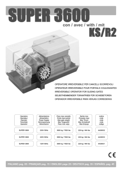
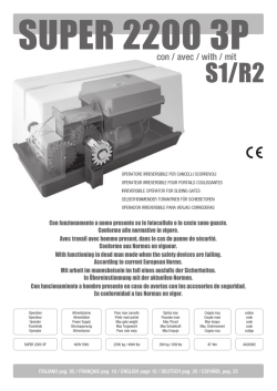

© Copyright 2026