
Mod. ISTRUZIONI PER L`USO E L`INSTALLAZIONE
Pag. 1 di 44
ISTRUZIONI PER L'USO E L’INSTALLAZIONE
INSTRUCTIONS POUR L'UTILISATION ET L’INSTALLATION
OPERATING AND INSTALLATION INSTRUCTIONS
GEBRAUCHSANWEISUNGEN UND INSTALLATION
INSTRUCIONES PARA EL USO Y LA INSTALACIÓN
Operatore irreversibile per cancelli scorrevoli - Operateur irreversible pour portails coulissantes
Irreversible operator for sliding gates - Selbsthemmender Torantrieb für Schiebetüren
Operador irreversible para verjas correderas
Mod.
K5 cK
Misure in mm
Mesures en mm
Measurements in mm
Abmessungen in mm
Medidas en mm/pulgadas
Operatore
Alimentazione
Peso max cancello
Spinta max
Operateur
Alimentation
Poids maxi du portail
Poussée maxi
Operator
Power Supply
Max gate weight
Max Thrust
Torantrieb
Stromspannung
Max Torgewicht
Max Schubkraft
Operador
Alimentación
Peso máx. verja
Empuje K
K5 CK
230V 50/60Hz
500Kg / 1100lbs
36Kg / 81lbs
K5 CK
120V 60Hz
500Kg / 1100lbs
36Kg / 81lbs
KIT K5 SC
230V 50/60Hz
500Kg / 1100lbs
36Kg / 81lbs
SC => senza cremagliera - sans cremaillere - without rack - ohne zahnstange - sin cremallera
codice
code
code
code
código
AA33685
AA33686
AD00654
I
F
GB
D
ES
I
Pag. 2 di 44
INDICE
F
GB
D
ES
Caratteristiche Tecniche ..........................................................................................pag.6
Controllo pre-installazione .......................................................................................pag.6
Sblocco d’emergenza, Fissaggio motore e cremagliera..........................................pag.7
Regolazione finecorsa, Manutenzione ....................................................................pag.7
Collegamenti elettrici ...........................................................................................pag.8-9
Controllo senso di rotazione del motore, Programmazione Tempi ......................pag.10
Programmazione codici radio ..............................................................................pag.10
Funzionamento Accessori di Comando .................................................................pag.10
Funzionamento accessori di Sicurezza .................................................................pag.11
Accessori ..............................................................................................................pag.12
Dichiarazione di Conformità...................................................................................pag.42
Esploso ..................................................................................................................pag.44
INDEX
Technical Features ................................................................................................pag.20
Checking before the Installation ............................................................................pag.20
Emergency release system, Motor and rack fitting................................................pag.21
Limit switch adjustment, Maintenance ..................................................................pag.21
Electric connections .........................................................................................pag.22-23
Checking the rotation direction of the motor, Timing ............................................pag.24
Radio code learning procedure .............................................................................pag.24
Operation of Operating Accessories......................................................................pag.24
Operation of Safety Accessories ...........................................................................pag.25
Accessories ..........................................................................................................pag.26
Declaration of Compliance.....................................................................................pag.42
Exploded view........................................................................................................pag.44
ÍNDICE
Control de pre-instalación......................................................................................pág.34
Características Técnicas .......................................................................................pág.34
Desbloqueo de emergencia, Fijación del motor y de la cremallera .......................pág.35
Fijación del final de carrera, Mantenimiento ....................................................... pág.35
Conexiones eléctricas .....................................................................................pág.36-37
Control del sentido de rotación del motor, Programación de Tiempos..................pág.38
Programación de códigos radio ............................................................................pág.38
Funcionamiento Accesorios de mando................................................................. pág.38
Funcionamiento Accesorios de Seguridad ........................................................... pág.39
Accesorios .............................................................................................................pág.40
Declaración de Coformidad ...................................................................................pág.42
Despiezo................................................................................................................pág.44
INDEX
Caractéristiques techniques ..................................................................................pag.13
Contrôle pré-installation.........................................................................................pag.13
Déblocage d'urgence, Installation moteur et crémaillère.......................................pag.14
Réglage du fin de course, Entretien ......................................................................pag.14
Branchements électriques ................................................................................pag.15-16
Contrôle du sens de rotation du moteur, Programmation des temps ....................pag.17
Procedure d’apprentissage code radio ..................................................................pag.17
Fonctionnement des Accessoires de Commande .................................................pag.17
Fonctionnements des Accessoires de Sécurité.....................................................pag.18
Accessoires ..........................................................................................................pag.19
Déclaration de conformité......................................................................................pag.42
Vue éclatée............................................................................................................pag.44
INHALT
Technische Eigenschaften.....................................................................................pag.27
Vor der Montage auszuführende Überprüfungen .................................................pag.27
Notentriegelung, Installation des antriebs und der zahnstange.............................pag.28
Einstellung des endchalters, Wartung ...................................................................pag.28
Elektroanschlüsse ............................................................................................pag.29-30
Kontrolle Motor-Drehrichtung, Programmierung Zeiten.........................................pag.31
Prozedur zur aufnahme des radio code.................................................................pag.31
Funktionsweise des Steuerzubehörs.....................................................................pag.31
Funktionsweise des Sicherheitszubehörs..............................................................pag.32
Zubehör .................................................................................................................pag.33
Konformitätserklärungen........................................................................................pag.42
Explosionszeichnungen .........................................................................................pag.44
Pag. 3 di 44
I
IMPORTANTI ISTRUZIONI PER LA SICUREZZA
INSTRUCTIONS IMPORTANTES POUR LA SECURITE
F
- ATTENZIONE É IMPORTANTE PER LA SICUREZZA DELLE PERSONE CHE VENGANO SEGUITE
TUTTE LE ISTRUZIONI
- ATTENTION IL EST IMPORTANT POUR LA SECURITE DES PERSONNES DE SUIVRE
ATTENTIVEMENT TOUTES INSTRUCTIONS
GB
1° - Questo libretto d'istruzioni è rivolto esclusivamente a del personale
specializzato che sia a conoscenza dei criteri costruttivi e dei dispositivi di
protezione contro gli infortuni per i cancelli, le porte e i portoni motorizzati (attenersi
alle norme e alle leggi vigenti).
2° - L’installatore dovrà rilasciare all’utente finale un libretto di istruzioni in accordo alla
EN 12635.
3° - L’installatore prima di procedere con l’installazione deve prevedere l’analisi dei rischi
della chiusura automatizzata finale e la messa in sicurezza dei punti pericolosi
identificati (seguendo la norma EN 12453/EN 12445).
4° - Il cablaggio dei vari componenti elettrici esterni all’operatore (ad esempio fotocellule,
lampeggianti, ecc.) deve essere effettuato secondo la EN 60204-1 e le modifiche a
questa apportate dal punto 5.2.2 della EN 12453.
5° - L’eventuale montaggio di una pulsantiera per il comando manuale del movimento
deve essere fatto posizionando la pulsantiera in modo che chi la aziona non si trovi
in posizione pericolosa; inoltre si dovrà fare in modo che sia ridotto il rischio di
azionamento accidentale dei pulsanti.
6° - Tenete i comandi dell'automatismo (pulsantiera, telecomando etc.) fuori dalla portata
dei bambini. I comandi devono essere posti ad un’altezza minima di 1,5mt dal suolo
e fuori dal raggio d’azione delle parti mobili.
7° - Prima di eseguire qualsiasi operazione di installazione, regolazione, manutenzione
dell’impianto, togliere la tensione agendo sull’apposito interruttore magnetotermico
collegato a monte dello stesso.
1° - Ce manuel d'instruction est adressé seulement au personnel specialisé qui a
une connaissance des critères de construction et des dispositifs de protection contre
les accidents en ce qui concerne les portails, les portes et les portes cochères
motorisées (suivre les normes et les lois en vigueur).
2° - L’installateur devra remettre, à l’utilisateur final, une notice technique conformément
à la norme EN12635.
3° - L’installateur doit avant de procéder à l’installation, prévoir l’analyse des risque de
l’automatisation finale et la mise en sécurité des zones dangereuses identifiées
(selon la norme EN 12453/12445).
4° - Le câblage des différents éléments électriques externes à l’opérateur (ex.
photocellules, clignotants, etc…) doit être effectué selon la norme EN 60204-1 et
aux modifications apportées au paragraphe 5.2.2 de la norme EN 12453
5° - La pose éventuelle d’une commande manuelle par bouton pour la mise en marche
de l’automatisme ne doit pas être positionnée dans une zone qui mettrait en danger
l’opérateur ; il est également important de l’installer de sorte à éviter toute action
accidentelle des boutons.
6° - Gardez les commandes de l'automatisme (boutons poussoirs, télécommande etc.)
hors de la portée des enfants. Les commandes doivent être placées au minimum à
1,5 m du sol, et hors de rayon d’action des pièces mobiles.
7° - Avant d’exécuter quelconques opérationd’installation, réglage, entrietien de
l’installation, couper la tension avec l’interrupteur magnétothermique approprié
connecté en amont.
- ATTENZIONE UNA SCORRETTA INSTALLAZIONE PUÓ PORTARE A DANNI RILEVANTI
LA DITTA RIB NON ACCETTA NESSUNA RESPONSABILITÀ per eventuali danni
provocati dalla mancata osservanza nell'installazione delle norme di sicurezza, delle
leggi attualmente in vigore e delle istruzioni stesse.
- ATTENTION UNE INSTALLATION INCORRECTE PEUT CAUSER DE GRANDS DOMMAGES
L'ENTREPRISE R.I.B. N'ACCEPTE AUCUNE RESPONSABILITÉ pour des dommages
éventuels provoqués par le manque d'observation lors de l'installation des normes de
sécurité de lois actuellement en vigueur et des instructions même.
CONSERVARE CON CURA QUESTE ISTRUZIONI
GARDER MODE D’EMPLOI
IMPORTANTI ISTRUZIONI DI SICUREZZA PER
L’INSTALLAZIONE
INSTRUCTIONS TRÈS IMPORTANTES EN MATIÈRE DE
SÉCURITÉ POUR L'INSTALLATION
1° - Se non é previsto nella centralina elettrica, installare a monte della medesima
un'interruttore di tipo magnetotermico (onnipolare con apertura minima dei contatti
pari a 3mm) che riporti un marchio di conformità alle normative internazionali. Tale
dispositivo deve essere protetto contro la richiusura accidentale (ad esempio
installandolo dentro quadro chiuso a chiave).
2° - Per la sezione ed il tipo dei cavi la RIB consiglia di utilizzare un cavo di tipo H05RNF con sezione minima di 1,5mm2 e comunque di attenersi alla norma IEC 364 e alle
norme di installazione vigenti nel proprio Paese.
3° - Posizionamento di un’eventuale coppia di fotocellule: Il raggio delle fotocellule deve
essere ad un’altezza non superiore a 70 cm dal suolo e ad una distanza dal piano di
movimento dell’anta non superiore a 20 cm. Il loro corretto funzionamento deve
essere verificato a fine installazione in accordo al punto 7.2.1 della EN 12445.
4° - Per il soddisfacimento dei limiti imposti dalla EN 12453, se la forza di picco supera il
limite normativo di 400 N è necessario ricorrere alla rilevazione di presenza attiva
sull’intera altezza del cancello (fino a 2,5m max) - Le fotocellule in questo caso sono
da applicare all’esterno tra le colonne ed all’interno per tutta la corsa della parte
mobile ogni 60÷70cm per tutta l’altezza delle colonne del cancello fino ad un
massimo di 2,5m (EN 12445 punto 7.3.2.1) - es. colonne alte 2,2mt => 6 coppie di
fotocellule - 3 interne e 3 esterne (meglio se dotate di sincronismo - 6 FIT SYNCRO
con 2 TX SYNCRO).
1° - Si la centrale électrique ne dispose d'aucun interrupteur, il faut en installer un de
type magnétothermique en amont de cette dernière (omnipolaire avec ouverture
minimale des contacts correspondant à 3mm); la marque de cet interrupteur devra
être en conformité avec les normes internationales. Ce dispositif doit être protégé
contre toute remise en fonction accidentelle (ex. en l’installant dans un coffre
fermant à clé).
2° - En ce qui concerne la section et le type des câbles, le conseil de la RIB est celui
d'utiliser un câble de type H05RN-F présentant une section minimale de 1,5mm2 et,
quoi qu'il en soit, de se conformer à la norme IEC 364, ainsi qu'aux normes
d'installation en vigueur dans le pays de destination.
3° - Positionnement d’un éventuel jeu de photocellules : le faisceau des photocellules ne
doit pas être à une hauteur supérieure à 70 cm du sol et 20 cm du bord du vantail.
Leur correct effectivité fonctionnement doit être vérifié terminant l’installation, selon
le point de la 7.2.1 de la EN 12445.
4° - Afin de satisfaire aux limites imposées par la norme EN 12453, si la force d’impact
dépasse la limite de 400N, il sera nécessaire de détecter une présence sur la
hauteur totale du portail (jusqu'à un maximum de 2,5m) - Les cellules photoélectriques dans ce cas-ci doivent être s'appliquent extérieurement entre les colums
et intérieurement pour toute la course de la pièce de mobil chaque 60÷70cm pour
toute la taille de la colonne de la porte jusqu'à un maximum de 2,5m (EN 12445
point 7.3.2.1) - exemple: taille 2,2m de colonne = > 6 copies des cellules photoélectriques - 3 internes et 3 externes (meilleur si complet du dispositif de syncronism
- FIT SYNCRO avec TX SYNCRO).
N.B.:É obbligatoria la messa a terra dell'impianto
I dati descritti nel presente manuale sono puramente indicativi.
La RIB si riserva di modificarli in qualsiasi momento.
Realizzare l’impianto in ottemperanza alle norme ed alle leggi vigenti.
N.B.:La mise à terre de l'installation est obligatoire.
Les données figurant dans le présent manuel sont fournies à titre purement indicatif.
La RIB se réserve le droit de les modifier à tout moment, sans aucun préavis.
Effectuer l'installation en conformité avec les normes et les lois en vigueur.
D
ES
I
Pag. 4 di 44
F
IMPORTANT SAFETY INSTRUCTIONS
WICHTIGE ANWEISUNGEN FÜR DIE SICHERHEIT
GB
- WARNING IT IS IMPORTANT FOR THE SAFETY OF PERSONS TO FOLLOW ALL
INSTRUCTIONS
- ACHTUNG UM DIE SICHERHEIT VON PERSONEN VOLLKOMMEN
GARANTIEREN ZU KöNNEN, IST ES WICHTIG, DASS ALLE
1° - This instruction booklet is exclusively dedicated to specialized staff who are
aware of the construction criteria and of the accident prevention protection devices
for motorized gates and doors (according to the current regulations and laws).
2° - In the compliance with the EN 12635, the fitter must issue an istruction manual.
3° - Even before beginning with the installation, fitters must examine the risks of an
automatic closing and find an appropriate solution for these cases (in accordance
with the EN 12453 and EN 12445).
4° - All external electrical wirings to the operators (e.g. photocells, blinkers etc.) must be
carried out in compliance with the EN 60204-1 norm and their subsequent
modifications brought to them with the point 5.2.2 of the EN 12453.
5° - When a command pushbutton is also installed, it is necessary that the istallation is
carried out in such a way that the operator is in a safe position, and so to reduce to a
minimum the risks of accidental operation.
6° - Keep the automatic control (push-button, remote control, etc) out of the reach of
children. The control systems must be installed at a minimum height of 1.5m from
the ground surface and not interfere with the mobile parts.
7° - Before starting any installation and operation or maintenance work make sure to cut
off power supply by turning the general magnetothermic switch off.
1° - Diese Montageanweisung ist ausschließlich für geschultes Fachpersonal
bestimmt, das mit den Montagevorschriften und den Schutzvorrichtungen zur
Verhinderung von Unfällen bei motorisierten Toren vertraut ist (nach den aktuellen
Normen und Gesetzen).
2° - In Uebereistimmung mit der EN12635, aus dem selbigen Handbuch.
3° - Bevor sie mit der installation beginnen,muessen sie eine geeignete Schutzfunktion
fuer das automatische Schliessen finden(immer in Anlehnung an die EN 12453 und
EN12445).
4°- Alle externen elektrischen Kabel (z.B.zur Fotozelle,Blinker usw.)muessen in Einklang
mit der EN60204-1 gebracht werden, und Veraenderungen nach Punkt 5.2.2 der
EN12453 vorgenommen werden.
5°- Wenn sie ein Drucktaster installieren ist es wichtig,das er so installiert wird, das er
nicht ausversehen durch eine Person betaetigt werden kann, nur wenn es gewollt ist.
6° - Bewahren Sie die Geräte für die automatische Bedienung (Drucktaster, Funksender,
u.s.w.) an einem für Kinder unzugänglichen Platz auf. Die Steuerungen müssen auf
einer Mindesthöhe von 1,5 m angebracht werden und sich ausserhalb der Raumes
der bewegenden Teile befinden.
7° - Bevor Sie eine Installation oder Wartungsarbeit an der Anlage durchführen, müssen
Sie kontrollieren, dass die Anlage spannungsfrei geschaltet ist. e le istruzioni stesse.
D
ES
- WARNING - INCORRECT INSTALLATION CAN LEAD TO SEVERE INJURY
R.I.B. IS NOT LIABLE for any damage caused by not following the safety regulations, the
instructions and laws at present in force not being observed during installation.
SAVE THESE INSTRUCTIONS
- ACHTUNG EINE FALSCHE INSTALLATION KANN ZU BEDEUTENDEN SHÄDEN FÜHREN
R.I.B. HAFTET NICHT für eventuelle Schäden, die bei der Installation durch
Nichtbeachtung der jeweils gültigen Sicherheitsvorschriften und Anweisungen entstehen.
INSTALLATIONSVORSCHRIFTEN BEACHTET WERDEN
IMPORTANT SAFETY INSTRUCTIONS FOR THE INSTALLATION
1° - Install a thermal magnetic switch (omnipolar, with a minimum contact opening of 3
mm) before the control board, in case this is not provided with it. The switch shall be
guaranteed by a mark of compliance with international standards. Such a device
must be protected against accidental closing (e.g. Installing it inside the control panel
key locked container).
2° - As far as the cable section and the cable kind are concerned, RIB suggests to use
an H05RN-F cable, with a minimum section of 1,5mm2, and to follow, In any case,
the IEC 364 standard and Installation regulations In force In your Country.
3° - Positioning of an eventual pair of photocells: The beam of the photocells must be at
an height not above the 70 cm from the ground, and, should not be more than 20 cm
away from the axis of operation of the gate (Sliding track for sliding gate or door, and
the hinges for the swing gate). In accordance with the point 7.2.1 of EN 12445 their
correct functioning must be checked once the whole installation has been
completed.
4° - In order to comply with the limits defined by the EN 12453 norm, if the peak force is
higher than the limit of 400N set by the norm, it is necessary to use an active
obstacle detection system on the whole height of the gate (up to a maximum of
2,5m) - The photocells in this case must be apply externally between the colums and
internally for all the race of the mobil part every 60÷70cm for all the height of the
column of the gate up to a maximum of 2,5m (EN 12445 point 7.3.2.1). example:
column height 2,2m => 6 copies of photocells - 3 internal and 3 external (better if
complete of syncronism feature - FIT SYNCRO with TX SYNCRO).
N.B.: THE SYSTEM MUST BE GROUNDED
Data described by this manual are only Indicative and RIB reserves to modify them at
any time. Install the system complying with current standards and regulations.
WICHTIGE SICHERHEITSVORSCHRIFTEN FÜR DIE
INSTALLATION
1° - Wenn nicht bereits an der elektrischen Schaltzentrale vorgesehen, muss vor der
Schaltzentrale ein thermomagnetischer Schalter installiert werden (omnipolar, mit
einer minimalen Kontaktöffnung von 3 mm), der ein von den internationalen Normen
anerkanntes Konformitätszeichen besitzt. Solch ein Geraet muss vor Vandalismus
geschuetzt werden(z.B.mit einen Schluesselkatsten in einem Panzergehaeuse)
2° - RIB empfiehlt den Kabeltyp H05RN-F mit einem minimalen Querschnitt von 1,5mm2
generell sollten die Normative IEC 364 und alle anderen geltenden Montagenormen
des Bestimmungslandes eingehalten werden.
3°- Position des ersten paar Fotozellen: Der sollten nicht hoeher als 70cm vom Boden
sein, und sollte nicht mehr als 20 cm entfernt von der Achse des Tores sitzen (das
gilt fuer Schiebe und Drehtore). In Übereinstimmung mit dem Punkt 7.2.1 der EN
12445 Norm, ihr korrektes Funktionieren muß einmal überprüft werden.
4°- In Einklang mit der Norm EN12453, ist es bei Toren notwendig eine komplette
Sicherheitslieiste zu installieren, bei denen mehr als 400N Kraft aufgewand werden
muessen, um das Tor zum anhalten zu bringen (Maximum von 2,5m anwenden) Die Fotozellen müssen in diesem Fall sein beantragen außen zwischen den colums
und innerlich das ganzes Rennen des mobil Teils jede 60÷70cm für die ganze Höhe
der Spalte des Gatters bis zu einem Maximum von 2,5m - EN 12445 Punkt 7.3.2.1).
Beispiel: Spalte Höhe 2,2m => 6 Kopien von Fotozellen - 3 intern und 3 extern
(besser, wenn komplett von der syncronism Eigenschaft - FIT SYNCRO mit TX
SYNCRO).
ANMERKUNG: Die Erdung der Anlage ist obligatorisch
Die in diesem Handbuch aufgeführten Daten sind ausschließlich empfohlene Werte.
RIB behält sich das Recht vor, das Produkt zu jedem Zeitpunkt zu modifizieren.
Die Anlage muss in Übereinstimmung mit den gültigen Normen und Gesetzen montiert
werden.
Pag. 5 di 44
I
IMPORTANTES INSTRUCCIONES PARA LA SECURIDAD
F
- ATENCIÓN PARA LA SEGURIDAD DE LAS PERSONAS ES IMPORTANTE QUE SE OBSERVEN
TODAS LAS INSTRUCCIONES.
GB
1° - Este manual de instrucciones está exclusivamente dirigido a personal especializado
que conozca los criterios de construcción y de los dispositivos de protección contra
accidentes con cancelas, puertas y portales motorizados (atenerse a las normas y a
las leyes vigentes).
2° - El instalador tendrá que dar al utilizador final un manual de instrucciones de
acuerdo con la EN 12635.
3° - El instalador antes de proceder con la instalación tiene que hacer un analisis de los
riesgos del cierre automatizado final y la puesta en seguridad de los puntos
identificados como peligrosos (siguiendo las normas EN 12453 / EN 12445).
4° - El cablaje de los varios componentes eléctricos externos al operador (por ejemplo
fotocélulas, los intermitentes, etc) tiene que ser efectuado según la EN 60204-1 y a
las modificas sucesivas aportadas por el punto 5.2.2 della EN 12453.
5° - El eventual montaje de un panel de mandos para la gestión del movimiento manual
tiene que ser efectuado posicionando el panel en modo que quien lo accione no se
encuentre en una posición peligrosa; además se tiene que hacer en modo que el
riesgo de accionamiento accidental de los pulsadores sea mínimo.
6° -Tener los mandos del automatismo (panel de mandos, mando a distancia, etc.) lejos
del alcance de los niños. Los mandos tienen que ser puestos a una altura mínima de
1,5mt del suelo y fuera del radio de acción de las partes móviles.
7° - Antes de ejecutar cualquier operación de instalación, ajuste el mantenimiento del
sistema, quitar la corriente accionando el respectivo interruptor magnetotérmico
conectado antes del mismo.
- CUIDADO UNA INCORRECTA INSTALACIÓN PUEDE CAUSAR GRAVES DAÑOS
LA EMPRESA RIB NO ES RESPONSABLE por eventuales daños provocados por la
falta de respeto de las normas de seguridad, durante la instalación y de las leyes
actualmente vigentes.
CONSERVAR CUIDADOSAMENTE ESTAS INSTRUCCIONES.
IMPORTANTES INSTRUCCIONES DE SEGURIDAD
PARA LA INSTALACIÓN
1° - En el caso de que no sea previsto en la central eléctrica, instalar antes de la misma,
un interruptor de tipo magnetotérmico (omnipolar con una abertura mínima de los
contactos de 3mm) que dé un sello de conformidad con las normas internacionales.
Este dispositivo tiene que estar protegido contra cierres accidentales (por ejemplo
instalándolo dentro de un panel cerrado a llave).
2° - Para la sección y el tipo de los cables, la RIB aconseja utilizar cables de tipo
H05RN-F con sección mínima de 1,5mm2 e igualmente atenerse a la norma IEC 364
y a las normas de instalación del propio País.
3° - Posicionamiento eventual de un par de fotocélulas. El rayo de las fotocélulas no
debe estar a más de 70 cm de altura desde el suelo y a una distancia de la
superficie de movimiento de la puerta, no superior a 20 cm. El correcto
funcionamiento tiene que ser controlado al final de la instalación de acuerdo con el
punto 7.2.1 de la EN 12445.
4° - Para satisfascer los límites impuestos por la EN 12453, si la fuerza de punta supera
el límite normativo de 400 N, es necesario recurrir al control de presencia activa en
toda la altura de la puerta (hasta a 2,5m max). Las fotocélulas en este caso se
tienen que colocar en el exterior entre las columnas y en el interior por todo el
recorrido de la parte móvil cada 60÷70cm en toda la altura de las columnas de la
cancela hasta un máximo de 2,5m (EN 12445 punto 7.3.2.1) - es. columnas altas de
2,2mt => 6 par de fotocélulas - 3 internas y 3 externas (mejor si están provistas de
sincronismo - 6 FIT SYNCRO con 2 TX SYNCRO).
PS.: Es obligatorio la puesta a tierra del sistema.
Los datos descritos en el presente manual son sólamente indicativos.
La RIB se reserva de modificarlos en cualquier momento.
Realizar el sistema respetando las normas y las leyes vigentes.
D
ES
I
T
A
L
I
A
N
O
Pag. 6 di 44
LAY-OUT IMPIANTO
ABCDEFGLM-
Operatore K5
Fotocellule esterne
Cremagliera
Selettore a chiave
Antenna radio
Lampeggiatore
Limitatori di corsa
Costa meccanica
Costa pneumatica
CARATTERISTICHE TECNICHE
CONTROLLO PRE-INSTALLAZIONE
Operatore irreversibile per cancelli scorrevoli aventi un peso massimo di 500 Kg.
L'irreversibilità di questo operatore fa si che il cancello non richieda alcun tipo di
serratura elettrica per un'efficace chiusura.
Il motore è protetto da una sonda termica che in caso di utilizzo prolungato
dell'apparecchiatura, interrompe momentaneamente il movimento.
!! IL CANCELLO DEVE MUOVERSI SENZA ATTRITI !!
N.B. È obbligatorio uniformare le caratteristiche del cancello alle norme e leggi vigenti.
La porta può essere automatizzata solo se in buono stato e se rispondente alla norma
EN 12604.
- L’anta non deve presentare porte pedonali. In caso contrario occorrerà prendere
opportune precauzioni in accordo al punto 5.4.1 della EN12453 (ad esempio impedire il
movimento del motore quando il portoncino è aperto, grazie ad un microinterruttore
opportunamente collegato in centralina).
- Non bisogna generare punti di intrappolamento (ad esempio tra anta aperta del
cancello e cancellata).
- Oltre ai finecorsa presenti nell’unità, è necessario che a ciascuna delle due posizioni
estreme della corsa sia presente un fermo meccanico fisso che arresti il cancello nel
caso di malfunzionamento dei finecorsa. A tal fine il fermo meccanico deve essere
dimensionato per sopportare la spinta statica del motore più l’energia cinetica del
cancello (12) (Fig. 2).
- Le colonne del cancello devono avere superiormente delle guide antideragliamento
(Fig. 3) per evitare involontari sganciamenti.
N.B.: Eliminare fermi meccanici del tipo descritto in figura 3.
Non devono essere presenti fermi meccanici al di sopra del cancello perché non sono
sufficientemente sicuri.
Fig. 2
CARATTERISTICHE
TECNICHE
K5
Peso max cancello
Kg
Velocità di traino
m/sec
Forza max di spinta
N
Cremagliera modulo
Componenti da installare secondo la norma EN12453
TIPO DI COMANDO
a uomo presente
a impulsi in vista (es. sensore)
a impulsi non in vista (es. telecomando)
automatico
USO DELLA CHIUSURA
Persone esperte
Persone esperte
(fuori da area pubblica*) (area pubblica)
A
B
CoE
CoE
CoE
C e D, o E
C e D, o E
C e D, o E
0,160
360
4
Alimentazione e frequenza CEE
Fig. 3
500
230V~ 50/60Hz
Potenza motore
W
206
Assorbimento
A
0,93
Condensatore
µF
8
n° cicli normativi
n°
10 - 30s/2s
n° di cicli consigliati al giorno
300
Uso illimitato
Servizio
60%
non possibile
C e D, o E
C e D, o E
C e D, o E
n° cicli garantiti
18/5m
* esempio tipico sono le chiusure che non accedono a pubblica via
A: Pulsante di comando a uomo presente (cioè ad azione mantenuta), come cod. ACG2013
B: Selettore a chiave a uomo presente, come cod. ACG1010
C: Regolazione della forza del motore
D: Costole come cod. ACG3010 e/o altri dispositivi di limitazione delle forze entro i limiti della norma
EN12453 - Appendice A.
E: Fotocellule, es. cod.ACG8026 (Da applicare ogni 60÷70cm per tutta l’altezza della colonna del
cancello fino ad un massimo di 2,5m - EN 12445 punto 7.3.2.1)
Lubrificazione a grasso
Bechem - RHUS 550
Peso max
Kg
8
Rumorosità
db
<70
Temperatura di lavoro
°C -10 ÷ +55°C
Grado di protezione
IP
54
Pag. 7 di 44
SBLOCCO D'EMERGENZA
Da effettuare dopo aver tolto l'alimentazione elettrica al motore.
Per poter agire manualmente sul cancello è sufficiente ruotare la chiave RIB in senso
orario. Per ripristinare il funzionamento elettrico operare in senso contrario (Fig. 4).
Per poter eseguire in modo sicuro la movimentazione manuale dell’anta occorre
verificare che:
- sull’anta siano presenti maniglie idonee;
- tali maniglie siano posizionate in modo da non creare punti di pericolo durante il loro
utilizzo;
- lo sforzo manuale per muovere l’anta non superi i 225N per i cancelli posti su siti
privati ed i 390N per i cancelli posti su siti commerciali ed industriali (valori indicati nel
punto 5.3.5 della norma EN 12453).
Fig. 4
FISSAGGIO MOTORE E CREMAGLIERA
Misure in mm
La base dell'operatore K5 è dotata di 2 zanche così da poterlo cementare al suolo.
La cremagliera va fissata a una certa altezza rispetto alla piastra di fissaggio del motore.
Questa altezza può essere variata grazie a delle asole presenti sulla cremagliera.
Le cremagliere non devono essere saldate, ma solo fissate con delle viti filettate al
cancello. La registrazione in altezza viene fatta affinché il cancello durante il movimento,
non si appoggi sull'ingranaggio di trazione del riduttore (Fig. 5,6).
Per fissare la cremagliera sul cancello eseguire dei fori di Ø 5 mm e filettarle utilizzando
un maschio del tipo M6.
L'ingranaggio di traino deve avere circa da 0,5 a 1 mm di agio rispetto alla cremagliera.
Fig. 5
FISSAGGIO FINECORSA
L'arresto del cancello avviene attraverso due camme montate alle estremità della
cremagliera (Fig. 7).
La regolazione della corsa di apertura e chiusura, si ottiene spostando le medesime sui
denti della cremagliera.
Per fissare la camme, avvitare a fondo le viti (1).
N.B: Oltre alle camme di fermo elettrico sopraesposte è obbligatoria l'installazione di
fermi meccanici robusti che non permettano la fuoriuscita del cancello dalle guide
superiori.
Fig. 6
MANUTENZIONE
1
Fig. 7
Da effettuare solamente da parte di personale specializzato dopo aver tolto
l'alimentazione elettrica al motore.
Pulire periodicamente, a cancello fermo, la guida di scorrimento da sassi e altra
sporcizia.
I
T
A
L
I
A
N
O
I
T
A
L
I
A
N
O
Pag. 8 di 44
COLLEGAMENTI ELETTRICI
SPARK
COLLEGAMENTO
MOTORE
TX1
RX1
RX2
TX2
FIT SYNCRO
BLOCK
o
pulsantiera
FLAT
COSTA
Pag. 9 di 44
Cod. BC07056 K-CRX 230-50/60Hz
Cod. BC07057 K-CRX 120-60Hz
B - SETTAGGI
A - CONNESSIONI
J1=>
NON TOCCARE IL PONTICELLO !
SE VIENE RIMOSSO L’OPERATORE NON FUNZIONA!
J2=> AERIAL
LSC
LSO
COM
Antenna radio
Contatto finecorsa che ferma la chiusura
Contatto finecorsa che ferma l’apertura
Comune dei contatti
J3 => L-N
Alimentazione 230Vac 50/60Hz (120V/60Hz a richiesta)
J4 => TERRA
Collegamento dei conduttori di terra (Obbligatorio)
J5 => RADIO
Connettore per radio ricevitore esterno 12Vdc (modelli non CRX)
Modulo radio incorporato (modelli CRX)
J6 => D-D+
COM
K BUTT.
PHOT.
EDGE
Alimentazione accessori a 12Vdc
Comune dei contatti
Contatto impulso singolo (NA)
Contatto fotocellule (NC)
Contatto coste in apertura e chiusura (NC)
Buzzer - Collegamento segnalatore sonoro (12Vdc max 200 mA)
MICROINTERRUTTORI PER PROCEDURE
DIP 1
CONTROLLO SENSO DI ROTAZIONE DEL MOTORE (ON)
(PUNTO C).
DIP 2 PROGRAMMAZIONE TEMPI (ON) (PUNTO D).
DIP 1-2 MEMORIZZAZIONE/CANCELLAZIONE CODICI RADIO (DIP 1 ON seguito da
DIP 2 ON) (PUNTO E) SOLO PER MODELLI CRX.
MICROINTERRUTTORI DI GESTIONE
DIP 3
DIP 4
DIP 5
DIP 6
DIP 7
DIP 8
Tempo di attesa prima della chiusura automatica (ON)
Fotocellule sempre attive (OFF) - Fotocellule attive solo in chiusura (ON)
Prelampeggio (ON) - Lampeggio normale (OFF)
Comando impulso singolo (K BUTT e RADIO) passo passo (ON) - automatico
(OFF)
Freno elettronico (ON-attivato)
Rallentamento (OFF)
S1 => PROG. Pulsante per la programmazione
JP1 => Jumper di reset (in caso di necessità, ponticellate il jumper di RESET almeno
per 1 secondo (operazione eseguibile anche con un cacciavite).
JP2 => A disposizione per implementazioni future
JP3 => Se chiuso la funzione black out non é attiva
Se aperto la funzione black out é attiva (vedi TAB1 pag.10)
TORQUE - REGOLATORE ELETTRONICO DELLA FORZA
J7 =>
Lampeggiatore (max 40W )
U - MOTOR
Collegamento comune motore
V-W - MOTOR Collegamento invertitori e condensatore motore
J8 => PROBE
connettore per collegamento sonda riscaldatore (opzionale)
R1 => TRIMMER LOW SPEED
regolazione della velocità di rallentamento in
apertura e chiusura
R2 => TRIMMER TORQUE
regolazione della frizione elettronica
RELE’ E COMANDO MOTORE
K1 =>
K2 =>
K3 =>
Q1 =>
Comando lampeggiatore
Comando direzione chiusura
Comando direzione apertura
TRIAC - Comando motore in apertura e chiusura
La regolazione della forza viene fatta ruotando il Trimmer TORQUE che serve a variare la
tensione di uscita ai capi del motore (ruotando in senso orario si da più forza al motore).
Tale forza si include automaticamente dopo 3 secondi dall’inizio di ogni manovra.
Questo per dare il massimo di spunto al motore al momento della partenza.
NOTA: SE QUESTO TRIMMER VIENE REGOLATO DOPO AVERE ESEGUITO LA
PROCEDURA DI PROGRAMMAZIONE, E’ POSSIBILE CHE LA MISURA DI
INIZIO RALLENTAMENTO SUBISCA DELLE VARIAZIONI (IN PIU’ O IN MENO
RISPETTO ALLA PRECEDENTE), PERTANTO SE SI ESEGUE UNA NUOVA
REGOLAZIONE DEL TRIMMER, SI CONSIGLIA DI RIESEGUIRE LA
PROGRAMMAZIONE DEI TEMPI.
LOW SPEED
REGOLATORE DELLA VELOCITA’ DI RALLENTAMENTO
Se dip 8 su OFF, la regolazione del rallentamento viene fatta ruotando il Trimmer LOW
SPEED che serve a variare la velocita del motore in fase di accostamento di fine apertura
e chiusura (ruotandolo in senso orario si da più velocità al motore).
Il rallentamento viene determinato automaticamente dalla centralina in fase di
programmazione tempi, e viene attivato a circa 15÷20 cm prima del raggiungimento del
finecorsa di apertura o di chiusura.
I
T
A
L
I
A
N
O
I
T
A
L
I
A
N
O
Pag. 10 di 44
PARTENZA GRADUALE
Ogni volta che viene comandato il cancello viene eseguita di default una partenza
graduale pari a 1 secondo.
FRENO ELETTRONICO
Se non usato il rallentamento (dip 8 ON), consigliamo di abilitare il dip 7 a ON usufruendo
di un freno elettronico che limita l’inerzia del cancello quando raggiunge i finecorsa
elettrici.
SEGNALAZIONI LED
DL1 - (Rosso)
DL2 - (Verde)
DL3 - (Rosso)
DL4 - (Rosso)
DL5 - (Rosso)
DL6 - (Verde)
DL7 - (Rosso)
DL8 - (Rosso)
- Programmazione attivata
- Programmazione radio attivata (solo nei modelli CRX)
- Contatto finecorsa di apertura (NC)
- Contatto finecorsa di chiusura (NC)
- Cancello in chiusura
- Cancello in apertura
- Contatto fotocellule (NC)
- Contatto coste (NC)
C - CONTROLLO SENSO DI ROTAZIONE DEL MOTORE
Questo controllo ha il compito di agevolare l’installatore durante la messa in opera
dell’impianto, o per eventuali controlli successivi.
1 - Dopo aver regolato i finecorsa elettrici, posizionare il cancello a metà corsa tramite lo
sblocco manuale.
2 - Mettere il DIP1 in posizione ON => il led DL1 inizia a lampeggiare.
3 - Premere e mantenere premuto il pulsante PROG (il movimento é eseguito ad uomo
presente, apre-stop-chiude-stop-apre-etc...) => il LED ROSSO DL5 “CLOSE” si
accende e il cancello deve chiudere (nel caso contrario rilasciare il pulsante PROG e
invertire i fili del motore V e W) e fermarsi in seguito al contatto con il finecorsa
elettrico (se questo non succede rilasciare il pulsante PROG ed invertire i due fili del
finecorsa LSO e LSC).
4 - Premere il pulsante PROG e mantenerlo premuto => il LED VERDE DL6 “OPEN” si
accende e il cancello deve aprire e in seguito fermarsi al contatto con il finecorsa
elettrico.
5 - Dopo 2 sec. e fino a 10 sec di lavoro consecutivi in apertura o chiusura, si
innesca automaticamente la frizione elettronica. Eseguite la regolazione della
frizione elettronica agendo sul trimmer TORQUE.
6 - Dopo 10 sec. di lavoro consecutivi in apertura o in chiusura, si innesca
automaticamente il rallentamento (se DIP 8 OFF). Eseguite la regolazione della
velocità rallentata agendo sul trimmer LOW SPEED scegliendo la velocità
desiderata.
7 - Al termine del controllo e delle regolazioni dei trimmer rimettere DIP1 in
posizione OFF. Il led DL1 si spegne segnalando l’uscita dal controllo.
N.B.: Durante questo controllo le coste e le fotocellule non sono attive.
D - PROGRAMMAZIONE TEMPI
La programmazione può essere eseguita con il cancello in qualsiasi posizione.
1 - Mettete il microinterruttore DIP 2 in posizione ON => Il led DL1 emetterà dei lampeggi
brevi.
2 - Premete il pulsante PROG. => il cancello si chiude. Dopo 2 secondi che si é chiuso, il
cancello si riapre automaticamente. A fine apertura si ferma. Attendete il tempo che
desiderate il cancello resti aperto (escludibile con DIP3 OFF).
3 - Premete il pulsante PROG. per comandare la chiusura del cancello (il led DL1 smette
di lampeggiare, nello stesso istante si ferma anche il conteggio del tempo d’attesa
prima della chiusura automatica - max 5 minuti).
4 - Raggiunto il finecorsa di chiusura il cancello si ferma.
5 - A FINE PROGRAMMAZIONE RIMETTERE IL DIP 2 SU OFF.
DURANTE LA PROGRAMMAZIONE LE SICUREZZE SONO ATTIVE ED IL LORO
INTERVENTO FERMA LA PROGRAMMAZIONE (IL LED DL1 DA LAMPEGGIANTE
RIMANE ACCESO FISSO). PER RIPETERE LA PROGRAMMAZIONE POSIZIONARE
IL DIP 2 SU OFF E RIPETERE LA PROGRAMMAZIONE SOPRA DESCRITTA.
NOTA: Il rallentamento viene determinato automaticamente dalla centralina in fase di
programmazione tempi, e viene attivato a circa 15÷20 cm prima del
raggiungimento del finecorsa di apertura o chiusura.
E – PROGRAMMAZIONE CODICI RADIO
(SOLO MODELLI CRX)
1 - La programmazione può essere eseguita con il cancello in qualsiasi posizione.
ATTENZIONE: se Dip 3 ON (tempo di attesa prima della chiusura automatica) la
programmazione non può essere effettuata a cancello totalmente
aperto.
2 - Posizionare DIP 1 - ON e successivamente il DIP 2 - ON => il led DL1 di
programmazione lampeggerà, con frequenza di 1 sec. ON e 1 sec. OFF, per 10
secondi che è il tempo utile alla programmazione del codice.
3 - Premere il tasto del telecomando (normalmente il canale A) entro i 10 secondi
impostati. Se il telecomando viene correttamente memorizzato il led DL2 (verde)
emette un lampeggio.
4 - Il tempo di programmazione dei codici si rinnova automaticamente per poter
memorizzare il telecomando successivo.
5 - Per terminare la programmazione lasciare trascorrere 10 sec., oppure premere per un
attimo il pulsante PROG. => il led DL1 di programmazione smetterà di lampeggiare.
6 - Riposizionare DIP 1 - OFF e DIP 2 - OFF.
7 - Fine procedura.
PROCEDURA CANCELLAZIONE TOTALE CODICI RADIO
La programmazione può essere eseguita con il cancello in qualsiasi posizione.
ATTENZIONE: se Dip 3 ON (tempo di attesa prima della chiusura automatica) la
programmazione non può essere effettuata a cancello totalmente
aperto.
1 - Posizionare il DIP 1 - ON e successivamente il DIP 2 - ON.
2 - Il led DL1 di programmazione lampeggerà con frequenza di 1 sec. ON e 1 sec. OFF
per 10 sec.
3 - Durante i 10 secondi => premere e mantenere premuto il pulsante PROG. per 5
secondi => la cancellazione della memoria viene segnalata da due lampeggi del led
verde DL2.
4 - In seguito il led DL1 di programmazione rimane attivo ed è possibile inserire nuovi
codici come da procedure sopra descritte.
SEGNALAZIONE MEMORIA SATURA
La programmazione può essere eseguita con il cancello in qualsiasi posizione.
ATTENZIONE: se Dip 3 ON (tempo di attesa prima della chiusura automatica) la
programmazione non può essere effettuata a cancello totalmente
aperto.
1 - Posizionando DIP 1 - ON e successivamente DIP 2 - ON.
2 - Il led verde DL2 lampeggia per 6 volte segnalando memoria piena (60 codici presenti).
3 - Successivamente il led DL1 di programmazione rimane attivo per 10 secondi,
consentendo un eventuale cancellazione totale dei codici.
FUNZIONAMENTO ACCESSORI DI COMANDO
PULSANTE DI COMANDO (COM-K BUTTON)
Se DIP6 su ON => Esegue un comando ciclico dei comandi apre-stop-chiude-stop-apreecc.
Se DIP6 su OFF => Esegue l’apertura a cancello chiuso.
Se azionato durante il movimento di apertura non ha effetto.
Se azionato a cancello aperto lo chiude e durante la chiusura se azionato lo fa riaprire.
FUNZIONE OROLOGIO (solo in modalità di funzionamento automatico DIP 6 OFF)
Questa funzione é utile nelle ore di punta, quando il traffico veicolare risulta rallentato (es.
entrata/uscita operai, emergenze in zone residenziali o parcheggi e, temporaneamente,
per traslochi).
MODALITÁ DI APPLICAZIONE
Collegando un interruttore e/o un orologio di tipo giornaliero/settimanale (al posto o in
parallelo al pulsante di comando n.a. “COM-K BUTTON”), é possibile aprire e mantenere
aperto il cancello finché l’interruttore rimane premuto o l’orologio rimane attivo.
A cancello aperto vengono inibite tutte le funzioni di comando.
Al rilascio dell’interruttore, o allo scadere dell’ora impostata, si avrà la chiusura immediata
dell’automazione.
TELECOMANDO
Se DIP6 su ON => Esegue un comando ciclico dei comandi apre-stop-chiude-stop-apre
etc.
Se DIP6 su OFF => Esegue l’apertura a cancello chiuso.
Se azionato durante il movimento di apertura non ha effetto.
Se azionato con cancello aperto, lo chiude e durante la chiusura se azionato lo fa riaprire.
CHIUSURA AUTOMATICA CON APERTURA TOTALE
I tempi di pausa prima di avere la chiusura automatica in apertura totale del cancello
vengono registrati durante le programmazioni dei tempi.
Il tempo di pausa massimo e di 5 minuti.
l tempi di pausa sono attivabili o disattivabili tramite DIP3 (ON attivo).
RIPRESA DEL FUNZIONAMENTO DOPO BLACK OUT
ATTENZIONE: Se JP3 é chiuso la funzione black out non é attiva.
Se JP3 é aperto la funzione black out é attiva.
A fronte di un black out, e quindi al ritorno dell’alimentazione di rete, il cancello si
comporterà come da tabella TAB1 nella pagina seguente.
Pag. 11 di 44
ATTENZIONE: Se JP3 é chiuso la funzione black out non é attiva.
Se JP3 é aperto la funzione black out é attiva
Al black-out
Se il cancello è totalmente chiuso
Se il cancello è in fase di apertura
Se il cancello è totalmente aperto (con dip 3 OFF)
Se il cancello è totalmente aperto (con dip 3 ON)
Se il cancello è in fase di chiusura
Se il cancello è in allarme da coste
Se il cancello è in fase di apertura o in fase di chiusura o totalmente
aperto con dip 3 ON o OFF, e viene sbloccato e posizionato
manualmente a cancello chiuso
Se il cancello è in fase di apertura, in fase di chiusura, totalmente
aperto con dip 3 ON, e poi viene sbloccato e aperto manualmente
Se il cancello è in fase di apertura o in fase di chiusura o totalmente
aperto con dip 3 OFF, e viene sbloccato e aperto manualmente
Al ritorno dell’alimentazione di rete
Rimarrà chiuso
Continuerà ad aprire
Rimane aperto. Successivamente è possibile comandarlo in chiusura
Rimane aperto, ma allo scadere del tempo di chiusura automatica si
avvierà in chiusura.
Continua a chiudere.
L’allarme da coste viene rinnovato
Rimarrà chiuso
Rimarrà aperto, ma allo scadere del tempo di chiusura automatica si
chiuderà.
Rimarrà aperto. Successivamente sarà possibile comandarlo in
chiusura
TAB1
FUNZIONAMENTO ACCESSORI DI SICUREZZA
BUZZER (Opzionale)
FOTOCELLULA (COM-PHOT.)
Corrente fornita per il funzionamento del buzzer 200 mA a 12Vdc.
Durante l'apertura e la chiusura il buzzer darà un segnale sonoro intermittente. Nei casi di
intervento delle sicurezze (allarme costa) questo segnale sonoro aumenta la frequenza
dell'intermittenza.
Se DIP 4 su OFF - A cancello chiuso se un ostacolo é interposto al raggio delle
fotocellule, il cancello non apre. Durante il funzionamento le fotocellule
intervengono sia in apertura (con ripristino del moto in apertura dopo
un tempo di mezzo secondo), che in chiusura (con ripristino del moto
inverso dopo un secondo).
Se DIP 4 su ON - A cancello chiuso se un ostacolo é interposto al raggio delle fotocellule
e viene comandata l’apertura, il cancello apre (durante l'apertura le
fotocellule non intervengono). Durante il funzionamento le fotocellule
intervengono solo in fase di chiusura (con ripristino del moto inverso
dopo un secondo anche se le stesse restano impegnate).
NOTA: se questo ingresso non viene utilizzato, eseguire un ponticello tra i morsetti COMPHOT.
COSTE PNEUMATICHE - MECCANICHE O FOTOCOSTA (COM - EDGE)
Il collegamento delle sicurezze dipende dalla collocazione delle medesime sull'impianto
stesso.
Nel caso si voglia proteggere il raggio d'azione del cancello durante l'apertura e la
chiusura collegare le coste ai morsetti COM-EDGE.
Se la costa viene azionata, durante il movimento, il cancello effettuerà un'inversione di
marcia.
NOTA: se questo ingresso non viene utilizzato, eseguire un ponticello tra i morsetti COMEDGE.
ALLARME DA COSTE
Se durante un ciclo di funzionamento le coste intervengono per 2 volte, dopo il secondo
impatto il cancello esegue una piccola inversione per poi fermarsi nella condizione di
allarme, segnalata dal buzzer attivo per 5 minuti e dal lampeggiatore attivo per 1 minuto.
PULSANTE DI STOP
(collegabile in serie al morsetto comune dei finecorsa)
Questo collegamento si consiglia quando viene usata la modalità di funzionamento
automatico (dip 6 OFF).
Durante qualunque operazione il pulsante di STOP esegue il fermo del cancello.
LAMPEGGIATORE
N.B.: Questo quadro elettronico può alimentare SOLO LAMPEGGIATORI CON
CIRCUITO LAMPEGGIANTE (ACG7059) con lampade da 40W massimo.
FUNZIONE PRE-LAMPEGGIO
Con DIP 5 su OFF => il motore, il lampeggiatore ed il buzzer partono
contemporaneamente.
Con DIP 5 su ON => il lampeggiatore ed il buzzer partono 3 secondi prima del motore.
CARATTERISTICHE TECNICHE GENERALI
Range di temperatura
Umidità
Tensione di alimentazione
Frequenza
Microinterruzioni di rete
Potenza massima gestibile all'uscita del motore
Carico massimo all'uscita del lampeggiatore
Assorbimento massimo scheda (esclusi accessori)
Corrente disponibile per le fotocellule
Grado di protezione
Peso apparecchiatura
Ingombro
0±55°C
<95% senza condensazione
230V±10% (120V±10% a richiesta)
50/60Hz
20ms
1CV
40W con carico resistivo
40mA
0,4A±15% 12Vdc
IP54
0,80 Kg
14,7 x 6 x 18cm
CARATTERISTICHE TECNICHE RADIO (solo modelli CRX)
Frequenza Ricezione
Impedenza
Sensibilità
Tempo eccitazione
Tempo diseccitazione
Codici memorizzabili
Corrente disponibile su connettore radio
433,92MHz
52Ω
>2,24µV
300ms
300ms
N° 60
200mA 12Vdc
- Tutti gli ingressi devono essere utilizzati come contatti puliti perché l’alimentazione è
generata internamente alla scheda ed è disposta in modo da garantire il rispetto di
isolamento doppio o rinforzato rispetto alle parti in tensione.
- Tutti gli ingressi vengono gestiti da un circuito integrato programmato che esegue un
autocontrollo ad ogni avvio di marcia.
I
T
A
L
I
A
N
O
Pag. 12 di 44
I
T
A
L PIASTRA DA CEMENTARE
I
A
N
O
ACCESSORI
FIT SYNCRO
cod. ACG8101
FOTOCELLULE FIT SYNCRO DA PARETE cod. ACG8026
Portata settabile 10÷20mt 49÷100”
Sono applicabili più coppie ravvicinate tra loro grazie al circuito sincronizzatore.
Aggiungere il TRASMETTITORE SYNCRO cod. ACG8028 per più di 2 coppie di
fotocellule (fino a 4).
COPPIA DI CESTELLI DA INCASSO PER FIT SYNCRO
cod. ACG8051
CREMAGLIERA MOD.4 IN NYLON
con angolare zincato in barre da 1mt.
Ideale per cancelli fino a 1000Kg / 2200lbs di peso.
1mt / 3,28”
10mt / 32,8” (1mt/3,28” x 10)
cod. ACS9000
cod. ACS9001
BLOCK
SELETTORE A CHIAVE BLOCK DA PARETE
SELETTORE A CHIAVE BLOCK DA INCASSO
cod. ACG1053
cod. ACG1048
TELECOMANDO MOON
ACG6082
ACG6081
PULSANTIERA FLAT
cod. ACG2013
ANTENNA SPARK
Per ottenere le migliori prestazioni degli apparati sopracitati, bisogna installare
un’antenna accordata sulla frequenza del radio ricevitore installato .
N.B. Fare molta attenzione che il filo centrale del cavo non vada a contatto con la
calza in rame esterna, ciò renderebbe nullo il funzionamento dell’antenna.
L’antenna va installata perpendicolarmente e deve essere in vista del telecomando.
ANTENNA SPARK 433
cod. ACG5252
LAMPEGGIATORE SPARK
con scheda intermittente incorporata
cod. ACG7059
PROBE
cod. ACG4665
Sonda di rilevamento temperatura ambiente motore per riscaldamento dello stesso in climi
particolarmente freddi (collegare a connettore J8).
COSTOLA MECCANICA L=2MT - 6,56 FEET
cod. ACG3010
Con doppio contatto di sicurezza e tagliabile a misura.
PROBE
Pag. 13 di 44
SCHÉMA DÉTAILLÉ DE L'INSTALLATION
A B CDE F GL M-
Operateur K5
Photocellules p/protec. externe
Cremaillere
Selecteur
Antenne radio
Signal electrique
Camme en fin de course
Cordon mécanique
Cordon pneumatique
Fig. 1
CARACTÉRISTIQUES TECHNIQUES
CONTRÔLE PRÉ-INSTALLATION
Opérateurs irréversibles pour portails coulissants dont le poids maximal est de 500 Kg.
Grâce à l'irréversibilité de cet opérateur, le portail ne nécessite aucun type de serrure
électrique pour une fermeture efficace.
Le moteur est protégé par une sonde thermique, qui interrompt momentanément le
mouvement en cas de non-utilisation prolongée.
!! LE PORTAIL DOIT SE DÉPLACER SANS FROTTER !!
N.B. Il est impératif d'uniformiser les caractéristiques du portail avec les normes et les
lois en vigueur. La porte peut être automatisée seulement si elle est en bon état et
qu’elle est conforme à la norme EN 12604.
Le vantail ne doit pas comporter de portillon intégré. Dans le cas contraire, il sera
opportun de prendre les précautions décrites au point 5.4.1 de la EN 12453 (interdire,
par le biais d’un contact raccordé aux bornes adaptées de la platine électronique, la
mise en marche de l’automatisme si le portillon est ouvert).
Ne pas générer de zone d’écrasement (par exemple entre le vantail ouvert et la cloture)
Outre les fins de course présents sur l’opérateur, il est nécessaire d’installer des butées
mécaniques fixes à l’extrémité de chaque course de sorte à arrêter le portail en cas de
dysfonctionnement des fins de course électriques. Pour cela, les butées mécaniques
doivent être dimensionnées de sorte à supporter la poussée statique du moteur ajoutée
à l’énergie cinétique du portail (12) (Fig.2).
Les poteaux du portail doivent avoir des glissières anti-déraillement sur la partie
supérieure (Fig. 3), afin d'éviter tout décrochage accidentel.
N.B.: Éliminer les arrêts mécaniques du type indiqué, décrit dans la figure 3.
Il ne devra y avoir aucun arrêt mécanique au-dessus du portail, étant donné que les
arrêts mécaniques ne sont pas suffisamment sûrs.
Fig. 2
CARACTERISTIQUES
TECHNIQUES
K5
Poids maxi du portail
Kg
Vitesse de traction
m/sec
Force maxi de poussée
N
Module crémaillère
Componenti da installare secondo la norma EN12453
TYPE DE COMMANDE
USAGE DE LA FERMETURE
Personnes expertes
Personnes expertes Usage illimité
(au dehors d’une zone publique*)
homme presente
impulsion en vue (capteur)
impulsion hors de vue (boîtier de commande)
automatique
A
C ou E
C ou E
C et D, ou E
360
4
Alimentation et frequence CEE
Fig. 3
500
0,160
230V~ 50/60Hz
Puissance moteur
W
206
Absorption
A
0,93
Condensateur
µF
8
n° de cycles normatifs
n°
10 - 30s/2s
n° de cycles conseillés par jour
300
(zone publique)
B
C ou E
C et D, ou E
C et D, ou E
non possible
C et D, ou E
C et D, ou E
C et D, ou E
* example typique: fermetures qui n’ont pas d’accès à un chemin public
A: Touche de commande à homme present (à action maintenue), code ACG2013
B: Sélecteur à clef à homme mort, code ACG1010
C: Réglage de la puissance du moteur
D: Cordon de securité, cod. ACG3010 et/ou autres dispositifs de limitation des forces dans les limites
de la norme EN12453- appendice A.
E: Cellules photo-électriques, code ACG8026 (Appliquer chaque 60÷70cm pour toute la taille de la
colonne de la porte jusqu'à un maximum de 2,5m - EN 12445 point 7.3.2.1)
Service
60%
n° de cycles garantis
18/5m
Graisse
Bechem - RHUS 550
Poids maximum
Kg
8
Bruit
db
<70
Temperature de travail
°C -10 ÷ +55°C
Indìce de protection
IP
54
F
R
A
N
Ç
A
I
S
E
F
R
A
N
Ç
A
I
S
E
Pag. 14 di 44
MANOEUVRE DE SECOURS
Effectuer seulement apres avoir coupé l'alimentation.
Pour ouvrir manuellement le portail en cas de panne de courant, tourner la clé RIB dans
le sens horaire. Pour revenir à un fonctionnement electrique tourner-le en sens contraire
(Fig. 4).
Afin de pouvoir manœuvre manuellement le vantail, il est important de vérifier que :
- Il soit fourni des poignées adaptées sur le vantail
- Ces poignées doivent être positionnées de sorte à ne pas créer un danger durant leur
utilisation.
- L’effort manuel pour mettre en mouvement le vantail ne doit pas excéder 225N pour les
portes et portails en usage privé, et 390N pour les portes et portails à usage industriel
et commercial (valeurs indiquées au paragraphe 5.3.5 de la norme EN 12453)
Fig. 4
Mesures en mm
INSTALLATION DU MOTOR ET DE LA CREMAILLERE
La base du K5 est équipée de 2 agrafes pour pouvoir être cimentée au sol.
La crémaillère doit être fixée à une certaine hauteur par rapport à la base du moteur.
Cette hauteur peut être modifiée grâce à des boutonnières qui sont présentes sur la
crémaillère. La crémaillère ne doit pas être soudée mais seulement fixée avec des vis
filetées à la grille.
Le réglage en hauteur est effectué afin que le portail ne s'appuie pas sur l'engrenage de
traction du réducteur (Fig. 5, 6). Afin de fixer la crémaillère sur la grille, on perce des
trous de 5 mm de diamètre et on les filète en employant un taraud du type M6.
L'engrenage de tirage doit avoir un jeu de 0,5 à 1 mm en rapport à la crémaillère.
Fig. 5
REGLAGE FIN DE COURSE
L'arrêt du portail est obtenu avec 2 cames montées aux extrémités de la crémaillère (Fig.
7).
Le réglage de la course d'ouverture et de fermeture s'obtient en déplaçant la came sur
les dents de la crémaillère.
Pour fixer la came visser à fond la vis (1).
N B. Avec les fins de course électriques, il faut monter des butées mécaniques a fin que
le portail ne sorte pas de son guide supérieur.
Fig. 6
1
Fig. 7
ENTRETIEN
Effectuer soulement par personnel specialisé après avoir coupé l'alimentation.
Seulement quand le portail n'est pas en mouvement nettoyer périodiquement la glissière
afin d'en enlever les cailloux et autre saleté.
Pag. 15 di 44
BRANCHEMENTS ÉLECTRIQUES
SPARK
ALIMENTATION
BRANCHEMENT
MOTEUR
TX1
RX1
RX2
TX2
FIT SYNCRO
BLOCK
ou
bouton-poussoir
FLAT
CORDON DE
SÉCURITÉ
F
R
A
N
Ç
A
I
S
E
F
R
A
N
Ç
A
I
S
E
Pag. 16 di 44
Cod. BC07056 K-CRX 230-50/60Hz
Cod. BC07057 K-CRX 120-60Hz
A - BRANCHEMENTS
J1=>
NE TOUCHEZ PAS LE PONTET!
S'IL EST ENLEVÉ, L'OPÉRATEUR NE SE DÉPLACE PAS!
J2=> AERIAL
LSC
LSO
COM
Antenne radio
Contact de fin de course servant à arrêter la fermeture
Contact de fin de course servant à arrêter l'ouverture
Commun des contacts
J3 => L- N
Alimentation 230 Vac 50/60 Hz (sur demande 120V/60Hz)
J4 => TERRE
Branchement des conducteurs de terre (Obligatoire)
B - AJUSTEZ LES MICROINTERRUPTEURS DE CONTROLE
MICROINTERRUPTEURS POUR PROCEDURES
DIP 1 CONTROLE DU SENS DE ROTATION DU MOTEUR (ON) (POINT C)
DIP 2 PROGRAMMATION DES TEMPS (ON) (POINT D)
DIP 1-2 MÉMORISATION/ANNULATION CODES RADIO (DIP 1 ON SUIVI DE DIP 2
ON) (POINT E) SEULEMENT POUR LES MODELES CRX.
MICRO-INTERRUPTEURS DE GESTION
DIP 3
DIP 4
DIP 5
DIP 6
Temps d’attente avant la fermeture automatique (ON)
Photocellules toujours actives (OFF) - Photocellules actives uniquement en
phase de fermeture (ON)
Pré-clignotement (ON) - Clignotement normal (OFF)
Commande impulsion simple (K BUTT et RADIO) pas à pas (ON) - automatique
(OFF)
Frein électronique (ON-activé)
Ralentissement (OFF-activé)
J5 => RADIO
Connecteur pour radiorécepteur extérieur 12Vdc (modèles pas CRX)
Module radio incorporé (modèles CRX)
DIP 7
DIP 8
J6 => D- D+
COM
K BUTT.
PHOT.
EDGE
Alimentation accessoires à 12Vdc
Commun des contacts
Contact impulsion simple (NO)
Contact photocellules (NF)
Contact des cordons devant intervenir en phase d’ouverture et de
fermeture (NF).
Buzzer - Branchement avertisseur sonore (12Vdc max 200 mA)
S1 => PROG. Touche destinée expressément à la programmation
J7 =>
Feu clignotant (max 40W )
U - MOTOR
Connexion groupe moteur
V-W - MOTOR Connexion inverseurs et condensateur moteur
J8 => PROBE
connecteur pour branchement sonde réchauffeur (en option)
R1 => TRIMMER LOW SPEED
réglage de la vitesse de ralentissement en ouverture
et fermeture
R2 => TRIMMER TORQUE
réglage de l’embrayage électronique
RELAIS ET COMMANDE MOTEUR
K1 =>
K2 =>
K3 =>
Q1 =>
Commande clignotant
Commande direction fermeture
Commande direction ouverture
TRIAC – Commade moteur en ouverture et fermeture
JP1 => Jumper de reset (en cas de nécessité, ponter le jumper de RESET au moins
pendant 1 seconde (opération qui peut être exécutée aussi avec un tournevis).
JP2 => A disposition pour de futures implémentations
JP3 => Si est fermé la fonction black out n'est pas active.
Si est ouvert la fonction black out est active (TAB1 pag.17)
TORQUE - RÉGULATEUR ÉLECTRONIQUE DE LA FORCE
Le réglage de la force s'effectue en tournant le Trimmer TORQUE, qui sert à varier la
tension de sortie aux extrémités du moteur (en tournant dans le sens des aiguilles d'une
montre, on augmente la force du moteur).
Cette force s'inclut automatiquement 3 secondes après le début de chaque manœuvre.
Ceci pour donner le maximum de poussée lors du démarrage.
NOTE: SI CE TRIMMER EST REGLE APRES AVOIR EXECUTE LA PROCEDURE DE
PROGRAMMATION, IL EST POSSIBLE QUE LA MESURE DE DEPART
RALLENTISSEMENT SUBISSE DES VARIATIONS (EN PLUS OU EN MOINS
PAR RAPPORT A LA PRECEDENTE), DONC SI ON EXECUTE UN NOUVEAU
REGLAGE DU TRIMMER, IL EST CONSEILLE DE REFAIRE LA
PROGRAMMATION DES TEMPS.
LOW SPEED
REGULATEUR DE LA VITESSE DE RALENTISSEMENT
Si dip 8 est sur OFF, le réglage du ralentissement est effectué en tournant le Trimmer
LOW SPEED qui sert à varier la vitesse du moteur en phase d’approche de fin
d’ouverture ou de fermeture (en tournant dans le sens des aiguilles d’une montre on
donne plus de vitesse au moteur) .
Pag. 17 di 44
Le ralentissement est déterminé automatiquement par la centrale en phase de
programmation des temps, et est activé à environ 15-20 cm avant l’atteinte du fin de
course d’ouverture ou de fermeture.
DEPART GRADUEL
Chaque fois que le portail est commandé, un départ graduel de 1 seconde est exécuté
par défaut.
FREIN ELECTRONIQUE
Si le rallentissement n’est pas utilisé (dip 8 ON), nous conseillons d’habiliter le dip 7 à ON
profitant d’un frein électronique qui limite l’inertie du portail quand il atteint un fin de
course électrique.
SIGNALISATIONS VOYANTS LUMINEUX
DL1 - (Rouge)
DL2 - (Vert)
DL3 - (Rouge)
DL4 - (Rouge)
DL5 - (Rouge)
DL6 - (Vert)
DL7 - (Rouge)
DL8 - (Rouge)
- Programmation activée
- Programmation radio activée (seulement pour les modèles CRX)
- Contact fin de course d'ouverture (NF)
- Contact fin de course de fermeture (NF)
- Portail en phase de fermeture
- Portail en phase d'ouverture
- Contact photocellules (NF)
- Contact cordon (NF)
C - CONTRÔLE DU SENS DE ROTATION DU MOTEUR
Ce contrôle a pour but de rendre plus aisée la tâche de l’installateur, lors de la mise en
œuvre de l’installation ou pour tous éventuels contrôles successifs.
1 - Après avoir réglé les fins de course électriques, debrayer le moteur et placer le portail
en position intermédiaire.
2 - Placer le DIP1 sur ON => le voyant lumineux DL1 commencera à clignoter.
3 - Appuyer sans relâcher sur la touche PROG. (dès à présent, le mouvement est
effectué en mode "homme mort”, ouvre-stop-ferme-stop-ouvre-etc) => le LED ROUGE
DL5 “CLOSE” s’allume et le portail doit fermer (dans le cas contraire, relacher le
bouton PROG et inverser les fils moteur V et W) et s’arrêter aussitôt qu’il entre en
contact avec le fin de course electrique (dans le cas contraire, relâcher le bouton et
inverser les deux fils des fins de course LSO et LSC).
4 - Appuyer sans relâcher sur la touche PROG. => le LED VERT DL6 “OPEN” s’allume
et le portail doit ouvrir et s’arrêter aussitôt qu’il entre en contact avec le fin de
course electrique.
5 - Après 2 sec. et jusqu’à 10 sec consécutives de travail en ouverture ou
fermeture, l’embrayage électronique se déclenche automatiquement ; exécuter
le réglage de l’embrayage électronique en agissant sur le trimmer TORQUE.
6 - Après 10 sec. consécutives de travail en ouverture ou en fermeture, le
ralentissement se déclenche automatiquement (si DIP 8 OFF); exécuter le
réglage de la vitesse ralentie en agissant sur le trimmer LOW SPEED et en
choisissant la vitesse désirée.
7 - A la fin du contrôle et des réglages des trimmers, remettre DIP1 en position OFF.
Le led DL1 s’éteint en signalant la sortie du contrôle.
N.B.: Pendant ce contrôle, les cordons et les photocellules sont inactives.
D - PROGRAMMATION DES TEMPS
La programmation peut être effectuée quelle que soit la position du portail.
1 - Positionner le micro-interrupteur Dip 2 sur ON => Le voyant lumineux DL1
commencera à clignoter très rapidement.
2 - Appuyer sur le poussoir PROG. => le portail se ferme. 2 secondes après sa fermeture,
le portail se rouvre automatiquement. Dès qu'il est entièrement ouvert, il s'arrête.
Attendre le temps que l'on veut établir pour que le portail reste ouvert. (pouvant être
exclu avec DIP3 OFF).
3 - Appuyer sur le poussoir PROG. pour commander la fermeture du portail (le led DL1
arrête de clignoter, le comptage du temps d'attente avant la fermeture est
automatiquement mémorisé - max. 5 minutes).
4 - Après avoir atteint les fins de course de fermeture, le portail s'arrête.
5 - APRÈS AVOIR COMPLÉTÉ LA PROGRAMMATION, REMETTRE LE DIP 2 SUR
OFF.
DURANT LA PROGRAMMATION LES SECURITES SONT ACTIVES ET LEUR
INTERVENTION ARRETE LA PROGRAMMATION (LE LED DL1 DE CLIGNOTANT
DEVIENT ALLUME FIXE). POUR REPETER LA PROGRAMMATION POSITIONNER
LE DIP 2 SUR OFF, ET REPETER LA PROGRAMMATION DECRITE CI-DESSUS.
NOTE: Le ralentissement est déterminé automatiquement par la centrale en phase de
programmation des temps, et est activé à environ 15-20 cm avant l’atteinte du fin
de course d’ouverture ou de fermeture.
E - PROCEDURE D’APPRENTISSAGE CODE RADIO
(UNIQUEMENT MODELES CRX)
1 - La programmation peut être effectuée quelle que soit la position du portail.
ATTENTION: si DIP 3 sur ON (validation de la fermeture automatique), la
programmation ne pourra pas être effectuée lorsque le portail est
totalement ouvert.
2 - Positionner DIP 1 - ON et ensuite DIP 2 - ON => le led DL1 de programmation clignote
avec une fréquence de 1 sec. ON et 1 sec. OFF pendant 10 secondes ce qui
correspond au temps pendant lequel la programmation du code est possible.
3 - Appuyer sur le bouton de la télécommande (normalement le canal A) avant la fin des
10 secondes imparties. Si la télécommande est mémorisée correctement, le LED DL2
(vert) émet un clignotement.
4 - Le temps de programmation des codes se renouvelle automatiquement pour pouvoir
mémoriser la télécommande successive.
5 - Pour terminer la programmation laisser passer 10 sec., ou bien appuyer pendant un
petit moment sur le bouton PROG. => le led DL1 de programmation arrêtera de
clignoter.
6 - Repositionner DIP 1 - OFF et DIP 2 - OFF.
7 - Fin de procédure.
PROCEDURE ANNULATION CODES RADIO
L’annulation peut être effectuée quelle que soit la position du portail.
ATTENTION: si DIP 3 sur ON (validation de la fermeture automatique), la
programmation ne pourra pas être effectuée lorsque le portail est
totalement ouvert.
1 - Positionner le DIP 1 - ON et ensuite le DIP 2 - ON.
2 - Le led DL1 de programmation clignotera avec une fréquence de 1 sec. ON et 1 sec.
OFF pendant 10 sec.
3 - Durant les 10 secondes => appuyer et maintenir appuyé le bouton PROG. pendant 5
secondes => l’annulation de la mémoire est signalée par deux clignotements du LED
DL2 (vert).
4 - Ensuite le led DL1 de programmation reste actif et il est possible d’insérer de
nouveaux codes comme dans la procédure ci-dessus décrite.
SIGNALISATION MEMOIRE SATUREE
La programmation peut être effectuée quelle que soit la position du portail.
ATTENTION: si DIP 3 sur ON (validation de la fermeture automatique), la
programmation ne pourra pas être effectuée lorsque le portail est
totalement ouvert.
1 - En positionnant DIP 1 - ON et ensuite DIP 2 - ON.
2 - Le LED vert DL2 clignote 6 fois pour signaler que la mémoire est pleine (60 codes
présents).
3 - Ensuite le led DL1 de programmation reste actif pendant 10 secondes, consentant
ainsi une éventuelle annulation totale des codes.
FONCTIONNEMENT DES ACCESSOIRES DE COMMANDE
POUSSOIR DE COMMANDE (COM-K BUTTON)
Si le DIP6 est positionné sur ON => Il effectue une commande cyclique des commandes
ouvre - stop - ferme -stop - ouvre - etc.
Si le DIP6 est positionné sur OFF => Il effectue l'ouverture, lorsque le portail est fermé.
Si ce poussoir est actionné au cours du mouvement d'ouverture du portail, son effet est
nul. S'il est actionné lorsque le portail est ouvert, il le referme. S'il est actionné au cours
du mouvement de fermeture du portail, il le rouvre.
FONCTION HORLOGE (seulement en modalité de fonctionnement automatique DIP
6 OFF)
Cette fonction est très utile pendant les heures de pointe, lorsque la circulation des
véhicules est ralentie (par exemple entrée/sortie des ouvriers, urgences dans les
résidences ou dans les parkings et, si besoin, pour les déménagements).
MODALITÉ D'APPLICATION
En connectant un interrupteur et/ou une horloge de type journalier/hebdomadaire (à la
place ou en parallèle au poussoir d'ouverture n.a. “COM-K BUTTON”), il est possible
d'ouvrir ou de maintenir le portail ouvert tant que l'interrupteur reste enfoncé ou tant que
l'horloge est active.
Tant que le portail est ouvert, toutes les fonctions de commandes sont inactives.
Quand on relâche l’interrupteur, ou lorsque l’heure insérée est échue, on aura la
fermeture immédiate de l’automation.
RADIO EMETTEUR
Si le DIP6 est positionné sur ON => Il effectue une commande cyclique des commandes
ouvre - stop - ferme -stop - ouvre - etc.
Si le DIP6 est positionné sur OFF => Il effectue l'ouverture, lorsque le portail est fermé.
Si ce poussoir est actionné au cours du mouvement d'ouverture du portail, son effet est
nul. S'il est actionné lorsque le portail est ouvert, il le referme. S'il est actionné au cours
du mouvement de fermeture du portail, il le rouvre.
F
R
A
N
Ç
A
I
S
E
F
R
A
N
Ç
A
I
S
E
Pag. 18 di 44
ATTENTION: Si JP3 est fermé la fonction black out n'est pas active.
Si JP3 est ouvert la fonction black out est active
Black out
Si le portail est totalement fermé
Si le portail est en phase d’ouverture
Si le portail est totalement ouvert (avec dip 3 OFF)
Si le portail est totalement ouvert (avec dip 3 ON)
Si le portail est en phase de fermeture
Si le portail est en alarme par cotes
Si le portail est en phase d’ouverture ou en phase de fermeture ou
est totalement ouvert avec 3 ON ou OFF, et si il est débloqué et
positionné manuellement à portail fermé
Si le portail est en phase d’ouverture ou en phase de fermeture ou
totalement ouvert avec dip 3 ON, et si il est débloqué et ouvert
manuellement
Si le portail est en phase d’ouverture ou en phase de fermeture ou
totalement ouvert avec dip 3 OFF, et si il est débloqué et ouvert
manuellement
Au retour de l'alimentation secteur
Il restera fermé
Il continuera à s’ouvrir
Il reste ouvert. Ensuite il est possible de le commander en fermeture.
Il reste ouvert, mais lorsque le temps de fermeture automatique sera
échu, il se fermera.
Il continue à se fermer.
L’alarme de cote est renouvellée
Il restera fermé
Il restera ouvert, mais lorsque le temps de fermeture automatique
sera échu, il se fermera.
Il restera ouvert. Ensuite il sera possible de le commander en
fermeture.
TAB1
FERMETURE AUTOMATIQUE EN OUVERTURE TOTALE
Le temps de pause avant la fermeture automatique en ouverture totale du portail est
enregistré enregistrés lors de la programmation des temps.
Le temps de pause maximal est de 5 minutes.
Le temps de pause peut être activé ou désactivé à travers le DIP3 (ON activé).
utilisée (dip 6 OFF).
Durant toute opération, le bouton de STOP exécute l’arrêt du portail.
FEU CLIGNOTANT
N.B.: Ce coffret électronique NE PEUT ALIMENTER QUE DES FEUX CLIGNOTANTS
AVEC CIRCUIT CLIGNOTANT (ACG7059) avec lampe de 40W maximum.
REPRISE DU FONCTIONNEMENT APRES BLACK OUT
ATTENTION: Si JP3 est fermé la fonction black out n'est pas active.
Si JP3 est ouvert la fonction black out est active.
Face à un black out, et donc au retour de l’alimentation de réseau, le portail se
comportera comme ce qui est décrit dans le tableau TAB1.
FONCTIONNEMENT DES ACCESSOIRES DE SÉCURITÉ
PHOTOCELLULE (COM-PHOT.)
Si le DIP 4 est positionné sur OFF - S'il existe un obstacle dans le rayon des
photocellules, lorsque le portail est fermé, celui-ci
ne s'ouvre pas. Pendant le fonctionnement, les
photocellules interviennent aussi bien en phase
d'ouverture (avec rétablissement du mouvement en
phase d'ouverture après 0,5 seconde) qu'en phase
de fermeture (avec rétablissement du mouvement
inverse après 1 seconde).
Si le DIP 4 est positionné sur ON - S'il existe un obstacle dans le rayon des
photocellules, lorsque le portail est fermé et que l'on
actionne la commande d'ouverture, le portail s'ouvre
(pendant l'ouverture, les photocellules
n'interviennent pas). Les photocellules
n'interviendront qu'en phase de fermeture (avec
rétablissement du mouvement inverse après une
seconde, même si ces dernières restent engagées).
NOTE: si cette entrée n’est pas utilisée, exécuter un pont entre les bornes COM-PHOT.
CORDONS PNEUMATIQUES - MÉCANIQUES OU FOTOCOSTA (COM-EDGE)
La connexion des dispositifs de sécurité dépend de leur emplacement sur l’installation.
Si l’on souhaite protéger le rayon d’action du portail lors de l’ouverture et de la fermeture,
connecter les cordons aux bornes COM-EDGE.
Si le cordon est actionné, pendant le mouvemetn, le portail invertira la marche.
NOTE: si cette entrée n’est pas utilisée, exécuter un pont entre les bornes COM-EDGE.
ALARME VENANT DES CORDONS
Si durant un cycle de fonctionnement, les cordons interviennent 2 fois, après le second
impact le portail exécute une petite inversion pour ensuite s’arrêter dans la condition
d’alarme signalée par le buzzer actif pendant 5 minutes et par le clignotant actif pendant 1
minute.
POUSSOIR DE STOP
(peut être branché en série avec le commun de fin de course)
Ce branchement est conseillé quand la modalité de fonctionnement automatique est
FONCTION PRÉ-CLIGNOTEMENT:
- Avec DIP5 positionné sur OFF => le moteur, le feu clignotant et le buzzer démarrent
tous en même temps.
- Avec DIP5 positionné sur ON => le feu clignotant et le buzzer démarrent 3 secondes
avant le moteur.
BUZZER (Option)
Courant fourni pour le fonctionnement du buzzer 200 mA à 12Vdc.
Pendant l'ouverture et la fermeture, le buzzer émettra un signal sonore intermittent.
En cas d'intervention des dispositifs de sécurité (alarme cordon), ce signal sonore
augmente la fréquence de l'intermittence.
CARACTÉRISTIQUES TECHNIQUES GÉNÉRALES
Plages de température
0±55°C
Humidité
<95% sans condensation
Tension d'alimentation
230V±10% (120V±10% sur demande)
Fréquence
50/60Hz
Micro-interrupteurs de réseau
20ms
Puissance maximale pouvant être contrôlée à la sortie du moteur 1CV
Charge maximale à la sortie feu clignotant
40W cavec charge résistive
Absorption maximale carte (accessoires exclus)
40mA
Courant disponible pour photocellules
0,4A±15% 12Vdc
Indice de protection
IP54
Poids de l’appareillage
0,80 Kg
Encombrement
14,7 x 6 x 18cm
CARACTÉRISTIQUES TECHNIQUES RADIO (uniquement modèles CRX)
Fréquence Réception
433,92MHz
Impédance
52Ω
Sensibilité
>2,24µV
Temps d’excitation
300ms
Temps de désexcitation
300ms
Codes mémorisables
N° 60
Courant disponible sur le connecteur radio
200mA 12Vdc
- Toutes les entrées doivent être utilées avec des contacts secs, car l'alimentation est
générée à l'intérieur de la carte et disposée de façon à garantir le respect d’une double
isolation ou d’une isolation renforcée par rapport aux parties sous tension.
- Toutes les entrées sont contrôlées par un circuit intégré programmé, qui effectue un
auto-contrôle lors de chaque mise en route.
Pag. 19 di 44
ACCESSOIRES
PLAQUE À CIMENTER
FIT SYNCRO
code ACG8101
PHOTOCELLULES MURALES FIT SYNCRO code ACG8026
Portée cloisonnable 10÷20mt.
Plusieurs couples sont appliqués, rapprochés les uns des autres grâce au circuit
synchronisé.
Ajouter le TRANSMETTEUR SYNCRO code ACG8028 s'il existe plus de deux couples
de photocellules (jusqu'à 4).
COUPLE DE COFFRETS ENCASTRABLES POUR FIT SYNCRO code ACG8051.
CRÉMAILLÈRE MOD.4 EN NYLON
avec angulaire galvanisé en barres de 1m. Idéal pour les portails pesant jusqu'à
1000Kg.
1mt
code ACS9000
10mt (1mt x 10)
code ACS9001
BLOCK
BLOCK - SÉLECTEUR À CLÉ MURAL
BLOCK - SÉLECTEUR À CLÉ ENCASTRER
code ACG1053
code ACG1048
TELECOMANDO MOON
ACG6082
ACG6081
BOUTON-POUSSOIR FLAT
cod. ACG2013
ANTENNE SPARK
Afin d'optimaliser les performances des appareils suscités, il est indispensable d'installer
une antenne accordée sur la fréquence du radiorécepteur installé.
N.B. Veiller à ce que le fil central du câble n'entre pas en contact avec l'enveloppe
extérieure en cuivre; dans le cas contraire, le fonctionnement de l'antenne
serait nul.
L’antenne doit être installée de façon perpendiculaire et être en vue de la télécommande.
ANTENNE SPARK 433
code ACG5252
LAMPEGGIATORE SPARK
con scheda intermittente incorporata
code ACG7059
PROBE
code ACG4665
Sonde de relevé température moteur pour réchauffement de celui-ci en climats
particulièrement froids (brancher à connecteur J8).
CORDON MÉCANIQUE L=2MT
code ACG3010
Avec double contact de sûreté et pouvant être coupée sur mesure.
PROBE
F
R
A
N
Ç
A
I
S
E
Pag. 20 di 44
E
N
G
L
I
S
H
SYSTEM LAY-OUT
ABCDEFGLM-
K5 operator
Photoelectric cells (external)
Rack
Key selector
Tuned aerial
Flashing lamp
Limit switch cam
Mechanical strip
Pneumatic strip
Fig. 1
TECHNICAL FEATURES
CHECKING BEFORE THE INSTALLATION
Irreversible operating devices for sliding gates with a maximum weight of 500
Kg/1100lbs.
The irreversibility of this operating device allows you to avoid using any electric lock for
an effective closing of the gate. The motor is protected by an heat probe, that temporary
interrupts the operating cycle in case of prolonged use.
!! THE GATE SHALL MOVE FRICTIONLESS !!
N.B.: Gate features must be uniformed with the standards and laws in force. The
door/gate can be automated only if it is in a good condition and its conditions comply
with the EN 12604 norm.
- The door/gate leaf does not have to have a pedestrian opening. In the opposite case it
is necessary to take the appropriate steps, in accordance with EN 12453 norm (for
instance; by preventing the operation of the motor when the pedestrian opening is
opened, by installing a safety microswitch connected with the control panel).
- Besides the electrical or mechanical limit switches available on the operators, there
must be, on both ends of the installation, a fixed mechanical stopper which stop the
gate in the unlikely event of ill functioning of limit swithces on the operators. For this
reason the fixed mechanical stopper must be of an adeguate size to withstand the
static and kinetic forces generated by the gate (12) (Fig.2).
The guide must be provided with two mechanical stops at its ends (12) (Fig. 2).
Gate columns shall have anti-derailment guides on their top (Fig. 3), to avoid the
unintentional gate release.
N.B.: Eliminate those mechanical stops of the kind described by figure 3.
No mechanical stop shall be on top of the gate, since mechanical stops are not safe
enough.
Fig. 2
TECHNICAL
DATA
K5
Max. leaf weight
Kg
Operating speed
m/sec
Thrust force
N
Rack
COMMAND TYPE
with manned operation
with visible impulses (e.g. sensor)
with not visible impulses (e.g. remote control device)
automatic
USE OF THE SHUTTER
Skilled persons
(out of a public area*)
A
C or E
C or E
C and D, or E
Skilled persons
(public area)
B
C or E
C and D, or E
C and D, or E
360
230V~ 50/60Hz
Motor capacity
W
206
Power absorbed
A
0,93
Capacitor
µF
8
120V~ 60Hz
Power supply
Parts to install meeting the EN 12453 standard
0,160
4
EEC Power supply
Fig. 3
500
Motor capacity
W
170
Power absorbed
A
1,9
Unrestricted use
Capacitor
µF
60
not possible
C and D, or E
C and D, or E
C and D, or E
No. normative cycles 230V
10 - 30s/2s
No. normative cycles 120V
27 - 30s/2s
No. of daily operations suggested
300
* a typical example are those shutters which do not have access to any public way
Service
60%
A: Command button with manned operation (that is, operating as long as activated), like code ACG2013
B: Key selector with manned operation, like code ACG1010
C: Adjustable power of the motor
D: Safety edges, like code ACG3010 and/or other safety devices to keep thrust force within the limits
of EN12453 regulation - Appendix A.
E: Photocells, like code ACG8026 (To apply every 60÷70cm for all the height of the column of the
gate up to a maximum of 2,5m - EN 12445 point 7.3.2.1)
No. guaranteed cycles
18/5m
Graisse
Bechem - RHUS 550
Poids maximum
Kg
8
Bruit
db
<70
Temperature de travail
°C -10 ÷ +55°C
Indìce de protection
IP
54
Pag. 21 di 44
EMERGENCY RELEASE
To be undertaken after disconnecting power supply.
To open the gate manually, in case of power failure, you should turn RIB key clockwise.
To restore electric working you have to turn the lever anti-clockwise (Fig. 4).
In order to carry out the manual operation of the gate leaf the followings must be
checked:
- That the gate is endowed with appropriate handles;
- That these appropriate handles are placed so to avoid safety risks for the operator;
- That the physical effort necessary to move the gate leaf should not be higher than 225
N, for doors/gates for private dwellings, and, 390N for doors/gates for commercial and
industrial sites ( values indicated in 5.3.5 of the EN 12453 norm) .
Fig. 4
Measurements in mm
MOTOR AND RACK INSTALLATION
The base of the K5 is equipped with 2 anchors so that it can be cemented to the ground.
The rack must be fixed at a certain height with respect to the motor base.
This height can be varied thanks to the slots on the rack.
The rack must not be welded, but simply fixed to the gate with threaded screws.
The height needs to be adjusted so that the gate does not rest on the reduction unit
traction gear (Fig. 5, 6).
Holes with a diameter of 5 mm should be made to fix the rack into the gate, and they
should be threaded using a M6 type screw tap.
The pinion must have a clearance of 0,5 to 1 mm with respect to the rack.
Fig. 5
LIMIT SWITCH ADJUSTMENT
The gate stops thanks to the two cams, which are placed at each end of the rack (Fig. 7).
The regulation of the opening and closing stroke can be obtained by displacing these on
the rack.
To fix the cam, screw the screws (fig.7 - point 1).
N.B.: In addition to the above-mentioned limit switch it is compulsory to install solid
mechanical stops, which prevent the gate from sliding off the upper guide bearings.
Fig. 6
MAINTENANCE
To be undertaken only by specialized staff after disconnecting power supply.
Clean the sliding guide of stones and dirt periodically only when the gate does not move.
1
Fig. 7
E
N
G
L
I
S
H
Pag. 22 di 44
E
N
G
L
I
S
H
ELECTRIC CONNECTIONS
SPARK
MOTOR
CONNECTION
TX1
RX1
RX2
TX2
FIT SYNCRO
BLOCK
or
push button
FLAT
EDGE
Pag. 23 di 44
E
N
G
L
I
S
H
Cod. BC07056 K-CRX 230-50/60Hz
Cod. BC07057 K-CRX 120-60Hz
B - ADJUSTING THE MICROSWITCHES
A - CONNECTIONS
J1=>
DO NOT TOUCH THE JUMPER !
IF IT IS REMOVED THE OPERATOR DOESN’T MOVE !
J2=> AERIAL
LSC
LSO
COM
Radio Antenna
Limit switch contact stop closing
Limit switch contact stop opening
Contacts common unit
J3 => L-N
Power supply 230 Vac 50/60 Hz (on request 120V/60Hz)
J4 => HEARTH
connection of hearth wire (Mandatory)
J5 => RADIO
Connector for external radio receiver 12Vdc (non CRX models)
In built radio module (models CRX)
J6 => D-D+
COM
K BUTT.
PHOT.
EDGE
Power supply for accessories 12Vdc
Contacts common unit
Contact of a single impulse (NO)
Photocells contact (NC)
Contact for the safety strips that are active both during opening and
both during closing (N.C.).
Buzzer - Wiring acoustic warning (12Vdc max 200 mA)
OPERATION MICROSWITCHES
DIP 1
CHECKING THE ROTATION DIRECTION OF THE MOTOR (ON)
(POINT C)
DIP 2 TIMING (ON) (POINT D)
DIP 1-2 READ IN /CANCELLATION RADIO CODES FOR MOTOR CONTROL (DIP 1
ON FOLLOWED BY DIP 2 ON) (PUNTO E) ONLY FOR CRX MODELS
OPERATING MICROSWITCH
DIP 3
DIP 4
DIP 5
DIP 6
DIP 7
DIP 8
Pause time before the automatic closing (ON)
Photocells always active (OFF) - Photocells active only when closing (ON)
Pre-blinking (ON) - Normal blinking (OFF)
Single impulse command (K BUTT and RADIO) jogging (ON) - automatic (OFF)
Electronic brake (ON -operated)
Deceleration (OFF)
S1 => PROG. Programming button
JP1 => Reset jumper (if reset is needed, bridge the RESET jumper for at least 1 sec. –
It is possible to perform such operation with a screwdriver if necessary)
JP2 => Available for future implementation
JP3 => If it is closed the function black out is not active
If it is opened the function black out is active (see TAB1 pag.24)
TORQUE - ELECTRONIC TORQUE REGULATOR
R1 => TRIMMER LOW SPEED
to adjust the speed of the deceleration, both in
opening and closing
The torque is regulated by rotating the Trimmer TORQUE, varying the output voltage of
motor ends,(when rotated clockwise, more torque Is transmitted to the motor).
Such torque Is automatically Included 3 seconds after the start of every operating cycle.
This allows the motor to have the maximum pickup when it starts.
NOTE: IN CASE THE ABOVE TRIMMER IS SET FOLLOWING THE PROGRAMMING
PROCEDURE, THE SLOWING STROKE STARTING POINT CAN CHANGE
(ANTICIPATING OR DELAYING THE SET VALUE), THEREFORE UPON A
NEW TRIMMER SETTING, A NEW TIME ADJUSTMENT IS RECOMMENDED.
R2 => TRIMMER TORQUE
to adjust the force of the operator through the
electronic clutch
LOW SPEED
SPEED ADJUSTMENT DURING DECELERATION
J7 =>
Blinker (max 40W )
U - MOTOR
Motor common connection unit
V-W - MOTOR Motor inverter and capacitor connection
J8 => PROBE
connector for heating probe (optional)
RELAYS AND MOTOR CONTROL
K1 =>
K2 =>
K3 =>
Q1 =>
Flasher control
Closing travel control
Opening travel control
TRIAC – Motor control, open and close
When the DIP 8 is in OFF position the speed during the deceleration is adjusted by
turning the trimmer indicated as LOW SPEED. This trimmer is used to change the speed
of the motor when the gate is approaching the last part of the run, both in opening and
closing. (to increase the speed the trimmer must be turned clock wise)
The deceleration speed is set automatically by the control panel during the time
programming. The deceleration starts automatically about 15-20 cm before the gate
reaches the limit switch in opening and closing.
Pag. 24 di 44
E
N
G
L
I
S
H
GRADUAL START
Upon gate operation command, a gradual start is performed, as default, for 1 sec.
ELECTRONIC BRAKE
In case the slowing mode is not used (dip 8 ON), enabling of dip 7 (ON) is recommended.
In this way the electronic brake will cope for the gate inertia on approach of the travel stop
switches.
LED SIGNALS
DL1 - (Red)
DL2 - (Green)
DL3 - (Red)
DL4 - (Red)
DL5 - (Red)
DL6 - (Green)
DL7 - (Red)
DL8 - (Red)
- Programming operated
- Radio programming activated (models CRX only)
- Opening limit switch contact (NC)
- Closing limit switch contact(NC)
- Gate on closure
- Gate on opening
- Photocells contact (NC)
- Safety strips contact (NC)
E – RADIO CODE LEARNING PROCEDURE
(CRX MODELS ONLY)
1 - The position of the gate does not affetc the code memorisation.
PLEASE NOTE: if DIP3 is in ON position (pause time before automatic closing)the code
memorisation cannot be carried out with the gate in completely open
position.
2 - Set DIP 1 - ON and subsequently DIP 2 - ON => DL1 programming led will lighten with
a frequency of 1 sec. ON e 1 sec. OFF for 10 seconds, witch is the time required for
they code’s programming.
3 - Press the remote control button (normally the A channel) within the 10 set seconds. If
the remote control is correctly read in, the DL2 green led emits a flashing.
4 - The codes’ programming time is automatically renewed to read in the following remote
control.
5 - To end the programming wait 10 seconds, or press for a while the PROG. button =>
DL1 programming led will stop lightening.
6 - Re-set DIP 1 - OFF and DIP 2 - OFF.
7 - End of the procedure.
C – CHECKING THE ROTATION DIRECTION OF THE MOTOR
RADIO CODES CANCELLATION PROCEDURE
This control is carried out to facilitate the installation of the system or any possible future
control.
1 - After you have ensured the correct positioning of the limit switch (fig.7) manually move
the gate to half open position;
2 - Put DIP 1 in the ON mode => The LED DL1 starts blinking;
3 - Press the PROG button and hold it (the gate now is controlled in a dead man mode:
open, stop close stop open-etc...) => THE RED LED DL5 "CLOSE" comes on and
the gate starts closing (if it does not close, invert the wires of the motor V and W)
until it reaches the limit switch of the close position (if the gate and motor do not stop,
release the PROG button and invert the position of the cables LSO and LSC);
4 - Press the PROG button and hold it => THE GREEN LED DL6 "OPEN" comes on
and the gate opens until it reaches the limit switch for opening position;
5 - After 2 sec. and within 10 sec. of continuous work, both in closing or opening,
the electronic clutch intervenes automatically. Adjust the force of the clutch by
turning the appropriate trimmer “TORQUE”.
6 - After 10 sec. of continuous work, both in opening and closing, the automatic
deceleration is activated (if DIP 8 is on OFF position) Adjust the speed of the
operator requested during the deceleration by turning the appropriate trimmer
“LOW SPEED”.
7 - At the end of the control, and of the trimmers’ adjustements, position DIP1 on
mode OFF. The LED DL1 turns off, signalling you exit from the control.
NB: The safety edges and the photocells are not active during this control.
The position of the gate does not affetc the code memorisation.
PLEASE NOTE: if DIP3 is in ON position (pause time before automatic closing) the code
memorisation cannot be carried out with the gate in completely open
position.
1 - Set DIP 1 - ON and subsequently DIP2 - ON.
2 - DL1 programming led will lighten with a frequency of 1 sec. ON and 1 sec. OFF for 10
seconds.
3 - During the 10 seconds => press and keep pressed the PROG. Button for 5 seconds
=> the memory cancellation is signalled by two flashings of the DL2 green Led.
4 - Subsequently DL1 programming led stays active and it is possible to add new codes
following the procedures described above.
D - TIMING
OPERATION OF THE OPERATING ACCESSORIES
The programming can be carried out regardless of the gate position.
1 - Put DIP 2 in the ON mode => the LED DL1 emits short blinkings.
2 - Push the button PROG. => the gate opens closes and opens automatically 2 seconds
after It closed. When the opening cycle Is terminated, It stops. Wait as long as you
want the gate to remain open (excluded by DIP3 OFF)
3 - Push the button PROG. to command the gate closing (also the pause time count
before the automatic closing stops - max. 5 minutes).
4 - The gate stops as the closing limit switch is reached.
5 - AT THE END OF THE PROGRAMMING PUT THE DIP 2 BACK ON OFF.
DURING THE PROGRAMMING THE SAFETIES ARE ACTIVE AND THEIR
INTERVENTION STOPS THE PROGRAMMING (THE LED DL2 WHICH WAS
LIGHTENING NOW HAS A COSTANT LIGHT). TO REPEAT THE PROGRAMMING
SET THE DIP 2 ON OFF AND REPEAT THE PROGRAMMING DESCRIBED ABOVE.
NOTE: The deceleration speed is set automatically by the control panel during the time
programming. The deceleration starts automatically about 15-20 cm before the
gate reaches the limit switch in opening and closing.
MEMORY SATURATION SIGNALING
The position of the gate does not affetc the code memorisation.
PLEASE NOTE: if DIP3 is in ON position (pause time before automatic closing)the code
memorisation cannot be carried out with the gate in completely open
position.
1 - By setting DIP 1 - ON and subsequently DIP 2 -ON.
2 - DL2 green Led lightens for 6 times thus signalling that the memory is full (60 codes
available).
3 - Subsequently the DL1 programming led stays active for 10 seconds, thus enabling the
possible total cancellation of the codes.
OPERATION BUTTON (COM-K BUTTON)
If DIP6 is ON => It cyclically commands open-stop-close-stop-open-etc.
If DIP6 is OFF => It opens the gate when this is closed. If it is operated while the gate Is
opening, it has no effect.
If it is operated when the gate is open, it closes the gate and, if it is operated while the
gate is closing, it opens the gate again.
TIMER FUNCTION (automatic operation mode only DIP 6 OFF)
This function is useful In the rush hours, when vehicle traffic is slow (e.g. entry/exit of
workers, emergencies In residential or parking areas and, temporary, for removals).
APPLICATIONS
By connecting a switch and/or a daily/weekly timer (in place or in parallel with the opening
button N.O. “COM-K BUTTON”), it is possible to open the gate or to keep it open, as long
as the switch is on or the timer is activated.
When the gate is open, all operating functions are inhibited.
On switch release, or at set time, the actuator will close.
RADIO TRANSMITTER
If DIP6 is ON => It cyclically commands open-stop-close-stop-open-etc.
If DIP6 is OFF => It opens the gate when this is closed.
If it is operated while the gate is opening, it has no effect.
If it is operated when the gate is open, it closes. If it is operated while the gate is closing, it
opens the gate again.
AUTOMATIC CLOSING FOR COMPLETE OPENING
The pausing time before the automatic closing for complete opening is set during the time
programming. The maximum pausing time available is 5 minutes. Pause time can be
started or stopped by DIP3 (ON started).
RESTORING OF OPERATION FOLLOWING A BLACK OUT FAILURE
ATTENTION: If JP3 is closed the function black out is not active.
If JP3 is opened the function black out is active.
Following a black out, and on resuming of power supply, the gate will operate as indicated
on table TAB1, at the following page.
Pag. 25 di 44
E
N
G
L
I
S
H
ATTENTION: If JP3 is closed the function black out is not active.
If JP3 is opened the function black out is active.
On power black out
If the gate is fully closed
If the gate is in the opening stroke
If the gate is fully open (with dip 3 OFF)
If the gate is fully open (with dip 3 ON)
If the gate is performing the closure stroke
If the gate is in strips alarm mode
If the gate is performing the open or close stroke, or it is fully open
with dip 3 ON or OFF and thus unlocked and closed manually.
If the gate is performing the open or close stroke, or it is fully open
with dip 3 ON and thus unlocked and opened manually
If the gate is performing the open or close stroke, or it is fully open
with dip 3 OFF and thus unlocked and opened manually
On power restoring
Will remain closed
Will restart the opening stroke
Remains open. It is possible to operate a closure afterwords.
Remains open, but on elapsing of automatic closure time it will start
the closure stroke
Will complete the closure stroke.
Strips alarm will be restored
Will remain closed
Will remain open, but on elapsing of the automatic closure time, it will
close.
Will remain open. Subsequently it will be possible to drive it to close.
TAB1
SAFETY ACCESSORIES OPERATION
TECHNICAL DATA
PHOTOCELL (COM-PHOT.)
If DIP 4 is OFF - The gate does not open if there Is an obstacle within the photocells
range of action. During operation, photocells work both when the gate
opens (by starting the opening movement again after half a second
time), and when It closes (by starting the reverse movement after one
second time).
If DIP 4 is ON - If there Is an obstacle within the photocells range of action when the gate
is closed and its opening Is commanded, the gate opens (during Its
opening, photocells do not work). Photocells work only while the gate Is
closing (by starting Its reverse motion after one second, even if they are
still engaged).
NOTE: in case this line is not used, bridge the contacts COM-PHOT.
Temperature range
0±55°C
Moisture
<95% without condensation
Power supply voltage
230V±10% (120V±10% on request)
Frequency
50/60Hz
Transient power mains drops
20ms
Max. power managed at the motor output
1CV
Max. load at the blinker output
40W with resistive load
Max. card power absorption (excluding the accessories) 40mA
Current available for the photocells
0,4A±15% 12Vdc
Protection degree
IP54
Weight of the equipment
0,80 Kg
Dimensions
14,7 x 6 x 18cm
PNEUMATIC MECHANICAL OR ´FOTOCOSTA´ SAFETY STRIPS (COM-EDGE)
TECHNICAL FEATURES OF THE RADIO (CRX MODELS ONLY)
The connection of safety devices depends on their very location in the system.
If you want to protect the action range of your gate during its opening and closing cycles,
connect the safety strips to the terminals COM-EDGE.
When the safety strip is activated, the automation reverses its movement direction.
NOTE: in case this line is not used, bridge the contacts COM-EDGE.
SAFETY STRIPS ALARM
In case during a normal operating cycle the safety strips get triggered twice, afyter the
second impulse the gate shortly reverts the motion, and hence.
STOP BUTTON
(Possible serial connection to common contact of end travel switches)
Above connection scheme is recommended when using the automatic operation mode
(dip 6 OFF).
Operation of the pushbutton STOP causes the gate to stop under any circumstance.
BLINKER
N.B.: This electric board can supply power ONLY TO BLINKERS WITH (ACG7059)
BLINKING CIRCUIT, with max. 40W lamps.
PRE-BLINKING FUNCTION:
- With DIP 5 on OFF => the motor, the blinker and the buzzer start at the same time.
- With DIP 5 on ON => the blinker and the buzzer start 3 seconds before the motor.
BUZZER (Optional)
Current as supplied for buzzer operation 200 mA 12Vdc.
The buzzer emits an intermittent sound signal during opening and closing cycles.
When safety devices are operated (safety edges alarm), the intermittence frequency
of this sound signal Increases.
Frequency for the reception
Impedance
Sensitivity
Energizing time
De-energizing time
Codes to be memorized
Current available on the radio connector
433,92MHz
52Ω
>2,24µV
300ms
300ms
N° 60
200mA 12Vdc
- All inputs shall be used as clean contacts without earthing, because the power supply is
generated in the card and is structured in such a way to guarantee the respect of double
and reinforced insulation to the elements under voltage
- All inputs are managed by a programmed circuit that carries out a self-control every time
the gate is operated.
Pag. 26 di 44
E
N
G PLATE TO BE CEMENTED
L
I
S
H
ACCESSORIES
FIT SYNCRO
code ACG8101
FIT SYNCRO PHOTOCELLS FOR THE WALL-INSTALLATION - code ACG8026
The range you can set Is 10÷20mt 49÷100”
You can fit many couples close together thanks to the synchronising circuit.
Add the SYNCRO TRANSMITTER, code ACG8028, for more than 2 photocells couples
(up to 4).
COUPLE OF BUILT-IN BOXES FOR THE FIT SYNCRO
code ACG8051
NYLON RACK MODULE 4
with zinc plated angle Iron, In 1mt. bars.
Ideal for gates up to 1,000Kg / 2,200lbs weight
1mt / 3,28”
10mt / 32,8” (1mt/3,28” x 10)
code ACS9000
code ACS9001
BLOCK
BLOCK KEY SELECTOR FOR WALL-INSTALLATION
BLOCK KEY SELECTOR TO BUILD-IN
code ACG1053
code ACG1048
RADIO TRANSMITTER MOON
ACG6082
ACG6081
PUSH-BUTTON FLAT
cod. ACG2013
SPARK ANTENNA
In order to make the systems mentioned above give the best performances, you need to
install an antenna tuned on the frequency of the radio receiver installed.
N.B. Pay attention not to let the central wire of the cable to came Into contact with
the external copper sheath, since this would prevent the antenna from working.
Install the antenna vertically and in such a way the remote control can reach it.
SPARK ANTENNA 433
code ACG5252
SPARK BLINKER with in-built intermittent card
code ACG7059
PROBE
cod. ACG4665
The probe detects the motor temperature to operate the heating system under low
temperature conditions (connect to connector J8)
MECHANICAL STRIP L=2MT - 6,56 FEET
code ACG3010
With double-safety contact, you can cut the length you need.
PROBE
Pag. 27 di 44
ANLAGEN LAY-OUT
ABCDEF GL M-
Torantrieb K5
Photozelle Toraussenseitig
Zahnstange
Schlußelschalter
Antenne
Blinkleuchte
Endschalter
Mechanische Kontaktleiste
Pneumatische Kontaktleiste
Abb. 1
TECHNISCHE EIGENSCHAFTEN
VOR DER MONTAGE AUSZUFÜHRENDE ÜBERPRÜFUNGEN
Irreversible Betriebsgeräte für Schiebetore mit einem Maximalgewicht von 500 kg.
Durch die Irreversibilität dieses Betriebsgeräts benötigt das Tor zur wirkungsvollen
Verriegelung kein elektrisches Sicherheitsschloss.
Der Motor wird durch eine thermische Sonde geschützt, die im Fall eines langen
Einsatzes momentan die Bewegung unterbricht.
!! DAS TOR MUSS REIBUNGSFREI LAUFEN !!
ANMERKUNG: Es ist erforderlich, die Charakteristiken des Tors an die geltenden
Normen und Gesetze anzupassen. Das Tor kann nur automatisch Angeschlossen
werden, wenn es in einem einwandfreien Zustand ist und der EN12604 entspricht.
- Das Tor welches keine Gehfluegelfunktion hat,in diesem Fall ist es erforderlich das Tor
mit der norm EN12453 in Einklang zu bringen(z.B. das in Bewegung setzen des Motors
per Handsender, wenn der Gehfluegel geoeffnet ist. Das zu vehindern koennen sie
einen Endschalter anschliessen der beim oeffnen des Gehfluegel andere
automatischen funktionen ausser Kraft setzt).
- Ausser der elektrischen und mechanischen Endschalter, die mit der Steuerung
verbunden werden ist es ratsam einen festen Endanschlagpunkt am Boden zu
befestigen. Der im gegeben Fall einer Fehlfunktion der elektronik den Antrieb mt seinen
kinetischen und statischer Groesse zum halten bringt (12)(Bild 2).
Es ist notwendig, am Ende der Führung zwei mechanische Stoppvorrichtungen zu
befestigen (12) (Abb. 2).
Die Torsäulen müssen oben Vorrichtungen gegen ein Entgleisen besitzen (Abb. 3), um
unfreiwilliges Aushaken zu vermeiden.
ANMERKUNG: Die in Abb. 3 beschriebenen mechanischen Anschläge entfernen.
Es dürfen keine mechanischen Anschläge über dem Tor vorhanden sein, da diese nicht
ausreichend sicher sind.
Abb. 2
TECHNISCHE
EIGENSCHAFTEN
Abb. 3
K5
Max. Torgewicht
Kg
Laufgeschwindigkeit
m/sec
Max Schubkraft
N
Zahnstange Modul
STEUERUNGSSYSTEM
mit Totmannschaltung
mit sichtbaren Impulsen (z. B. Sensor)
mit nicht sichtbaren Impulsen (z. B. Fernsender)
automatisch
ANWENDUNG DER SCHLIESSUNG
Fachpersonen
Fachpersonen
Grenzlose
(außer einem öffentlichen Platz*) (öffentlicher Platz)
Anwendung
A
B
nicht möglich
C oder E
C oder E
C und D, oder E
C, oder E
C und D, oder E
C und D, oder E
C und D, oder E
C und D, oder E
C und D, oder E
* ein Musterbeispiel dafür sind jene Türe, die keine Zufahrt zu einem öffentlichen Weg haben
A: Betriebstaste mit Totmannschaltung (das heißt, aktivieren sie eine Funktion, solange man sie gedrückt hält),
wie Code ACG2013
B: Schlüsselselektor mit Totmannschaltung, wie Code ACG1010
C: Justierbare Kraft des Motors
D: Kontaktleiste, wie Code ACG3010 und /oder andere Sicherheitseinrichtungen muessen mit den Norm
EN12453 uebereinstimmen (Anhang A).
E: Photozelle, wie Code ACG8026 (Jede 60÷70cm für die ganze Höhe der Spalte des Gatters bis zu einem
Maximum von 2,5m anwenden - EN 12445 Punkt 7.3.2.1)
360
4
Stromspannung und frequenz CEE
Komponenten zur Installation nach der Norm EN1253
500
0,160
230V~ 50/60Hz
Motorleistung
W
206
Stromaufnahme
A
0,93
Kondensator
µF
8
Anzahl der normative Zyklen
n°
10 - 30s/2s
Nr. Zyklen rieten einem Tag
300
Service
60%
Anzahl der garantierte Zyklen
18/5m
Schmiere
Bechem - RHUS 550
Motorgewicht
Kg
8
Geräusch
db
<70
Betriebstemperatur
°C -10 ÷ +55°C
Schutzart
IP
54
D
E
U
T
S
C
H
Pag. 28 di 44
D
E
U
T
S
C
H
NOTENTRIEGELUNG
Die Wartungsarbeit nur nach der Ausschliessung der Spannung auszuführen.
Um das schiebetor Tor beim Stromausfall entriegeln zu können, drehen Sie den RIB
Schlüssel Im Uhrzeigersinn. Um das Schiebetor wieder im Betrieb zu setzen, drehen Sie
ihn in die umgekehrte Richtung (Abb. 4).
Um das Tor manuell richtig zu pruefen muessen folgende Punkte beachtet werden:
- Das Tor muss einen geeigneten Griff haben.
- Dieser Griff muss so angebracht sein das er kein Risiko ist beim Test.
- Daß die physische notwendige Kraft um das Tor-Blatt zu bewegen nicht höher als 225N
ist, für Tore bei privaten Wohnungen, und 390N für Tore für kommerzielle und
industrielle Situationen (Werte nach 5.3.5 vom EN 12453 Norm).
Abb. 4
INSTALLATION DES ANTRIEBS UND DER ZAHNSTANGE
Abmessungen in mm
Die Antriebsverankerungsplatte hat 2 Hacken, um sie auf Boden zu befestigen.
Die Zahnstange muß in bestimmten Abstand von der Verankerungsplatte befestigt
werden. Die Höhe kann mit Hilfe der auf der Zahnstange befindlichen Ösen verstellt
werden. Die Zahnstange darf nicht angeschweißt, sondern nur mit Hilfe von
Gewindeschrauben an dem Gittertor befestigt werden. Die Höheneinstellung soll
verhindern, daß das Gittertor auf dem Antriebszahnrad des Antriebes aufliegt. (Abb. 5,
6).
Um die Zahnstange am der Gittertor fixieren werden Locher mit einem Durchmesser von
5 mm gebohrt, in die ein Gewinde M6 eingeschnitten wird.
Das Zugzahnrad muß gegenüber der Zahnstange ein Spiel von 0,5 bis 1 mm haben.
Abb. 5
EINSTELLUNG DES ENDSCHALTERS
Der Toranschlag ist mit zwei Metallbügeln, die an der Zahnstange angebracht sind,
gegeben (Abb. 7).
Die Weite der Toröffnung erfolgt mit der Verstellung der Metallbügeln.
Um die Metallbügeln zu fixieren, die Schraube (1) festziehen.
N.B. Außer dem oben beschriebenen Metallbügeln ist eine mechanische
Feststellvorrichtung vorgeschrieben, um eine Torentgleisung verhindern zu konnen.
Abb. 6
WARTUNG
1
Abb. 7
Die Wartungsarbeit nur durch spezialiesierten Fachleuten nach der
Ausschliessung der Spannung auszuführen.
Saubern Sie regelmäßig beim nicht bewegenden Tor die Laufschiene von Steinen oder
anderem Schmutz.
Pag. 29 di 44
D
E
U
T
S
C
H
ELEKTROANSCHLÜSSE
SPARK
MOTORANSCHLUSS
TX1
RX1
RX2
TX2
FIT SYNCRO
BLOCK
oder
Schalttafel FLAT
COSTA
Pag. 30 di 44
D
E
U
T
S
C
H
Cod. BC07056 K-CRX 230-50/60Hz
Cod. BC07057 K-CRX 120-60Hz
A - VERBINDUNGEN
J1=>
BERÜHREN SIE NICHT DEN JUMPER!
WENN ER ENTFERNT WIRD, ZIEHT DER OPERATOR NICHT UM!
J2=> AERIAL
LSC
LSO
COM
Radioantenne
Endschalterkontakt, der das Schließen stoppt
Endschalterkontakt, der das Öffnen stoppt
Gemeinsame Erdungskontakte
J3 => L-N
Stromversorgung 230Vac 50/60 Hz (auf Antrag 120V/60Hz)
J4 => ERDEN
Anschluss der Erdleitungen (obligatorisch)
J5 => RADIO
Konnektor für externen Radioempfänger 12 Vdc (Modelle mit CRX)
Radio Modul eingebaut (Modelle CRX)
J6 => D-D+
COM
K BUTT.
PHOT.
EDGE
Stromversorgung des Zubehörs zu 12VGS
Gemeinsame Erdungskontakte
Kontakt Einzelimpuls (NO)
Fotozellen-Kontakt (NC)
Rippen-Kontakt bei Öffnung und Schließung (NC)
Buzzer - Verbindung zu Ton Signal (12Vdc max 200 mA)
J7 =>
Blinker (max 40W )
U - MOTOR
Gemeinsamer anschluss motor
V-W - MOTOR Verbindung wechselgetriebe und kondensator motor
J8 => PROBE
Konnektor für Sondenanschluss für Heizer (Optional)
R1 => REGLER FÜR LANGSAME GESCHWINDIGKEIT: nur am Ende der Bewegung
beim öffnen und schließen des
Tores.
R2 => Regler für die Kraft: zur Reglung der Kraftabschaltung durch die elektronische
Kupplung.
RELAIS UND BEDIENUNG DES MOTORS
K1 => Kommando Blinker
K2 => Kommando Direktion Schließung
K3 => Kommando Direktion Öffnung
Q1 => TRIAC – Kommando Motor Öffnung / Schließung
B - DIE MIKROBEDIENUNGSSCHALTER EINSTELLEN
MIKROBEDIENUNGSSCHALTER FÜR PROZEDUREN
DIP 1 KONTROLLE MOTOR-DREHRICHTUNG (ON) (PUNKT C)
DIP 2 PROGRAMMIERUNG ZEITEN (ON) (PUNKT D)
DIP 1-2 Speicherung/Löschung Code Radio für Motorensteuerung (DIP 1 ON
gefolgt von DIP 2 ON) (PUNKT E) NUR FÜR MODELLE CRX.
MIKROSCHALTER BETRIEB
DIP 3 Wartezeit vor der automatischer Schließung (ON)
DIP 4 Fotozellen ständig betätigt (OFF) - Fotozellen nur bei der Schließung betätigt
(ON)
DIP 5 Vorblinken (ON) - Normales Blinken (OFF)
DIP 6 Befehl Einzelimpuls (K BUTT und RADIO) schrittweise (ON) - automatisch
(OFF)
DIP 7 Elektronische Bremse (ON-aktiviert)
DIP 8 Langsame Anfahren beim Start und Stop (OFF)
S1 => PROG. Druckschalter zur Programmierung
JP1 => Reset Jumper (wenn notwendig, überbrückt man den Reset Jumper mindestens
1 Sekunde (durchführbar auch mittels eines Schraubenziehers).
JP2 => Zur Verfügung für zukünftige Implementierungen
JP3 => Wenn JP3 geschlossen wird, ist das Funktion Schwarze heraus nicht aktiv
Wenn JP3 geöffnet ist, ist das Funktion Schwarze heraus aktiv (TAB1 pag.31)
TORQUE – ELEKTRONISCHER KRAFTREGULATOR
Die Kraftregulierung erfolgt durch Drehen des Trimmers TORQUE, der die
Ausgangsspannung an die Motorleiter (das Drehen im Uhrzeigersinn verstärkt die
Motorkraft). Diese Kraft setzt nach 3 Sekunden ab Beginn jedes Manövers automatisch
ein. Dies gibt dem Motor die maximale Anlaufkraft.
ZU BEACHTEN: WENN DIESER TRIMMER NACH PROGRAMMIERUNGSPROZEDUR
REGULIERT WIRD, KANN DIE IMPOSTIERTE MESSEINHEIT FÜR DEN ANFANG
DER GESCHWINDIGKEITSABNAHME VARIIEREN (IN MEHR ODER IN WENIGER,
GEGENÜBER DER IMPOSTIERTEN), WIRD ALSO EINE ERNEUTE REGULIERUNG
DES TRIMMERS VORGENOMMEN; IST ES VON VORTEIL DIE PROGRAMMIERUNG
NEU EINZUSTELLEN
LANGSAME GESCHWINDIGKEIT
Geschwindigkeitsregler
Wenn der DIP 8 in Position OFF steht richtet sich die Geschwindigkeit am Ende einer
jeden Bewegung nach der Stellung des Kraftreglers.
Bei minimal Stellung des Kraftregler erreicht man den groessten sichtbare
Langsambewegung des Antriebes. Diese Langsambewegung ist nur auf den letzten 1520 cm zu sehen.
Pag. 31 di 44
GRADUELLER START
Bei jedem Kommando für das Tor, erfolgt default ein gradueller Start gleich 1 Sekunde.
ELEKTRONISCHE BREMSE
Wenn die Option Geschwindigkeitsabnahme (Dip 8 ON) nicht in Anspruch genommen
wird, empfehlen wir den Dip. 7 auf ON zu befähigen, und eine elektronische Bremse zu
benutzen, die, die Torschwingung verringert, wenn dieses den elektrischen Endlauf
erreicht.
LED - ANZEIGEN
DL1 - (Rot)
DL2 - (Grün)
DL3 - (Rot)
DL4 - (Rot)
DL5 - (Rot)
DL6 - (Grün)
DL7 - (Rot)
DL8 - (Rot)
- Programmierung aktiviert
- Programmierung Radio aktiviert (nur bei Modellen CRX)
- Kontakt Öffnungsendschalter (NC)
- Kontakt Schließendschalte (NC)
- Tor im Schließzustand
- Tor im Öffnungszustand
- Fotozellen-Kontakt (NC)
- Rippen-Kontakt (NC)
E – PROZEDUR ZUR AUFNAHME DES RADIO CODE
(NUR MODELLE CRX)
1 – Die Programmierung kann bei jeder Torposition ausgeführt werden.
ACHTUNG: Wenn Dip 3 ON (Wartezeit vor automatischer Schließung) ist, kann die
Programmierung nicht bei völlig geöffnetem Tor stattfinden.
2 - DIP 1 positionieren – ON danach DIP 2 – ON => Das Programmierungsled DL1 blinkt
mit einer Frequenz von 1 Sekunde OFF für 10 Sekunden, Nutzzeit für die
Programmierung des Codes.
3 - Fernbedienungstaste drücken (normalerweise Kanal A) innerhalb der eingegebenen
10 Sekunden. Wenn die Fernsteuerung korrekt gespeichert wird, ergibt die
Funktionslampe ein Blinken.
4 - Die Programmierungszeit der Code erneuert sich automatisch, um die Speicherung
der nachfolgenden Fernsteuerung zu ermöglichen.
5 - Um die Programmierung zu beenden, müssen 10 Sekunden vergehen, oder man
betätigt für einen Augenblick die Taste PROG., das Programmierungsled DL1 hört
nun auf zu blinken.
6 - DIP 1 – OFF und DIP 2 – OFF wieder neu positionieren.
7 - Prozedur Ende.
C – KONTROLLE MOTOR-DREHRICHTUNG
PROZEDUR LÖSCHUNG RADIO CODE
Diese Kontrolle dient der Erleichterung der Installation während der Inbetriebnahme der
Anlage oder der Ausführung von möglichen späteren Kontrollen.
1 - Nach der Regulierung der elektrischen Endläufe wird das Tor auf die Hälfte seines
Laufes positioniert, dies durch die manuelle Entblockung.
2 - DIP1 auf ON stellen => Led DL1 beginnt zu blinken.
3 - Die Taste PROG kontinuierlich drücken (die Bewegung erfolgt in Personen Präsenz,
öffnen-Stop-schließen-Stop-öffnen-etc…) => LED ROT DL5 “CLOSE” erleuchtet und
das Tor muss sich nun schließen, (geschieht dies nicht, muss die Taste PROG
losgelassen und die Verbindungskabel des Motors V und W müssen invertiert
werden). Infolge des Kontakts mit dem elektrischen Endlauf erfolgt nun der Arrest,
(geschieht dies nicht, muss die Taste PROG losgelassen und beide EndlaufVerbindungskabel LSO und LSC müssen invertiert werden).
4 - Die Taste PROG kontinuierlich drücken => LED GRÜN DL6 “OPEN” erleuchtet und
das Tor muss sich nun öffnen und bei Kontakt des elektrischen Endlaufes anhalten.
5 - Nach 2 sek. und in 10sek. korrekten arbeiten des Antriebs ob in auf oder Zulauf,
der elektronische Kraftregler hat sich selbst kontrolliert. Wichtig ist natürlich
die Einstellung des Kraftreglers“TORQUE“.
6 - Nach 10sek.korrekten arbeiten des Antriebes ob in auf oder Zulauf, der
automatische Langsamlauf ist aktiviert(wenn DIP 8 ist in in OFF Position)und
wenn der Kraftregler “TORQUE“ steht auf minimaler Einstellung.
7 - Am Ende der Kontrolle, und nach der Reglerstellung, stellen Sie DIP1 in die
Position OFF. Die LED DL1 schaltet sich aus und meldet damit, dass sie von der
Kontrolle abgesprungen ist.
NB: Während dieser Kontrolle sind der Encoder und die Photozellen nicht aktiv.
Die Programmierung kann bei jeder Torposition ausgeführt werden.
ACHTUNG: Wenn Dip 3 ON (Wartezeit vor automatischer Schließung) ist, kann die
Programmierung nicht bei völlig geöffnetem Tor stattfinden.
1 - DIP 1– ON und danach DIP 2 ON positionieren.
2 - Das Led DL1 für die Programmierung blinkt mit einer Frequenz von 1 Sekunde ON
und 1 Sekund OFF für eine Dauer von 10 Sekunden.
3 - Während 10 Sekunden => Die Programmierungstaste PROG. drücken, diese 5
Sekunden und gedrückt halten => Die Löschung der Speicherung wird mit zweimal
Blinken von der Funktionslampe gegeben.
4 - Programmierungsled DL1 bleibt nun aktiv und neue Code können eingegeben
werden, wie in Prozedur oben beschrieben.
D - PROGRAMMIERUNG DER ZEITEN
Wenn DIP6 auf ON steht => Führt einen Befehl der Steuerreihe Öffnen-Stop-SchließenStop-Öffnen-usw. aus.
Wenn DIP6 auf OFF steht => Führt die Öffnung des geschlossenen Tors aus.
Wenn diese Taste während der Öffnungsbewegung betätigt wird, hat sie keine
Auswirkung.
Wenn sie bei offenem Tor betätigt wird, wird das Tor geschlossen; Betätigung während
dem Schließen führt zum erneuten Öffnen.
Die Programmierung kann unabhängig von der aktuellen Position des Tors ausgeführt
werden.
1 - Stellen Sie den Mikroschalter Dip 2 auf die Position ON => Die LED DL1 sendet kurze
Blinkintervalle.
2 - Betätigen Sie die Taste PROG => Das Tor schließt sich. 2 Sekunden nach dem
Schließen öffnet sich das Tor von allein. Nach vollendeter Öffnung bleibt es stehen.
Warten Sie die von Ihnen gewünschte Öffnungszeit des Tors ab (auszuschließen mit
DIP3 OFF).
3 - Betätigen Sie die Taste PROG. Dadurch schließen Sie das Tor (auch die Zählung der
Wartezeit bis zum automatischen Schließen wird angehalten - max. 5 Minuten).
4 - Bei Erreichen der Schließnocken bleibt das Tor stehen.
5 - STELLEN SIE DEN DIP 2 NACH DER PROGRAMMIERUNG WIEDER AUF OFF.
WAHREND DER PROGRAMMIERUNG SIND DIE SICHERHEITEN AKTIV UND IHR
EINGRIFF STOPPT DIE PROGRAMMIERUNG (DAS LED DL1 WECHSELT VON
BLINKEN AUF STANDLICHT). UM DIE PROGRAMMIERUNG ZU WIEDERHOLEN DIP
2 AUF OFF POSITIONIEREN, UND DIE OBEN BESCHRIEBENE PROGRAMMIERUNG
WIEDEHOLEN.
N.B.: Bei minimal Stellung des Kraftregler erreicht man den groessten sichtbare
Langsambewegung des Antriebes. Diese Langsambewegung ist nur auf den letzten
15-20 cm zu sehen.
SIGNALISIERUNG DER VOLLEN SPEICHERUNG
1 – Die Programmierung kann bei jeder Torposition ausgeführt werden.
ACHTUNG: Wenn Dip 3 ON (Wartezeit vor automatischer Schließung) ist, kann die
Programmierung nicht bei völlig geöffnetem Tor stattfinden.
1 - DIP 1 - ON und danach DIP 2 - ON positionieren
2 - Die Funktionslampe blinkt 6 mal und signalisiert damit die volle Speicherung (60
vorhandene Code).
3 - Danach bleibt das Programmierungs-Led DL1 während 10 Sekunden aktiv, dies
ermöglicht eine eventuelle totale Löschung der Code.
FUNKTIONSWEISE DES STEUERZUBEHÖRS
BEDIENUNGSSCHALTER (COM-K BUTTON)
FUNKTION UHR (nur mit Modalität automatisches Funktionieren DIP 6 OFF)
Diese Funktion ist in den Spitzenzeiten nützlich, wenn der Fahrzeugverkehr sich
verlangsamt (z. B. Schichtwechsel, Notfall im Wohn- oder Parkplatzbereich und,
temporär, bei Umzügen).
ANBRINGUNGSART
Durch die Verbindung an einen Schalter und/oder an eine Uhr des Typs Tag/Woche
(anstelle oder parallel des normalerweise geöffneten Öffnungsschalters (N.G.) "COM-K
BUTTON"), ist es möglich, die Automation zu öffnen und solange offen zu halten, bis der
Schalter gedrückt wird oder die Uhr aktiv ist.
Bei offener Automation sind alle Steuerfunktionen untersagt.
Beim Loslassen des Schalters, oder beim Ablauf der eingegebenen Zeit, erlöscht die
Automatisierung immediat.
FERNSENDER
Wenn DIP6 auf ON steht => Führt einen Befehl der Steuerreihe Öffnen-Stop-SchließenStop-Öffnen-usw. aus.
Wenn DIP6 auf OFF steht => Führt die Öffnung des geschlossenen Tors aus. Wenn
diese Taste während der Öffnungsbewegung betätigt wird,
hat sie keine Auswirkung. Wird sie bei geöffnetem Tor
betätigt, wird das Tor geschlossen. Wenn diese Taste
während der Schließbewegung betätigt wird, wird das Tor
erneut geöffnet.
AUTOMATISCHE SCHLIESSUNG
bei Fußgängeröffnung oder Normalöffnung
Die maximale Pausenzeit, bevor sich das Tor wieder von allein schließt beträgt 5
D
E
U
T
S
C
H
Pag. 32 di 44
D
E
U
T
S
C
H
AUFMERKSAMKEIT: Wenn JP3 geschlossen wird, ist das Funktion Schwarze heraus nicht aktiv.
Wenn JP3 geöffnet ist, ist das Funktion Schwarze heraus aktiv.
Bei black out
Bei völlig geschlossenem Tor
Während der Öffnungsfase
Bei völlig offenem Tor (mit dip 3 OFF)
Bei völlig offenem Tor (mit dip 3 ON)
TAB1
Während der Schließfase
Se il cancello è in allarme da coste
Befindet sich das Tor in Öffnungs- oder Schließfase, oder ist es völlig
offen mit dip 3 ON o OFF, und wird es freigegeben und manuell auf
Tor geschlossen gestellt
Befindet sich das Tor in Öffnungs- oder Schließfase, oder ist es völlig
offen mit dip 3 ON, und wird es freigegeben und manuell geöffnet
Befindet sich das Tor in Öffnungs- oder Schließfase, oder ist es völlig
offen mit dip 3 OFF, und wird es freigegeben und manuell geöffnet
Minuten. Die Pausenzeit können Sie deaktivieren wenn Sie den Dip 3 in Position OFF
stellen, in Position ON ist sie Aktiv.
Bei Stromrückfuhr
bleibt es geschlossen
setzt es die Öffnungsfase fort
bleibt es geöffnet. Danach kann das Schließkommando gegeben
werden
bleibt es geöffnet, nach Ablauf der eingestellten automatischen
Schließzeit, erfolgt die Schließung.
setzt es die Schließungsfase fort
L’allarme da coste viene rinnovato
bleibt es geschlossen
bleibt es geöffnet, nach Ablauf der eingestellten automatischen
Schließzeit, erfolgt die Schließung
bleibt es geöffnet. Danach kann das Schließkommando gegeben
werden
OFF). Bei allen Operationen führt der Schalter STOP den Tor-Arrest aus.
BLINKLICHT
FUNKTIONSWIEDERAUFNAHME NACH BLACK OUT
AUFMERKSAMKEIT: Wenn JP3 geschlossen wird, ist das Funktion Schwarze
heraus nicht aktiv.
Wenn JP3 geöffnet ist, ist das Funktion Schwarze heraus
aktiv.
Nach einem black out, also bei Stromnetz-Wiederherstellung, wird die Automatisierung
nach Tabelle TAB1 wie auf folgender Seite, wie folgt wieder hergestellt:
ANMERKUNG: Diese elektronische Tafel kann NUR BLINKER MIT
BLINKSCHALTUNGEN (ACG7059) mit Lampen von max. 40W
versorgen.
FUNKTION VORBLINKEN:
- DIP5 auf OFF => Motor, Blinker und Buzzer starten gleichzeitig.
- DIP5 auf ON => Blinker und Buzzer starten 3 Sekunden vor dem Motor.
BUZZER (Opzional)
FUNKTIONSWEISE DES SICHERHEITSZUBEHÖRS
FOTOZELLE (COM-PHOT.)
Wenn DIP 4 auf Off steht - Wenn sich bei geschlossenem Tor ein Hindernis
imStrahlenbereich der Fotozelle befindet, öffnet sich das Tor
nicht. Während dem Betrieb überwachen die Fotozellen
sowohl das Öffnen (mit Wiederanlauf des Motors zum Öffnen
nach einer halben Sekunde) als auch das Schließen (mit
Wiederanlauf des Umkehr-Motors nach einer Sekunde).
Wenn DIP 4 auf On steht - Wenn sich bei geschlossenem Tor ein Hindernis im
Strahlenbereich der Fotozelle befindet, und die Öffnung
befohlen ist, öffnet sich das Tor (während der Öffnung sind
die Fotozellen funktionslos). Die Fotozellen schreiten nur in
der Schließphase ein (mit Wiederanlauf des Umkehr-Motors
nach einer Sekunde, auch wenn die Fotozellen in Funktion
bleiben).
ZU BEACHTEN: wird dieser Zugang nicht genutzt, eine Überbrückung mit den
Klemmen COM-PHOT ausführen.
PNEUMATICHE – MECHANISCHE UND FOTOKONTAKTLEISTEN (COM-EDGE)
Die Verbindung der Sicherungen hängt von ihrer Anordnung in der Anlage ab.
Wollen Sie die Aktionsweite des Tors während der Öffnung und der Schließung schützen,
so verbinden Sie die Kontaktleisten an die Klemmen COM-EDGE.
Wenn die Kontaktleiste betätigt wird, kehrt die Automation ihre Bewegungsrichtung um.
ZU BEACHTEN: wird dieser Zugang nicht genutzt, eine Überbrückung mit den
Klemmen COM-EDGE ausführen.
ALARME VON RIPPEN (ANSTOSSEN)
Wenn während eines Funktionszyklussees die Rippen 2 mal eingreifen, wegen Anstoßen,
macht das Tor nach dem zweiten Eingriff eine kurze Inversion, um dann in der
Alarmposition anzuhalten, dies wird vom aktiven Buzzer 5 Minuten lang, und vom aktiven
Warnblinker 1 Minute lang signalisiert
STOP SCHALTER
(Kann in Serienausführung an der normalen Endlauf-Klemme angebracht werden)
Dieser Anschluss ist empfehlenswert bei der Funktion automatische Anwendung (dip 6
Stromzufuhr für Buzzer Funktion 200mA zu 12Vdc.
Während der Öffnung und der Schließung gibt der Buzzer ein akustisches
Wechselsignal. Falls Sicherheitsvorrichtungen (Alarme) ausgelöst sind, wird die
Frequenz der Signalschwankung erhöht.
ALLGEMEINE TECHNISCHE EIGENSCHAFTEN
Temperaturbereich
0±55°C
Feuchtigkeit
<95% ohne Kondensierung
Versorgungsspannung
230V±10% (auf Antrag 120V±10%)
Frequenz
50/60Hz
Netzmikroschalter
20ms
Max. am Ausgang des Motors verwaltbare Leistungskraft
1CV
Max. Belastbarkeit am Ausgang des Blinkers
40W mit Widerstandsbelastung
Max. Stromaufnahme der Karte (ausschließlich des Zubehörs) 40mA
Verfügbarer Strom für die Fotozellen
0,4A±15% 12VGS
Schutzgrad
IP54
Gewicht der Geräte
0,80 Kg
Raumbedarf
14,7 x 6 x 18cm
TECHNISCHE DATEN DES RADIOGERÄTS (nur Modelle CRX)
Empfangsfrequenz
Impedenz
Empfindlichkeit
Erregungszeit
Aberregungszeit
Codici memorizzabili
Strom verfügbar auf dem Funkenverbinder
433,92MHz
52Ω
>2,24µV
300ms
300ms
N° 60
200mA 12VGS
- Alle Eingänge müssen als Kontakte ohne Erdung angewandt werden, da die
Stromversorgung intern von der Karte erzeugt wird und ist so angeordnet, dass die
doppelte und verstärkte Isolierung der unter Spannung stehenden Teile gesichert wird.
- Alle Eingänge werden durch einen programmierten, integrierten Schaltkreis kontrolliert,
der eine Selbstkontrolle bei jeder Inbetriebnahme durchführt.
Pag. 33 di 44
ZUBEHÖR
EINZUZEMENTIERENDE PLATTE
FIT SYNCRO
Code ACG8101
WANDFOTOZELLEN FIT SYNCRO Code ACG8026
einstellbare Reichweite 10÷20mt 49÷100”
Dank einer Synchronisiereinrichtung sind mehrere sich gegenseitig annähernde Paare
möglich.
Bei mehr als 2 Fotozellenpaare (bis 4), den SENDER SYNCRO mit Code ACG8028
hinzufügen. ACG8028 für mehr als 2 Fotozellenpaare (bis 4 Paare).
PAAR FÜR EINBAUKASTEN FÜR FIT SYNCRO
Code ACG8051
NYLON ZAHNRAD MOD. 4
mit verzinkter Ecke, als Stange zu 1m
Ideal für Tore bis zu einem Gewicht von 1000kg.
1mt
10mt / 32,8” (1mt x 10)
Code ACS9000
Code ACS9001
BLOCK
BLOCK SCHLÜSSELWAHLSCHALTER FÜR DIE WAND
BLOCK SCHLÜSSELWAHLSCHALTER ZUM EINBAU
Code ACG1053
Code ACG1048
FERNSENDER MOON
ACG6082
ACG6081
TASTER FLAT
code ACG2013
ANTENNE SPARK
Um die bestmöglichen Leistungen mit den o. g. Apparaten zu erhalten, muss eine auf die
Frequenz des Funkempfängers abgestimmte Antenne montiert werden.
Anmerkung: Besonders muss darauf geachtet werden, dass das Zentralkabel der
Leitung nicht mit der externen Kupferumwicklung in Kontakt kommt, da dies die
Funktion der Antenne außer Kraft setzt.
Die Antenne muss senkrecht, von dem Fernbetätigungsgerät aus sichtbar montiert
werden.
ANTENNE SPARK 433
Code ACG5252
BLINKER SPARK mit eingebauter wechselsignalkarte
Code ACG7059
PROBE
code ACG4665
Temperaturmess-Sonde für den Motor und geeignete Motorentemperatur und deren
Aufheizung. Dies für besonders kalte und harte Temperaturen (Anschluss an Verbinder
J8).
MECHANISCHE KONTAKTLEISTEN L=2MT
Code ACG3010
Mit doppeltem Sicherheitskontakt; Abmessungen können nach Wunsch
geschnitten werden
PROBE
D
E
U
T
S
C
H
Pag. 34 di 44
E DISPOSICIÓN DE LA INSTALACIÓN
S
P
A
N
O
L
A - Operador K5
B - Fotocélulas externas
C - Cremallera Módulo 4
D - Interruptor de llave
E - Antena de radio
F - Intermitente
G - Limitadores de recorrido (leva)
H - Columnas para las fotocélulas
I - Fotocélulas internas
L - Nervadura mecánica
M - Nervadura neumática o
Fotonervadura
Fig. 1
CONTROL PRE-INSTALACIÓN
¡¡LA VERJA TIENE QUE MOVERSE SIN ROCES!!
Es obligatorio uniformar las características de la verja a las normas y leyes en vigor.La
puerta puede ser automatizada sólo si se encuentra en buen estado y responde a la
norma EN 12604.
- La puerta no tiene que tener puertas peatonales. De lo contrario se tendrán que tomar
las oportunas precauciones de acuerdo con el punto 5.4.1 de la EN12453 (por ejemplo
impedir el movimiento del motor cuando la puertecilla está abierta, gracias a un
microinterruptor debidamente conectado a la central).
- No hay que generar puntos donde se pueda quedar atrapado (por ejemplo entre la
puerta de la cancela y la verja).
- Además de los finales de carrera presentes en la unidad, es necesario que en cada
una de las dos posiciones extremas del recorrido haya un seguro mecánico fijo que
pare la cancela en caso de mal funcionamiento del final de carrera. Con este objetivo el
seguro mecánico tiene que ser dimensionado para poder resistir el empuje estático del
motor más la energía cinética de la cancela (12) (Fig. 2).
Las columnas de la verja tienen que llevar en su parte superior unas guías antidescarrilamiento (Fig. 3) para evitar desenganches involuntarios.
N.B.: Eliminar los topes mecánicos del tipo descrito en el Fig. 3.
No tiene que haber topes mecánicos por encima de la verja porque no son
suficientemente seguros.
Fig. 2
Fig. 3
CARACTERÍSTICAS TÉCNICAS
Operadores irreversibles para verjas correderas con un peso máximo de 500 kg.
La irreversibilidad de este operador permite que la verja no requiera ningún tipo de
cerradura eléctrica para un cierre eficaz.
El motor está protegido por una sonda térmica que en caso de uso prolongado
interrumpe momentáneamente el movimiento.
CARACTERÍSTICAS
TÉCNICAS
K5
Peso máx. verja
Kg
Velocidad de arrastre
m/sec
Fuerza max
N
Cremallera módulo
Componentes a instalar según la norma EN12453
USO DEL CIERRE
Personas expertas Personas expertas Uso ilimitado
(fuera de un área pública*) (área pública)
En presencia de alguien
A
B
no posivel
Con impulsos a la vista (Ej. sensor)
CoE
CoE
C y D, o E
Con impulsos no a la vista (Ej. telemando)
CoE
C y D, o E
C y D, o E
automatico
C y D, o E
C y D, o E
C y D, o E
*un ejemplo típico son los cierres que no dan a la calle
A: Pulsador de mando en presencia de alguien, (es decir con acción mantenida), como cód. ACG2013
B: Interruptor de llave en presencia de alguien, como cód. ACG1010
C: Regulacion de la fuerza del motor
D: Nervaduras como cód. ACG3010 y / o otros dispositivos que limitan las fuerzas entre limites de las
normas EN 12453 - Appendix A.
E: Fotocélulas, como cód. ACG8026 (Aplicar cada 60÷70cm por toda la altura de la puerta hasta un
máximo de 2,5m (EN 12445 punto 7.3.2.1)
360
4
Alimentación y frecuencia CEE
TIPO DE MANDO
500
0,160
230V~ 50/60Hz
Potencia motor
W
206
Absorción
A
0,93
Condensador
µF
8
n° ciclos normativos
n°
10 - 30s/2s
300
N. manobrias diarias sugeridas
Servicio
60%
n° manobrias garantizados
18/5m
Engrase
Bechem - RHUS 550
Peso máx.
Kg
8
Nivel de ruido
db
<70
Temperatura de trabajo
°C -10 ÷ +55°C
Nivel de protección
IP
54
Pag. 35 di 44
DESBLOQUEO
A efectuar tras haber cortado la alimentación eléctrica al motor.
Para poder abrir manualmente la cancela, en el caso de que faltase la corriente
eléctrica, es suficiente introducir la llave RIB y girarla en sentido a las agujas del reloj.
Para restablecer el funcionamiento eléctrico operar en sentido contrario (fig. 4).
Para poder realizar en modo seguro el desplazamiento manual de la puerta hay que
controlar que:
- Las manillas de la puerta que se han proporcionado sean idóneas;
- Estas manillas no estén posicionadas en modo de crear puntos de peligro durante su
utilizo;
- El esfuerzo manual para mover la puerta no debe superar los 225N para las cancelas
colocadas en lugares privados y los 390N para las cancelas colocadas en sitios
comerciales e industriales (valores indiacados en el punto 5.3.5 de la norma EN
12453).
Fig. 4
ANCLAJE MOTOR Y CREMALLERA (Fig. 5-6)
Medidas en mm
La base del K5 se equipa de 2 sujetadores para poder cementarse al suelo.
La cremallera se tiene que anclar a una determinada altura respecto al soporte del
motor. Dicha altura se puede variar gracias a unos ojales presentes en la cremallera.
La cremallera no debe soldarse con autógena sino solamente fijarse con tornillos
ensartados a la rejilla.
El ajuste de la altura se efectúa para que la verja durante el movimiento no se apoye
sobre el engranaje de tracción del K (Fig. 5,6).
Para fijar la cremallera a la verja se practican unos agujeros de ø 5mm y se roscan
usando una roscadora del tipo M6.
El engranaje de arrastre tiene que tener una holgura de alrededor de 0,5/1 mm respecto
a la cremallera .
Fig. 5
FIJACIÓN FINAL DE CARRERA
Para determinar el recorrido de la parte móvil se tiene que colocar dos limitadores
de recorrido en los extremos de la cremallera (Fig. 7).
La regulación de la abertura y el cierre, se obtiene desplazando la misma sobre los
dientes de la cremallera.
Para fijar las limitadores de tope de recorrido a la verja, atornillar a fondo los tornillos
suministrados (punto 1).
N.B.: además de los citados limitadores de recorrido eléctricos es obligatorio instalar
unos topes mecánicos resistentes que impidan la salida del la verja de las guías
superiores.
Fig. 6
MANTENIMIENTO
1
Fig. 7
Tiene que ser efectuado solamente por personal especializado tras haber cortado
la alimentación eléctrica al motor.
Limpiar periódicamente, con la verja parada, la guía de deslizamiento de eventuales
piedras u otras suciedades.
E
S
P
A
N
O
L
Pag. 36 di 44
E
S
P
A
N
O
L
CONEXIONES ELÉCTRICAS
SPARK
CONEXION
MOTOR
TX1
RX1
RX2
TX2
FIT SYNCRO
BLOCK
o
botonera
FLAT
COSTA
Pag. 37 di 44
E
S
P
A
N
O
L
Cod. BC07056 K-CRX 230-50/60Hz
Cod. BC07057 K-CRX 120-60Hz
A- CONEXIóN
J1=>
NO TOCAR EL PUENTE!
SI SE REMUEVE, EL MOTOR NO FUNCIONA!
J2=> AERIAL
LSC
LSO
COM
Antena de radio
Contacto tope de recorrido que para el cierre del motor
Contacto tope de recorrido que para la abertura del motor
Común de los contactos
J3 => L-N
Alimentación 230Vac 50/60Hzh (120V/60Hz bajo requesta)
J4 => TIERRA
Conexión de los conductores de tierra (Obligatorio)
J5 => RADIO
Conector para radio receptor externo 12Vdc (modelos no CRX)
Modulo radio incorporado (modelos CRX)
J6 => D-D+
COM
K BUTT.
PHOT.
EDGE
Alimentación accesorios de 12 Vdc
Común de los contactosi
Contacto impulso único (NA)
Contacto fotocélulas (NC)
Contactos costas en cierre y abertura (NC)
Buzzer - Indicador acústico (12Vdc max 200 mA)
J7 =>
Intermitente (max 40W )
U - MOTOR
Conexión común motor
V-W - MOTOR Conexión inversores y condensador motor
J8 => PROBE
conector para sondas de calefacción (opcional)
R1 => TRIMMER LOW SPEED
regulación de la velocidad de deceleración tanto en
apertura como en el cierre.
R2 => TRIMMER TORQUE
regulación de la fricción electrónica.
RELE’ Y MANDO MOTOR
K1
K2
K3
Q2
mando relampagueante
mando en dirección de cierre
mando en dirección de abertura
TRIAC mando motor en abertura y cierre
B - ADAPTACION
MICROINTERUPTOR PARA PROCEDER
DIP 1 CONTROL DEL SENTIDO DE ROTACION DEL MOTOR (ON)
(PUNTO C).
DIP 2 PROGRAMACION TIEMPOS (ON) (PUNTO D).
DIP 1-2 MEMORIZAC IòN / Cancelación CODIGOS RADIO (DIP 1 ON a seguir DIP 2
ON) (PUNTO E) SOLO PARA MODELOS CRX.
MICROINTERRUPTORES DE GESTIÓN
DIP 3 Tiempo de espera antes del cierre automático (ON)
DIP 4 Fotocélulas Interrumpen la abertura y el cierre (OFF) - Fotocélulas Interrumpen
sólo el cierre (ON)
DIP 5 Prelampeggio (ON) - Lampeggio normale (OFF)
DIP 6 Mando de impulso único (K BUTT y RADIO) paso a paso (ON) - automático
(OFF)
DIP 7 Freno electrónico (ON-activado)
DIP 8 Deceleración (OFF)
S1 => Botón para la programación PROG.
JP1 => Jumper de reset (en caso de necesidad, hacer puente al jumper de RESET por
lo menos 1 segundo (operación factible con destornillador).
JP2 => A disposición para nuevas y futuras aplicaciones
JP3 => Si está cerrado la función “black out” no es activo
Si se abre la función “black out” es activo (véase TAB1 pag.38)
TORQUE – REGULADOR ELECTRÓNICO DE LA FUERZA
La regulación de la fuerza se lleva a cabo girando el regulador (Trimmer TORQUE) que
sirve para variar la tensión de salida en los extremos del motor (girando en sentido
horario se proporciona más fuerza al motor).
Dicha fuerza se incluye automáticamente 3 segundos después del inicio de cada
maniobra, para garantizar la aceleración máxima de salida al motor.
NOTAR: SI ESTE TRIMMER SE REGULA DESPUÉS DE HABER PROGRAMADO,
ES POSIBLE QUE LA MEDIDA DE SEGUNAD VELOCIDAD TENGA VARIACIONES
(UN POCO MAS O MENOS EN RELACIÓN A LA ANTERIOR) ASI’ QUE SE DEBE DE
HACER UNA NUEVA PROGRAMACIÓN DE LOS TIEMPOS.
Pag. 38 di 44
E
S
P
A
N
O
L
– LOW SPEED –
REGULADOR DE LA VELOCIDAD DE DECELERACIÓN
Si el dip 8 está en OFF, la regulación de deceleración se la obtiene girando el Trimmer
LOW SPEED que sirve para variar la velocidad del motor en la fase de acercamiento del
final de apertura o de cierre (girando en sentido horario se da más velocidad al motor).
La deceleración viene determinada automáticamente por la central durante la fase de
programación de los tiempos, y se activa a unos 15-20 cm antes de alcanzar el final de
carrera en apertura o en cierre.
SALIDA GRADUAL
Cada vez que se da un mando a la cancela, una salida gradual de, mas o menos, 1
segundo se efectuará como “default”.
FRENO ELECTRÓNICO
Si la segunda velocidad no se utiliza (Dip 8 ON), aconsejamos la conexión del freno
electrónico (Dip 7 ON) que dará inferior inercia de la cancela cuando se acercará al fin
de carrera.
DL1 - (Rojo)
DL2 - (Verde)
DL3 - (Rojo)
DL4 - (Rojo)
DL5 - (Rojo)
DL6 - (Verde)
DL7 - (Rojo)
DL8 - (Rojo)
E – PROGRAMACIÓN CODICI RADIO
(SOLO PARA MODELOS CRX)
1- La programación se puede aplicar en cualquier posición de la cancela.
ATENCION: Si el DIP 3 ON (tiempo de espera antes del cierre automático) la
programación no se puede efectuar con la cancela totalmente abierta.
2 - Posicionar DIP1 – on y a seguir el dip2 on => el led dl1, para la programación,
relampagueará con rapidez de 1 seg. ON y 1 seg. OFF para un total de 10 seg., que
es el tiempo útil para la programación del código.
3 - Pulsar el botón del mando (normalmente el canal A) dentro de 10 segundos. Si el
será memorizado correctamente el led DL2 (verde) relampagueará.
4 - El tiempo de programación de los códigos cambia automáticamente para memorizar
el próximo mando.
5 - Para terminar la programación dejar pasar 10 segundos, o pulsar el botón PROGR.
=> el led DL1 de programación terminará de relampaguear.
6 - Posicionar otra vez el DIP1 OFF e DIP2 OFF.
7 - Termino de la programación.
SEÑALES DEL PILOTO
FORMA PARA CANCELAR DEFINITIVAMENTE CODIGOS RADIO
- Programación activada
- Programación radio activada (solo en los modelos CRX)
- contacto tope de recorrido de abertura (NC)
- contacto tope de recorrido de cierre (NC)
- verja en cierre
- verja en abertura
- contacto fotocélulas (NC)
- Contacto costas (NC)
La programación se puede aplicar en cualquier posición de la cancela.
ATENCION: Si el DIP 3 ON (tiempo de espera antes del cierre automático) la
programación no se puede efectuar con la cancela totalmente abierta.
1- Posicionar el DIP1 ON y el DIP2 ON.
2- El led de programación relampagueará con rapidez de 1 seg. ON y 1 seg. OFF para
un total de 10 seg.
3 - Durante los 10 segundos => pulsar y mantener pulsado el botón PROGR. para 5
segundos => la cancelación de la memoria será señalada con dos relámpagos del led
verde DL2.
4 - A seguir el led DL1 de programación queda activo será posible insertar nuevos
códigos como por las descripción aquí arriba indicada.
C - REVISIóN SENTIDO DEL MOTOR
Este control tiene la función de facilitar la instalación y/o para eventuales controles
sucesivos.
1 - Después de haber regulado los finales de carrera eléctricos, posicionar la cancela a
mitad de carrera por medio del seguro manual.
2 - Poner el DIP1 en posición ON => el led DL1 inicia a parpadear.
3 - Presionar y tener presionado el pulsador PROG (el movimiento se ejucata con
persona presente, abre-cierra-stop-abre-etc...) => el LED ROJO DL5 “CLOSE” se
enciende y la cancela tiene que cerrar (de lo contrario, soltar el pulsador PROG e
invertir los hilos del motor V y W), y pararse al contacto con el final de carrera
eléctrico (si ésto no sucede, soltar el pulsador PROG e invertir los dos hilos del final
de carrera LSO y LSC).
4 - Presionar el pulsador PROG y tenerlo presionado => el LED VERDE DL6 “OPEN” se
enciende y la cancela tiene que abrir y sucesivamente pararse al contacto con el final
de carrera eléctrico.
5 - Después de 2 seg. y hasta 10 seg. de trabajo consecutivos en apertura o en
cierre, se acciona automáticamente la fricción. Efectuar la regulación de la
electrónica accionando el trimmer TORQUE;
6 - Después de 10 seg. de trabajo consecutivos en abertura o en cierre, se acciona
automáticamente la deceleración (si DIP 8 OFF), realizar la regulación de la
velocidad decelerada accionando el trimmer LOW SPEED escogiendo la
velocidad deseada;
7 - Al terminar el control y las regulaciones de los trimmer, reponer DIP1 en posición
OFF. El led DL1 se apaga indicando el termine del control.
N.B.: Durante este control las nervaduras y las fotocélulas no son activas.
D - PROGRAMACIÓN DE LOS TIEMPOS
La programación se puede efectuar sin tener cuidado a la posición de la puerta.
1 - Poner el micro-interruptor DIP 2 en posición ON => El piloto DL1 parpadeará.
2 - Apretar el pulsador PROG. => La verja se cierra. Después de 2 segundos que se ha
cerrado, la puerta se abre sola. Se parará al final de la abertura. Dejar abierto el
tiempo deseado (excluible con DIP3 OFF).
3 - Apretar el pulsador PROG para controlar el cierre de la verja (se termina también la
cuenta del tiempo de espera antes del cierre automático – máx. 5 minutos).
4 - Una vez alcanzada la leva de cierre la verja se para.
5 - AL FINAL DE LA PROGRAMACIÓN VOLVER A PONER EL DIP 2 EN OFF.
DURANTE LA PROGRAMACIÓN, LAS SEGURIDADES SON ACTIVAS Y SU
INTERVENCION PARA LA PROGRAMACIÓN MISMA (EL LED DL1 DEL
RELAMPAGUEANTE QUEDA APRENDIDO). PARA REPETIR LA PROGRAMACIÓN,
POSICIONAR EL DIP2 EN OFF, CERRAR LA PUERTA ATRAVEZ LA PROCEDURA
“CONTROL DEL SENTIDO DE ROTACIÓN DEL MOTOR” Y REPTIR LA
PROGRAMACIÓN AQUÍ INDICADA.
NOTA: La deceleración viene determinada automáticamente por la central durante la
fase de programación de los tiempos, y se activa a unos 15-20 cm antes de
alcanzar el final de carrera en apertura o en cierre.
SEÑALACION QUE LA MEMORIA ESTA LLENA
La programación se puede aplicar en cualquier posición de la cancela.
ATENCION: Si el DIP 3 ON (tiempo de espera antes del cierre automático) la
programación no se puede efectuar con la cancela totalmente abierta.
1 - Posicionar DIP1 – on y a seguir el DIP2 on.
2 - El led verde DL2 relampagueará 6 veces para señalar que la memoria està llena. (60
códigos insertados).
3 - A seguir el led DL1 de programación se quedará activo, permitiendo la posible
cancelación total de los códigos.
FUNCIONAMIENTO DE LOS ACCESORIOS DE MANDO
PULSADORE DE MANDO (COM-K BUTTON)
Si DIP6 está en ON => Ejecuta un control cíclico de los mandos abrir-stop-cerrar-stopabrir-etc.
Se DIP6 está en OFF => Efectúa la abertura con la verja cerrada. Si se acciona durante
el movimiento de abertura no tiene ningún efecto. Si se
acciona con la verja abierta la cierra y durante el movimiento de
cierre, si se acciona, la vuelve a abrir.
FUNCIÓN RELOJ (solo con modalidades de funcionalidad automatica DIP 6 OFF)
Esta función es útil en las horas de punta, cuando el tráfico de los vehículos está
enlentizado (Ej. Salida/entrada de obreros, emergencias en áreas residenciales o
aparcamientos y, tiemporalmente, en caso de mudanzas).
MODALIDAD DE APLICACIÓN
Conectando un interruptor y/o un reloj de tipo día/semana (en lugar o en paralelo con el
pulsador de abertura n.a. “COM-K BUTTON”), es posible abrir y mantener abierto el
mecanismo hasta que se apriete el pulsador o el reloj quede activado.
Estando el mecanismo abierto, se inhiben todas las funciones de mando.
Dejando la botonera, o al vencer el tiempo insertado, se tendrá el cierre inmediato del
mismo.
MANDO A DISTANCIA
Si DIP6 está en ON => Ejecuta un control cíclico de los mandos abrir-stop-cerrar-stop-abrir-etc.
Si DIP6 está en OFF => Efectúa la abertura con la verja cerrada. Si se acciona durante
el movimiento de abertura no tiene ningún efecto. Si se acciona
con la verja abierta la cierra y durante el movimiento de cierre, si
se acciona, la vuelve a abrir.
CIERRE AUTOMÁTICO CON ABERTURA TOTAL
Los tiempos de pausa antes del cierre automático en apertura total de la verja se regulan
durante la programación de los tiempos.
El tiempo máximo es de 5 minutos en modalidad de apertura total.
Los tiempos de pausa son activables o desactivables a través del DIP3 (ON activo).
FUNCIONAMIENTO DESPUES DE CORTO CORRIENTE
ATTENTION: Si JP3 está cerrado la función “black out” no es activo.
Si se abre la función “black out” es activo (véase TAB1).
Pag. 39 di 44
ATTENTION: Si JP3 está cerrado la función “black out” no es activo.
Si se abre la función “black out” es activo.
Corte de corriente
Si la cancela es totalmente cerrada
Si la cancela es en abertura
Si la cancela es totalmente abierta (con DIP 3 OFF)
Si la cancela es totalmente abierta (con DIP 3 ON)
Si la cancela es en cierre
Si la cancela es en alarma por las costas
Si la cancela es en fase de cierre o de abertura o totalmente abierto
con DIP 3 ON o OFF, y se desbloquea y manualmente puesto en
posición a cancela cerrada.
Si la cancela es en fase de abertura o en cierre, totalmente abierto
con DIP 3 ON o OFF, y se desbloquea y manualmente abierto.
Si la cancela es en fase de abertura o en cierre o
totalmente
abierto con DIP 3 OFF y se desbloquea y manualmente abierto.
Al regresar la alimentación de red
Quedará cerrada
Seguirá abriéndose
Queda abierta, Sucesivamente es posible dar el mando de cierre.
Queda abierta, pero al vencer el tiempo de cierre automático
empezará con el cierre.
Seguirá cerrándose
El alarma de las costas se renovará.
Quedará cerrado
Quedará abierto, pero al terminar su tiempo de cierre automática se
cerrará.
Quedará abierto, sucesivamente se podrá dar el mando de cierre.
sdss
TAB1
Después de un corte de corriente y, entonces, al regresar la alimentación de red, el
automatismo se portera como indicado en la tabla TAB1.
FUNCIONAMIENTO DE LOS ACCESORIOS DE SEGURIDAD
FOTOCELULA (COM-PHOT.)
Si DIP 4 está en OFF - Si se interpone un obstáculo entre el rayo de las fotocélulas con
la verja cerrada, ésta no se abre.
Durante el funcionamiento las fotocélulas intervienen tanto en la fase de abertura
(restableciendo el movimiento de abertura después de medio segundo) como en la fase
de cierre (restableciendo el movimiento contrario después de un segundo).
Si DIP 4 está en ON - Si se interpone un obstáculo entre el rayo de las fotocélulas con la
verja cerrada y se acciona el mando de abertura, la verja se abre
(durante la abertura las fotocélulas no intervienen).
Las fotocélulas intervienen solamente en la fase de cierre (restableciendo el movimiento
contrario después de un segundo a pesar de seguir ocupadas)
NOTAR: Si esta entrada no se utiliza, crear un puente entre las grapas COMPHOT.
BORDES NEUMÁTICOS – MECANICOS O FOTOBORDES (COM - EDGE)
La conexión de los sistemas de seguridad depende de la colocación de los mismos en la
instalación.
Si se quiere proteger el radio de acción de la verja durante la abertura y el cierre,
conectar los bordes a los bornes COM-EDGE. Si se acciona el borde, la verja invertirá su
sentido.
NOTAR: Si esta entrada no se utiliza, crear un puente entre las grapas COMPEDGE.
ALARMAS DE LAS COSTAS
Si durante el ciclo normal de funcionamiento las costas intervienen 2 veces, después del
segundo impacto, la cancela si mueve al contrario para después pararse en las
condiciones de alarma, indicada por el “buzzer” activo para 5 minutos y por
relampagueante activo por 1 minuto.
BOTONERA DE STOP
(se puede conectar en serie a la grapa común del fin de carrera)
Esta conexión se aconseja cuando se utiliza la modalidad de funcionamiento automático
(DIP 6 OFF).
Durante cualquier operación la botonera STOP manda la parada de la cancela.
INTERMITENTE
IMPORTANTE: Este cuadro electrónico es compatible SOLAMENTE CON FAROS
CON CIRCUITO INTERMITENTE (ACG7059) con bombillas de
máximo 40W.
FUNCIÓN DE PRE-DESTELLO:
- Con DIP5 en OFF => el motor, el intermitente y el avisador acústico se ponen en
función.
- Con DIP5 en ON => el intermitente y el avisador acústico se ponen en función 3
segundos antes del motor.
AVISADOR ACÚSTICO (Opcional)
Corriente proporcionada por el funcionamiento de la buzzer 200 mA a 12Vdc.
Durante la abertura y el cierre el avisador acústico emitirá una señal acústica
intermitente. En caso de intervención de los sistemas de seguridad (alarma
nervaduras) dicha señal acústica aumenta la frecuencia de la intermitencia.
CARACTERÍSTICAS TÉCNICAS GENERALES
Rango de temperatura
0÷55°C
Humedad
<95% senza condensazione
Tensión de alimentación
230V±10% (120V±10% bajo requesta)
Frecuencia
50/60Hz
Microinterrupciones de red
20ms
Potencia máxima disponible a la salida del motor
1CV
Carga máxima a la salida del destellador
40W con carico resistivo
Absorción máxima tarjeta (sin accesorios)
40mA
Corriente disponible para las fotocélulas
0,4A±15% 12Vdc
Grado de protección
IP54
Peso del equipo
0,80 Kg
Medidas
14,7 x 6 x 18cm
CARACTERÍSTICAS TÉCNICAS DEL RADIORRECEPTOR
(solo modelos CRX)
Frecuencia de recepción
Resistencia
Sensibilidad
Tiempo de excitación
Tiempo de desexcitación
Codici memorizzabili
Corriente disponible sobre el connector radio
433,92MHz
52Ω
>2,24µV
300ms
300ms
N° 60
200mA 12Vcc
- Todos los ingresos se tienen que usar como contactos limpios porque la alimentación
se produce dentro de la tarjeta y está predispuesta de manera que se garantize el
respeto de aislamiento doble o reforzado respecto a las partes en tensión.
- Todos los ingresos son controlados por un circuito integrado programado que efectúa
un autocontrol en cada puesta en marcha.
E
S
P
A
N
O
L
Pag. 40 di 44
E
S
P
A
N
O
L
OPTIONALES
Para las conexiones y datos técnicos de los accesorios, consultar los manuales respectivos.
PLACA A CEMENTAR
FIT SYNCRO
cód. ACG8101
FOTOCÉLULAS FIT SYNCRO DE PARED cód. ACG8026
Capacidad de carga ajustable 10÷20mt 49÷100”
Se pueden aplicar varias parejas aproximadas entre si gracias al circuito sincronizador.
Añadir el TRANSMISOR SYNCRO cód. ACG8028 para más de 2 parejas de fotocélulas
(hasta 4).
PAREJA DE COFRES ENSAMBLABLES PARA SYNCRO - cód. ACG8051
CREMALLERA MOD.4 DE NYLON
con angular galvanizado en barras de 1 metro.
Ideal para verjas hasta 1000Kg / 2200lbs de peso
1mt / 3,28”
10mt / 32,8” (1mt/3,28” x 10)
cód. ACS9000
cód. ACS9001
BLOCK
SELECTORE DE LLAVE BLOCK DE PARED
SELECTOR DE LLAVE BLOCK DE PARED
cód. ACG1053
cód. ACG1048
MANDO MOON
ACG6082
ACG6081
ANTENA SPARK
FLAT
cód. ACG2013
Para obtener las mejores prestaciones de lso citados aparatos, es necesario instalar una
antena sintonizada con la frecuencia del radioreceptor.
Importante: Controlar con atención que el hilo central del cable no esté en
contacto con la protección de cobre externa. Esto impediría el funcionamiento de
la antena.
Instale la antena verticalmente y de tal manera el mando a distancia puede alcanzarla.
ANTENA SPARK 433
cód. ACG5252
INTERMITENTE SPARK con tarjeta intermitente incorporada cód. ACG7059
PROBE
(cód. ACG4665)
Sonda relevación temperatura ambiente motor para calefacción del mismo en climas
particularmente fríos (conector al J8).
NERVADURA MECÁNICA
L=2MT - 6,56 FEET
Con doble contacto de seguridad. Se puede cortar a medida
cód. ACG3010
PROBE
Pag. 41 di 44
REGISTRO DI MANUTENZIONE - DOSSIER D’ENTRETIEN
MAINTENANCE LOG - WARTUNGSREGISTER - REGISTRO DE MANTENIMIENTO
Il presente registro di manutenzione contiene i riferimenti tecnici e le registrazioni delle attività di installazione, manutenzione, riparazione e modifica svolte, e dovrà essere reso disponibile per eventuali ispezioni da parte di organismi autorizzati.
Ce dossier d’entretien contient les références techniques et les enregistrements des opérations d’installation, d’entretien, de réparation et de modification effectuées, et devra être rendu disponible pour les inspections éventuelles de part
d’orgenismes autorisée
This maintenance log contains the technical references and records of installation works, maintenance, repairs and modifications, and must be made available for inspection purposes to authorised bodies.
Dieser Wartungsregister enthält die technischen Hinweise, sowie die Eintragung der durchgeführten Installation-, Reparatur- und Änderungstätigkeiten, und er muss zur Verfügung der zuständigen Behörden für etwaige Inspektionen gesetzt
werden, wenn sie das erfordern.
El presente registro de mantenimiento contiene las referencias técnicas y la indicación de las actividades de instalación, mantenimiento, reparación y modificación realizadas, y deberá conservarse para posibles inspecciones por parte de
organismos autorizados.
ASSISTENZA TECNICA
SERVICE D’ASSISTANCE TECHNIQUE
TECHNICAL ASSISTANCE
TECHNISCHE ASSISTENZ
ASISTENCIA TÉCNICA
CLIENTE
CLIENT
CUSTOMER
KUNDE
CLIENTE
F
GB
D
NOME, INDIRIZZO, TELEFONO - NOM, ADRESSE, TÉLÉPHONE - NAME, ADDRESS, TELEPHONE NUMBER - NAME, ADRESSE, TELEFON - NOMBRE, DIRECCIÓN, TELEFONO
ES
NOME, INDIRIZZO, TELEFONO - NOM, ADRESSE, TÉLÉPHONE - NAME, ADDRESS, TELEPHONE NUMBER - NAME, ADRESSE, TELEFON - NOMBRE, DIRECCIÓN, TELEFONO
MATERIALE INSTALLATO
MATERIEL INSTALLEE
INSTALLATION MATERIAL
INSTALLIERTES MATERIAL
MATERIAL INSTALADO
Data
Date
Date
Datum
Fecha
I
Firma del cliente
Firma del tecnico
Descrizione dell’intervento (installazione, avviamento, verifica delle sicurezze, riparazioni, modifiche)
Signature du client
Signature du techicien
Description de l’intervention (installation, mise en marche, réglage, contrôle des sécurités, réparations, modifications)
Customer’s signature
Technician’s signature
Description of the operation (installation, start-up, adjustement, safety device check, repair, modifications)
Unterschrift des Technikers Unterschrift des Kunden
Beschreibung der Kundendienstleistung (Installation, Inbetriebnahme, Überprüfung der Sicherheitsvorrichtungen, Reparaturen Änderungen)
Firma del cliente
Firma del técnico
Descripción de la intervención (instalción, puesta en marcha, reglaje, comprobación de los dispositivos de seguridad, reparaciones o modificaciones)
I
Pag. 42 di 44
R.I.B. S.r.l.
25014 Castenedolo - Brescia - Italy
Via Matteotti, 162
Telefono ++39.030.2135811
Fax ++39.030.21358279 - 21358278
http://www.ribind.it - email: [email protected]
F
GB
D
ES
DICHIARAZIONE DI CONFORMITÁ - DECLARATION OF COMPLIANCE
DÉCLARATION DE CONFORMITÉ - ÜBEREINSTIMMNUGSERKLÄRUNG
DECLARACIÓN DE CONFORMIDAD
Dichiariamo sotto la nostra responsabilità che l’operatore K5 cK è conforme alle seguenti norme e Direttive:
L’opérateur K5 cK se conforme aux normes suivantes:
We declare under our responsibility that K5 cK operator is conform to the following standards:
Wir erklaeren das der K5 cK den folgenden EN-Normen entspricht:
Declaramos bajo nuestra responsabilidad que los operators K5 cK es conforme a la siguientes normas y disposiciones:
EN 301 489-1
EN 301 489-3
EN 300 220-1
EN 300 220-3
EN 55014-1
2001
2001
2001
2000
2000
EN 55014-2
EN 60335-1
EN 61000-3-2
EN 61000-3-3
EN 61000-6-1
1997
2002
2000
1995
2001
EN 61000-6-2
EN 61000-6-3
EN 61000-6-4
1999
2001
2001
Inoltre permette un’installazione a Norme - Permit, en plus, une installation selon les normes suivants
You can also install according to the following rules - Desweiteren genehmigt es eine Installation der folgenden Normen:
Además permite una instalación según las Normas:
EN12453
2000
EN 12445
2002
EN 13241-1
2003
Come richiesto dalle seguenti Direttive - Conformément aux Directives
As is provided by the following Directives - Wie es die folgenden Richtlinien verfügen
Tal y como requerido por las siguientes Disposiciones:
93/68/EEC
73/23/EEC
89/336/EEC
92/31/EC
99/5/EC
Il presente prodotto non può funzionare in modo indipendente ed è destinato ad essere incorporato in un impianto costituito da ulteriori elementi.
Rientra perciò nell’Art. 4 paragrafo 2 della Direttiva 98/37/CEE (Macchine) e successive modifiche, per cui segnaliamo il divieto di messa in
servizio prima che l’impianto sia stato dichiarato conforme alle disposizioni della Direttiva
Le présent dispositif ne peut fonctionner de manière indépendante, étant prévu pour être intégré à une installation constituée d'autres éléments.
Aussi rentre-t-il dans le champ d'application de l'art. 4, paragraphe 2 de la Directive machines 98/37/CEE et de ses modifications successives. Sa
mise en service est interdite avant que l'installation ait été déclarée conforme aux dispositions prévues par la Directive
This product can not work alone and was designed to be fitted into a system made up of various other elements. Hence, it falls within Article 4,
Paragraph 2 of the EC-Directive 98/37 (Machines) and following modifications, to which respect we point out the ban on its putting into service
before being found compliant with what is provided by the Directive
Dieses Produkt kann nicht allein funktionieren und wurde konstruiert, um in einen von anderen Bestandteilen zusammengesetzten System
eingebaut zu werden. Das Produkt fällt deswegen unter Artikel 4, Paragraph 2 der EWG-Richtlinie 98/37 (Maschinen) und folgenden
Este producto no puede funcionar de manera independiente y se tiene que incorporar en una instalación compuesta por otros elementos. Está
incluido por lo tanto en el Art. 4 párrafo 2 de la Disposición 98/37/CEE (Maquinaria) y sus siguientes modificaciones, por lo cual destacamos
que está prohibido poner la instalación en marcha antes de que esté declarada conforme a la citada Disposición.
Legal Representative
Pag. 43 di 44
NOTE:
Pag. 44 di 44
Denominazione Particolare
Codice
BC07056
BC07057
Scheda KCRX 230-50/60Hz
Scheda KCRX 120-60Hz
CAL1155
CAL1280
CAL1515
CAL1517
Corona
Ingranaggio di traino
Campana K5
Carcassina alluminio
CCA1218
CCA1219
CMO1213
Piastra di base
Piastra porta quadro per K5 con K- CMO1294
CMO1293
CRX
CEL1378
CEL1382
CEL1385
CME1040
CME6105
CCM6205
CCM6301
Cuscinetto motore 6205ZZ
Cuscinetto motore 63012RS
CEL1071
CEL1074
CEL1078
CEL1351
Passacavo PG9 per K5 con K-CRX
Passacavo PG16
Passacavo in gomma D=9
Microswitch a rotella
CPL1024
CPL1034
CPL1199
CPL1201
CPL1202
CPL1203
CPL1206
CTC1084
Denominazione Particolare
Codice
Denominazione Particolare
Condensatore 60µF 420/470V per K5
120/60Hz
Condensatore 16µF 450V per K5
220/60Hz
Condensatore 8µF 450V
Albero di traino
Perno di sblocco
CTC1090
CTC1149
CTC1203
CTC1205
CTC1214
CTC1303
CVA1060
Paraolio 20x30x5
Spessore 12 18 1
Molla per finecorsa
Molla di sblocco
Spina cilindrica lavorata
Anello di tenuta OR158
Guarnizione per cont. per K5 con K-CRX
Rotore con albero K5
Statore K5 230V~ 50/60Hz
Statore K5 120V~ 60Hz
DST12x70
Grano a disegno 12x70
DTB8X12I
Vite TCEI M8X12I
Cod. CVA1519 - 15012006 - Rev. 09
Codice
Supporto in PVC 032 per condensat.
Contenitore plastico per K5 con K-CRX
Chiave di sblocco
Carter di copertura
Sfera per molla finecorsa
Flangia anteriore finecorsa
Boccola
Anello di tenuta OR106
®
automatismi per cancelli
automatic entry systems
25014 CASTENEDOLO (BS)-ITALY
Via Matteotti, 162
Telefono ++39.030.2135811
Telefax ++39.030.21358279-21358278
http://www.ribind.it - email: [email protected]
8 028265 070011 >

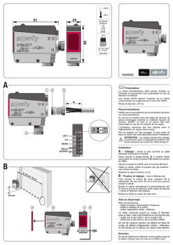
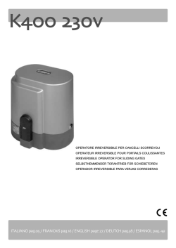
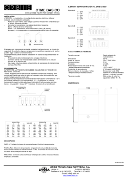
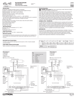
© Copyright 2026