
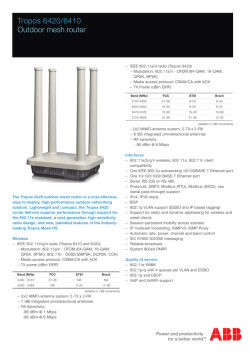
INTERNATIONAL STANDARD IEC 61968-3
INTERNATIONAL STANDARD IEC 61968-3 First edition 2004-03 Application integration at electric utilities – System interfaces for distribution management – Part 3: Interface for network operations Reference number IEC 61968-3:2004(E) Publication numbering As from 1 January 1997 all IEC publications are issued with a designation in the 60000 series. For example, IEC 34-1 is now referred to as IEC 60034-1. Consolidated editions The IEC is now publishing consolidated versions of its publications. For example, edition numbers 1.0, 1.1 and 1.2 refer, respectively, to the base publication, the base publication incorporating amendment 1 and the base publication incorporating amendments 1 and 2. Further information on IEC publications The technical content of IEC publications is kept under constant review by the IEC, thus ensuring that the content reflects current technology. Information relating to this publication, including its validity, is available in the IEC Catalogue of publications (see below) in addition to new editions, amendments and corrigenda. Information on the subjects under consideration and work in progress undertaken by the technical committee which has prepared this publication, as well as the list of publications issued, is also available from the following: • IEC Web Site (www.iec.ch) • Catalogue of IEC publications The on-line catalogue on the IEC web site (www.iec.ch/searchpub) enables you to search by a variety of criteria including text searches, technical committees and date of publication. On-line information is also available on recently issued publications, withdrawn and replaced publications, as well as corrigenda. • IEC Just Published This summary of recently issued publications (www.iec.ch/online_news/ justpub) is also available by email. Please contact the Customer Service Centre (see below) for further information. • Customer Service Centre If you have any questions regarding this publication or need further assistance, please contact the Customer Service Centre: Email: [email protected] Tel: +41 22 919 02 11 Fax: +41 22 919 03 00 INTERNATIONAL STANDARD IEC 61968-3 First edition 2004-03 Application integration at electric utilities – System interfaces for distribution management – Part 3: Interface for network operations IEC 2004 Copyright - all rights reserved No part of this publication may be reproduced or utilized in any form or by any means, electronic or mechanical, including photocopying and microfilm, without permission in writing from the publisher. International Electrotechnical Commission, 3, rue de Varembé, PO Box 131, CH-1211 Geneva 20, Switzerland Telephone: +41 22 919 02 11 Telefax: +41 22 919 03 00 E-mail: [email protected] Web: www.iec.ch Com mission Electrotechnique Internationale International Electrotechnical Com m ission Международная Электротехническая Комиссия PRICE CODE For price, see current catalogue W –2– 61968-3 IEC:2004(E) CONTENTS FOREWORD...........................................................................................................................4 INTRODUCTION.....................................................................................................................6 1 Scope ...............................................................................................................................7 2 Normative references .......................................................................................................7 3 Reference and information models ...................................................................................8 4 3.1 General ...................................................................................................................8 3.2 Interface reference model........................................................................................8 3.3 Network operations functions and components ........................................................8 3.4 Message type terms .............................................................................................. 10 3.5 Static information model ........................................................................................ 11 Message types – General ............................................................................................... 14 5 4.1 Message usage ..................................................................................................... 14 4.2 Compliance ........................................................................................................... 14 4.3 Message formats ................................................................................................... 14 4.4 Common message type fields ................................................................................ 14 Network operations message types ................................................................................ 20 5.1 5.2 5.3 5.4 5.5 5.6 5.7 Summary............................................................................................................... 20 Measurement list message types........................................................................... 20 OperationalRestriction message types................................................................... 28 OutageRecord message types ............................................................................... 30 SafetyDocument message types............................................................................ 32 SwitchingSchedule Message message types ......................................................... 33 Message format..................................................................................................... 33 Annex A (informative) Description of message type verbs .................................................... 35 Figure 1 – Simplified operational documents model .............................................................. 11 Figure 2 –Generic pattern used for all message types........................................................... 15 Figure 3 – Example (informative) of a control area used for all message types ..................... 15 Figure 4 – Naming class ....................................................................................................... 16 Figure 5 – Document associations ........................................................................................ 17 Figure 6 – Document Class class details............................................................................... 18 Figure 7 – Person and role played by person relative to a document..................................... 19 Figure 8 – Person and role played by person relative to an organisation ............................... 20 Figure 9 – Measurement list message format ........................................................................ 21 Figure 10 – Continuation of measurement list message format ............................................. 22 Figure 11 – Measurement list – Measurement details............................................................ 23 Figure 12 – Continuation of Measurement list – Measurement details ................................... 24 Figure 13 – Measurement list – Control details ..................................................................... 25 Figure 14 – Continuation of Measurement list – Control details ............................................. 26 Figure 15 – Operational restriction message format .............................................................. 29 Figure 16 – Outage record message format .......................................................................... 31 Figure 17 – Outage record – Outage step details ................................................................ 32 Figure 18 – Switching schedule message format................................................................... 34 61968-3 IEC:2004(E) –3– Table 1 – Document overview for IEC 61968-3 .......................................................................6 Table 2 – Business functions for network operations ...............................................................9 Table 3 – Classes for Network Operations ............................................................................ 12 Table 4 – Classes related to network operations ................................................................... 13 Table 5 – Recommended measurement names ..................................................................... 26 Table A.1 – Commonly used verbs ........................................................................................ 35 61968-3 IEC:2004(E) –4– INTERNATIONAL ELECTROTECHNICAL COMMISSION ____________ APPLICATION INTEGRATION AT ELECTRIC UTILITIES – SYSTEM INTERFACES FOR DISTRIBUTION MANAGEMENT – Part 3: Interface for network operations FOREWORD 1) The International Electrotechnical Commission (IEC) is a worldwide organization for standardization comprising all national electrotechnical committees (IEC National Committees). The object of IEC is to promote international co-operation on all questions concerning standardization in the electrical and electronic fields. To this end and in addition to other activities, IEC publishes International Standards, Technical Specifications, Technical Reports, Publicly Available Specifications (PAS) and Guides (hereafter referred to as “IEC Publication(s)”). Their preparation is entrusted to technical committees; any IEC National Committee interested in the subject dealt with may participate in this preparatory work. International, governmental and nongovernmental organizations liaising with the IEC also participate in this preparation. IEC collaborates closely with the International Organization for Standardization (ISO) in accordance with conditions determined by agreement between the two organizations. 2) The formal decisions or agreements of IEC on technical matters express, as nearly as possible, an international consensus of opinion on the relevant subjects since each technical committee has representation from all interested IEC National Committees. 3) IEC Publications have the form of recommendations for international use and are accepted by IEC National Committees in that sense. While all reasonable efforts are made to ensure that the technical content of IEC Publications is accurate, IEC cannot be held responsible for the way in which they are used or for any misinterpretation by any end user. 4) In order to promote international uniformity, IEC National Committees undertake to apply IEC Publications transparently to the maximum extent possible in their national and regional publications. Any divergence between any IEC Publication and the corresponding national or regional publication shall be clearly indicated in the latter. 5) IEC provides no marking procedure to indicate its approval and cannot be rendered responsible for any equipment declared to be in conformity with an IEC Publication. 6) All users should ensure that they have the latest edition of this publication. 7) No liability shall attach to IEC or its directors, employees, servants or agents including individual experts and members of its technical committees and IEC National Committees for any personal injury, property damage or other damage of any nature whatsoever, whether direct or indirect, or for costs (including legal fees) and expenses arising out of the publication, use of, or reliance upon, this IEC Publication or any other IEC Publications. 8) Attention is drawn to the Normative references cited in this publication. Use of the referenced publications is indispensable for the correct application of this publication. 9) Attention is drawn to the possibility that some of the elements of this IEC Publication may be the subject of patent rights. IEC shall not be held responsible for identifying any or all such patent rights. International Standard IEC 61968-3 has been prepared by IEC technical committee 57: Power systems management and associated information exchange. The text of this standard is based on the following documents: FDIS Report on voting 57/694/FDIS 57/714/RVD Full information on the voting for the approval of this standard can be found in the report on voting indicated in the above table. This publication has been drafted in accordance with the ISO/IEC Directives, Part 2. 61968-3 IEC:2004(E) –5– IEC 61968 consists of the following parts under the general title Application integration at electric utilities – System interfaces for distribution management: Part 1: Interface architecture and general requirements Part 2: Glossary Part 3: Interface for network operations Part 4: Interface for records and asset management 1 The committee has decided that the contents of this publication will remain unchanged until 2006. At this date, the publication will be • • • • reconfirmed; withdrawn; replaced by a revised edition, or amended. A bilingual version of this publication may be issued at a later date. ——————— 1 Under consideration. –6– 61968-3 IEC:2004(E) INTRODUCTION The IEC 61968 series of standards is intended to facilitate inter-application integration as opposed to intra-application integration. Intra-application integration is aimed at programs in the same application system, usually communicating with each other using middleware that is embedded in their underlying runtime environment, and tends to be optimised for close, realtime, synchronous connections and interactive request/reply or conversation communication models. IEC 61968, in contrast, is intended to support the inter-application integration of a utility enterprise that needs to connect disparate applications that are already built or new (legacy or purchased applications), each supported by dissimilar runtime environments. Therefore, these interface standards are relevant to loosely coupled applications with more heterogeneity in languages, operating systems, protocols and management tools. This series of standards is intended to support applications that need to exchange data every few seconds, minutes, or hours rather than waiting for a nightly batch run. This series of standards, which are intended to be implemented with middleware services that exchange messages among applications, will complement, but not replace utility data warehouses, database gateways, and operational stores. As used in IEC 61968, a Distribution Management System (DMS) consists of various distributed application components for the utility to manage electrical distribution networks. These capabilities include monitoring and control of equipment for power delivery, management processes to ensure system reliability, voltage management, demand-side management, outage management, work management, automated mapping and facilities management. Standard interfaces are defined for each class of applications identified in the Interface Reference Model (IRM), which is described in IEC 61968-1. This Part of IEC 61968 contains the Clauses shown in Table 1. Table 1 – Document overview for IEC 61968-3 Clause Title Purpose 1 Scope The scope and purpose of the document are described. 2 Normative references Documents that contain provisions which, through reference in this text, constitute provisions of this International Standard. 3 Reference and information models Description of the relevant parts of the interface reference model, static information model and message type naming convention. 4 Message types – general Requirements common to all message types described in Clause 5. 5 Network operations message types Message types related to the exchange of information for operational documents namely operation restrictions, outage, safety and switching schedule. Message type verbs Description of the verbs that are used for the message types. Annex A 61968-3 IEC:2004(E) –7– APPLICATION INTEGRATION AT ELECTRIC UTILITIES – SYSTEM INTERFACES FOR DISTRIBUTION MANAGEMENT – Part 3: Interface for network operations 1 Scope The IEC 61968 series, taken as a whole, defines interfaces for the major elements of an interface architecture for Distribution Management Systems (DMS). IEC 61968-1 identifies and establishes requirements for standard interfaces based on an Interface Reference Model (IRM). Parts 3 to 10 of the IEC 61968 series define interfaces relevant to each of the major business functions described by the Interface Reference Model. As used in the IEC 61968 series, a DMS consists of various distributed application components for the utility to manage electrical distribution networks. These capabilities include monitoring and control of equipment for power delivery, management processes to ensure system reliability, voltage management, demand-side management, outage management, work management, automated mapping and facilities management. The IEC 61968 series is limited to the definition of interfaces and is implementation independent. It provides for interoperability among different computer systems, platforms, and languages. Methods and technologies used to implement a functionality conforming to these interfaces are considered outside of the scope of the IEC 61968 series; only the interface itself is specified in these standards. This part specifies the information content of a set of message types that can be used to support many of the business functions related to network operations. Typical uses of the message types defined in this part include data acquisition by external systems, fault isolation, fault restoration, trouble management, maintenance of the plant, and the commissioning of the plant. An additional part of IEC 61968 will document integration scenarios or use cases, which are informative examples showing typical ways of using the message types defined in this document as well as message types to be defined in other parts of the IEC 61968 series. 2 Normative references The following referenced documents are indispensable for the application of this document. For dated references, only the edition cited applies. For undated references, the latest edition of the referenced document (including any amendments) applies. IEC 61850-7-4:2003, Communication networks and systems in substations – Part 7-4: Basic communication structure for substation and feeder equipment – Compatible logical node classes and data classes IEC 61968-1, System interfaces for distribution management – Part 1: Interface architecture and general requirements –8– 3 3.1 61968-3 IEC:2004(E) Reference and information models General The message types defined in this document are based on a logical partitioning of the DMS business functions and components called the IEC 61968 interface reference model. The contents of the message types are based on a static information model to ensure consistency of field names and data types. Each message type is defined as a set of fields copied from Common Information Model (CIM) classes. The message types defined in this standard are intended to satisfy a majority of typical applications. In some project implementations, it may be desirable to modify the set of fields using a methodology such as that described in IEC 61968-1. 3.2 Interface reference model It is not the intention of this standard to define the applications and systems that vendors should produce. It is expected that a concrete (physical) application will provide the functionality of one or more abstract (logical) components as listed in this standard. These abstract components are grouped by the business functions of the interface reference model. In this standard, the term abstract component is used to refer to that portion of a software system that supports one or more of the interfaces defined in Parts 3 to 10 of the IEC 61968 series. It does not necessarily mean that compliant software is delivered as separate modules. IEC 61968-1 describes infrastructure services common to all abstract components whilst Parts 3 to 10 of the IEC 61968 series define the details of the information exchanged for specific types of abstract component. The IEC 61968 series defines that: a) An inter-application infrastructure is compliant if it supplies services defined in IEC 619681 to support at least two applications with interfaces compliant to IEC 61968 Parts 3 to 10. b) An application interface is compliant if it supports the interface standards defined in IEC 61968 Parts 3 to 10 for the relevant abstract components defined in the interface reference model. c) An application is only required to support interface standards of the applicable components listed under abstract components. It is not required to support interfaces required by other abstract components of the same business sub-function or within the same business function. While this standard primarily defines information exchanged among components in different business functions, it will occasionally also define information exchanged among components within a single business function when a strong market need for this capability has been realised. 3.3 Network operations functions and components The message types defined in IEC 61968-3, may be sent or received by any type of component within a DMS system. Table 2 shows these functions and typical abstract components that are expected to be producers of information for these message types. Typical consumers of the information include, but are not restricted to, the other components as listed in IEC 61968-1; for example, geographic information systems, energy management systems and customer information systems. 61968-3 IEC:2004(E) –9– Table 2 – Business functions for network operations Business Functions Network operation (NO) Business Abstract components sub-functions Network operation Substation state supervision Monitoring (NMON) Network state supervision for example by topology processing and network colouring Switching action supervision Management of data acquired from SCADA and metering systems Management of data acquired through operation (field crews, customers, scheduled and unscheduled outages) Alarm management including supervision, acknowledgement, and deletion Operator and event logs Network control (CTL) User access control Automatic controls: Protection (fault clearance) Sectionalising Local voltage/reactive power control Assisted control: Remote switch control Load shedding Voltage regulation for example broadcast of voltage reduction command Local control through field crews Safety document management Safety checking and interlocks Major incident co-ordination Fault management (FLT) Trouble call handling and coherency analysis (LV network) Protective relays analysis Fault location by analysis of fault detectors and/or trouble call localisation Supply restoration assessment Customer incident information Operation feedback Analysis (OFA) Mal-operation analysis Network fault analysis Quality index analysis Device operation history Post-disturbance review Operation statistics and Reporting (OST) Maintenance information Network calculations – real-time (CLC) Load estimation Information for planning Information for management control Energy trading analysis Load flow/voltage profile Fault current analysis Adaptive relay settings Dispatcher training (TRN) SCADA simulation – 10 – 3.4 61968-3 IEC:2004(E) Message type terms The message types defined in this standard are described using the following terms. Message type name Each message type has a name consisting of a verb and a noun. Message type verb The verb describes the purpose of the message. (See Annex A for the description of the verbs). Message type noun The noun describes the type of data in the message body. Each noun corresponds to a class name in the static information model. For most message types, the nouns are a type of document. Message body The body of each message type is based on the attributes (fields) of the classes described by the nouns. Naming "Naming" is a class that defines common attributes used to identify instances of common information model classes. The attributes are a set of human readable alphanumeric strings. It is usual for utilities to use unique alphanumeric codes to identify their substations and the equipment in each substation. In some implementations, these codes may have to be prefixed with additional characters to guarantee uniqueness across organisation boundaries. Naming.name This is a human readable alphanumeric string that identifies an entity with a specific scope, for example within a particular substation. Naming.pathname This is a human readable alphanumeric string that identifies an entity with global scope, for example a concatenation of zone, substation and equipment names. Naming.aliasname This is an alternative name that is expected to be used to contain other identifiers, for example a machine allocated identification number. The aliasname may be used by a computer system as an index to name translation tables when information is exchanged between different organisations. Naming.description This is a human readable alphanumeric string that provides additional information but is not intended for automatic processing by computer systems. Document "Document" is a class that defines common attributes used in all message types. Document.type The document type is the name of the class that is the actual instance, for example "SwitchingSchedule", "ActivityRecord". Document.subtype This is additional information that may be utility specific, for example "Planned", "OnDemand" for SwitchingSchedule, "Planned", "Unplanned" for OutageRecords, "PermitToWork" for a SafetyDocument. Document.status The document status is a string indicating the status of the document. This is expected to be specific to the document type, for example "Draft", "In Progress", "Approved". 61968-3 IEC:2004(E) 3.5 – 11 – Static information model The information model relevant to network operations consists of classes that provide a template for the attributes for each message. The classes are defined in detail in another part of IEC 61968. 3.5.1 Operational documents model The message types are based on a common model of a document that includes information on the person (ErpContact) and organisation that created and/or modified the document. Operational documents inherit from the base document class and have associations with other classes such as PowerSystemResource or Asset. ErpContact Document Organisation SafetyDocument SwitchingSchedule OutageRecord 1..n OperationalRestriction SwitchingStep 1..n OutageStep IEC 176/04 Figure 1 – Simplified operational documents model 3.5.2 Classes for network operations Table 3 lists classes that are used within message types. Usually all the attributes of these classes are contained within a message type. Classes described as type "document" are top-level container entities. Message type names are based on these entities. Classes described as type "part" are lower level entities that are associated with a containing document. 61968-3 IEC:2004(E) – 12 – Table 3 – Classes for Network Operations Class name ActivityRecord Type Document Description A general purpose document that provides a chronological list of textual remarks. An ActivityRecord may be used to describe events and actions taken to restore an outage. MeasurementValueList Document A document providing header information for a list of measurement values. MeasurementValue Part The name, value, quality and timestamp for a measurement. OutageRecord Document A document describing details of an outage in part of the distribution network. An OutageRecord is typically produced as part of a planned activity (for example work order for maintenance) or following a breaker trip detected by SCADA or within a trouble call system by grouping customer calls. OutageStep Part An outage step lists each supply point, for example distribution transformer or metered switch, that is affected by an outage defined in an OutageRecord document. OperationalRestriction Document A document describing how one or more items of a plant should be operated at less than the manufacturers' ratings. It is assumed that these messages are in the network operations domain and hence are associated with power system resources only. Cross-referencing of assets to PowerSystemResources is covered by the GetAssetList, ShowAssetList message types. These are defined in another part of IEC 61968. SafetyDocument Document A document restricting or authorising works on electrical equipment, for example a permit to work, sanction for test, limitation of access, certificate of isolation. SwitchingSchedule Document A document describing a set of steps to perform an item of work for example to isolate some plant with regard to safety, equipment ratings, and standards of customer service. SwitchingStep Part A step within a SwitchingSchedule that describes a control action to be applied to an item of a plant, or a SafetyDocument to be issued or cancelled or simple text. 61968-3 IEC:2004(E) 3.5.3 – 13 – Classes related to network operations Table 4 lists those classes that are associated with network operations classes but only the name of an instance is given within messages defined in this standard. The detailed attributes of these classes are used in message types defined in other parts of IEC 61968. Table 4 – Classes related to network operations Related Class Asset Reference Description Another part of IEC 61968 covering records and asset management An entity that describes the physical view of a component part of the utility business. Assets may be classified as PointAssets for example a switch or LinearAssets for example cable sections. Crew Another part of IEC 61968 covering maintenance and construction A crew is a collection of people (ErpContacts) with specific skills, tools, and vehicles. Customer Another part of IEC 61968 covering customer support The customer class holds information about individual customers that are served electric power i.e. with a metered connection to the network. ErpContact Another part of IEC 61968 covering maintenance and construction Information about a person and their role within a utility organisation. ErpContacts may include external purchasers and suppliers of equipment and services. Organisation Another part of IEC 61968 covering records and asset management This class is used to identify companies or divisions within companies. Organisations might have roles as utilities, contractors, suppliers, manufacturers, etc. PowerSystemResource Another part of IEC 61968 covering records and asset management An entity that describes the logical view of a component part of the utility business. PowerSystemResources are further classified as EquipmentContainers for example Substations, ConductingEquipment, ProtectionEquipment etc. TroubleTicket Another part of IEC 61968 covering customer support A type of document that contains the information of one or more customer calls. Work Another part of IEC 61968 covering maintenance and construction A type of document that contains information used to request, initiate, track and record work, particularly construction and maintenance tasks. Instances of type asset may be related to instances of type PowerSystemResource. Instances of type PowerSystemResource may be related to instances of type asset. – 14 – 4 61968-3 IEC:2004(E) Message types – General This clause defines the general features of message types. Specific message types for Network Operations are covered in Clause 5. 4.1 Message usage This standard defines the format of a set of message types which applications may send or receive but does not define any particular order or interaction between messages. Typical scenarios are Request-Reply and Publish-Subscribe. See Annex A for details of standard verbs. For Request-Reply scenarios, a client application is expected to issue a Get or Create type of message and then receive a Show or Created message type in return. For the Publish-Subscribe scenarios, client applications will issue a Subscribe type of message and then receive one or more relevant Show, Created, or Changed message types asynchronously. 4.2 Compliance This standard defines the logical names of message types and fields within message types. Compliance can be assessed separately for each message type. However it is expected that vendors will offer compliance for all messages defined in this part of IEC 61968. A software component is deemed to be compliant to any specific message type if a) The component can produce an XML message for a message type including all required fields with names and data types as defined in this standard. Data may be set to a default value if it is not available within a component. Optional data shall be passed in the appropriate optional fields. Message type extensions are compliant as long as the correct CIM fields are used when applicable. b) The component can read an XML message produced for a message type defined in this standard and correctly interpret the fields in the message. 4.3 Message formats In general, message types have been defined with fields that may hold different representations of the same data. It is expected that producer applications will set some fields with default null values. In the message format descriptions, message elements ending in “Seg,” such as “DocumentSeg,” mean that instance data may be provided for some or all of the attributes of that class in the static information model. Elements that are required have solid line boxes around them whereas option elements have dashed line boxes. When an element may have an unlimited number of instances, this is indicated by the expression [0..∞]. 4.4 Common message type fields The following subclauses describe the fields that shall be part of all message types defined in this standard. 4.4.1 Message organisation In accordance with IEC 61968-1, message types are organized according to the generic pattern shown in Figure 2. The message payload, on the other hand, is normative and is the primary subject matter of this standard. It is described in the remaining clauses. 61968-3 IEC:2004(E) – 15 – IEC 177/04 Figure 2 –Generic pattern used for all message types The control area contains the message type verb, noun, revision, and other information about the message. The control area shown in Figure 3 is for illustrative purposes; it is informative as it varies according to the specific implementation technologies. Appropriate verbs are listed in Annex A. IEC 178/04 Figure 3 – Example (informative) of a control area used for all message types 4.4.2 Namespaces Each message attribute name has a prefix called a namespace. This provides an extendable way of indicating the design authority for particular attributes. The cim: namespace is reserved for attributes defined explicitly within the Common Information Model (CIM). The cs: namespace is used to specify the CIM segment groupings. If message type formats are customised by software suppliers or for specific utilities, then any additional attributes shall be prefixed with different namespaces. To support this, the ce: namespace is used for custom extensions. – 16 – 4.4.3 61968-3 IEC:2004(E) Naming class Most IEC 61970 and IEC 61968 CIM classes inherit from the Naming class (depicted in Figure 4) which provides a consistent way of identifying instances. This scheme is compatible with the generic eventing services that will be defined in part of IEC 61970. IEC 179/04 Figure 4 – Naming class This notation shows that the NamingSeg is defined as an instance of NamingSegmentType, which contains four attributes from the CIM. Naming.name is mandatory as indicated by the solid line. The other three attributes are optional, indicated by the dotted line. 4.4.4 Document class The Document class defines common attributes used in all message types. See 3.4. The document and its associations is shown in Figure 5. 61968-3 IEC:2004(E) – 17 – Figure 5 – Document associations IEC 180/04 The Document Class inherits from the Naming Class and, in similar fashion as PowerSystemResource and Asset, is the top of a large hierarchy. At the root of many utility real world objects is a type of document. Definitions of relevant classes, which are any elements beginning with the “cs” namespace, are made in another part of IEC 61968 covering the Distribution Information Exchange Model (DIEM). As the Document class is referenced extensively throughout this document, it is shown in Figure 6 for convenience. Note that associations between classes in the CIM are indicated with “Assoc” following the name of the source class and the destination class following the period (“.”) delimiter. For example, “cim:Document.PowerSystemResources” in DocumentSeg indicates that an instance of Document can be associated with zero to many instances of PowerSystemResource. The same pattern for various groups of information elements are frequently encountered across multiple message types; the “cg” namespace, for CIM Groups, indicates such a reusable pattern. The two such patterns referenced in Figure 5 are shown in Figures 7 and 8. – 18 – 61968-3 IEC:2004(E) IEC Figure 6 – Document Class class details 181/04 61968-3 IEC:2004(E) 4.4.5 – 19 – ErpContact and organisation roles Documents may be created or modified by several persons (ErpContact) or organisations. Some types of document may have specific roles, for example CheckedBy, ApprovedBy. As it is not practical to define an explicit association for every type of role a person may play for various types of documents, the following construct (depicted in Figure 7) that may be used to describe each relevant role a person plays for each document is provided. IEC Figure 7 – Person and role played by person relative to a document As it is not practical to define an explicit association for every type of role a person may play for various organisations, the following construct (depicted in Figure 8) is provided that may be used to describe each relevant role a person plays for each organisation. 182/04 – 20 – 61968-3 IEC:2004(E) IEC 183/04 Figure 8 – Person and role played by person relative to an organisation Note that each person, referred to as “ErpContact,” is only referenced in the elements given in Figure 8. For detailed information about the person, the <verb>ErpContact message type is used, where the verb is create, show, etc. 5 5.1 Network operations message types Summary The network operations message types describe information for the following types of document: • measurement list; • operational restrictions; • outage records; • safety documents; • switching schedules. 5.2 Measurement list message types The measurement list document is a simple way of transferring measurement value data. This is intended to complement the more comprehensive facilities for measurement data exchange that will be described in an appropriate part of IEC 61970. Measurement values may be either scalar (analogue) values or discrete keywords for status measurements. 61968-3 IEC:2004(E) 5.2.1 – 21 – Message format Created MeasurementList, changed MeasurementList and show MeasurementList have the message format shown in Figures 9 to 14. IEC Figure 9 – Measurement list message format 184/04 – 22 – 61968-3 IEC:2004(E) IEC 185/04 Figure 10 – Continuation of measurement list message format 61968-3 IEC:2004(E) – 23 – Figure 11 – Measurement list – Measurement details IEC 186/04 – 24 – 61968-3 IEC:2004(E) IEC Figure 12 – Continuation of Measurement list – Measurement details 187/04 61968-3 IEC:2004(E) – 25 – IEC Figure 13 – Measurement list – Control details 188/04 – 26 – 61968-3 IEC:2004(E) IEC 189/04 Figure 14 – Continuation of measurement list – Control details 5.2.2 Recommended measurement names Some measurement names suitable for distribution management applications are defined in IEC 61850-7-4. Table 5 shows a set of recommended measurement names. Vendors or utilities may specify additional names. Table 5 – Recommended measurement names Name Description Type Amps Current I (r.m.s.) of a non-three phase circuit Analogue TotAmps Total current I (r.m.s.) in a three phase circuit Analogue Hz Frequency (f) Analogue PwrFact Power factor (pf) Analogue TotPF Average power factor (pf) in a three phase circuit Analogue TotVA Total apparent power (S) in a three phase circuit Analogue TotVAr Total reactive power (Q) in a three phase circuit Analogue TotW Total real power (P) in a three phase circuit Analogue 61968-3 IEC:2004(E) Name VoltAmp – 27 – Description Type Apparent power (S) in a non-three phase circuit Analogue VoltAmpR Reactive power (Q) in a non-three phase circuit Analogue Volts Voltage (V) (r.m.s.) Analogue Watts Real power (P) in a non-three phase circuit Analogue Pres Pressure Analogue Temp Temperature Analogue TotAng Angle (phi) (in a three phase circuit) Analogue TotVAh Apparent energy Integer TotVArh Reactive energy Integer TotWh Real energy Integer TapPos Tap position of power transformer or phaseshifter Integer OperCnt Operation count – typically for switches Integer Auto Automatic operation (not manual). Automatic = TRUE MANUAL,AUTO Loc Local operation (not remote). Local =TRUE REMOTE,LOCAL Pos Switch position i.e. topology state IGNORE, OPEN, CLOSE, TRAVEL LTCBlk Automatic control of LTC blocked (inhibited). Blocked = TRUE FREE, BLOCKED Parallel Transformers in parallel operating mode INDEPENDENT, PARALLEL GenOperMode Generator operating mode OFF, STARTING, STOPPING, AGC, etc. VoltRegMode Voltage regulation mode OFF, MVAR, VOLT NotInService Equipment not in service INSERVICE, NIS LockAndCaution Indicates whether the equipment has had a lock and caution tag applied NONE, LKCAUTION AutoReclose Indicates whether breaker auto-reclose exists and is enabled NONE, AROFF, ARON AutoChangeOver Indicates whether this equipment has an auto-changeover scheme NONE, ACOFF, ACON BusBarSelector Indicates which bus of a double busbar is selected NONE, BUS1, BUS2 OverCurrentTrip Indicates that a breaker has tripped on over-current, or that a fault passage indicator has detected over-current NONE, OCTRIP GroundFaultTrip Indicates that a breaker has tripped for a ground fault, or that a fault passage indicator has detected a ground fault. Also known as Sensitive Earth Fault state NONE, SEFTRIP IsolationState Whether or not equipment is isolated from a source of power UNKNOWN, ISOLATED, CONNECTED AppEnergization Energization state applied to conducting equipment for example by NONE, GROUND, grounding switches or generators. Switch cabinets that may ENERGIZE, FAULT ground either a circuit or a busbar may also have a BusBarSelector state Energization Calculated or measured energization state of conducting equipment UNKNOWN, DEAD, GROUNDED, ENERGIZED, FAULTED QuotedState Indicates whether equipment is quoted on a safety document NONE, QUOTED ControlState Status of a control or command PROPOSED, INSTRUCTED, CONFIRMED, CANCELLED, SKIPPED – 28 – 5.3 61968-3 IEC:2004(E) OperationalRestriction message types An operational restriction document describes how one or more items of plant should be operated at less than the manufacturers' ratings. It is assumed that these messages are in the network operations domain and hence are associated with power system resources only. There can be a severity level associated with a restriction for example a highest form of restriction may exclude the device from any live operation. Once a restriction is applied, facilities are required to remove the restriction from all the PowerSystemResources or individually from a device. 5.3.1 General There are no general requirements. 5.3.2 Message format Created OperationalRestriction, changed OperationalRestriction, show OperationalRestriction and deleted OperationalRestriction have the same message formats as shown in Figure 15. 61968-3 IEC:2004(E) – 29 – IEC Figure 15 – Operational restriction message format 190/04 – 30 – 5.4 5.4.1 61968-3 IEC:2004(E) OutageRecord message types General An OutageRecord document describes details of an outage in part of the distribution network. An OutageRecord is typically produced as part of a planned activity (for example work order for maintenance) or following a breaker trip detected by SCADA or within a trouble call system by grouping calls from customers. OutageRecords may be created automatically following detection of breaker trip by a SCADA system. Any subsequent trouble calls may be grouped with the same OutageRecord. OutageRecords may also be created solely based on the location of trouble calls. In this case, the document status may be used to indicate whether a fault has been confirmed. An OutageRecord has an associated OutageStep for each supply point, for example distribution transformer or metered switch that is affected by the outage. This list is either calculated by topology processing of the network or from grouping of customer calls. An OutageRecord may have an associated ActivityRecord to record remarks or comments about the progress of the outage restoration process and any follow-up work. This may be presented as a chronological list of all the actions/events. To allow for different country or utility practices, an OutageRecord may refer to either crew and/or ErpContacts, for example the crew foreman. There may also be additional work associated with an outage. When this is the case, the outage may not be allowed to “close to history” until the additional work has been completed even though the supply to all affected customers has been restored. Some of the fields for example OutageStep.fatality, may be specific to particular utilities and systems. It should be noted that the Document.Comments field is available for generalpurpose text that can characterise the outage. 5.4.2 Message format Created OutageRecord, changed OutageRecord and show OutageRecord message types have the same message formats as shown in Figure 16 and 17. Get OutageRecord, canceled OutageRecord, closed OutageRecord and deleted Outage Record identify only the document name. 61968-3 IEC:2004(E) – 31 – IEC Figure 16 – Outage record message format 191/04 – 32 – 61968-3 IEC:2004(E) IEC 192/04 Figure 17 – Outage record – Outage step details 5.5 SafetyDocument message types A SafetyDocument restricts or authorises work on electrical equipment for example a permit to work, sanction for test, limitation of access, certificate of isolation. Created SafetyDocument, changed SafetyDocument and show SafetyDocument message types have same message formats as shown in Figure 18. Get SafetyDocument, canceled SafetyDocument, closed SafetyDocument, and deleted SafetyDocument identify only the document name. 61968-3 IEC:2004(E) – 33 – IEC 193/04 Figure 18 – Safety document message format 5.6 SwitchingSchedule Message message types A SwitchingSchedule document describes a set of steps to perform an item of work for example to isolate some plant with regard to safety, equipment ratings, and standards of customer service. The ScheduleStep status field has one of the following values: Proposed The control action is proposed to allow the system to check against safety rules and the effect supply status for the customers connected. Instructed The control action has been executed through telemetry or as an instruction to field crew. Confirmed The control action has been reported complete by telemetry or verbally from field crew. Aborted This step is aborted after it was instructed. Skip This step will not or has not been executed. 5.7 Message format Created SwitchingSchedule, Changed SwitchingSchedule and Show SwitchingSchedule message types have same message formats as shown in Figure 19. Get SwitchingSchedule, canceled SwitchingSchedule, closed SwitchingSchedule and deleted SwitchingSchedule message types identify only the document name. – 34 – 61968-3 IEC:2004(E) IEC Figure 19 – Switching schedule message format 194/04 61968-3 IEC:2004(E) – 35 – Annex A (informative) Description of message type verbs Table A.1 – Commonly used verbs Verbs Meaning Message body CREATE The CREATE verb is used to publish a request to the master system to create a new document. The master system may in turn publish the new document using the verb CREATED. The master system may also use the verb REPLY to respond to the CREATE request, indicating whether the request has been processed successfully or not. All sections (data required to create the document) CHANGE The CHANGE verb is used to publish a request to the master system to make a change in the document based on the information in the message. The master system may in turn publish the changed document using the verb CHANGED to notify that the document has been changed since last published. The master system may also use the verb REPLY to response to the CHANGE request, indicating whether the request has been processed successfully or not. All sections (key(s) + data to be changed) CANCEL The CANCEL verb is used to publish a request to the master system to cancel the document. The master system may in turn publish the cancelled message using the verb CANCELED to notify that the document has been cancelled since last published. The master system may also use the verb REPLY to respond to the CANCEL request, indicating whether the request has been processed successfully or not. The CANCEL verb is used when the business content of the document is no longer valid due to error(s). Header information + message content key(s) CLOSE The CLOSE verb is used to publish a request to the master system to close the document. The master system may in turn publish the closed message using the verb CLOSED to notify that the document has been closed since last published. The master system may also use the verb REPLY to respond to the CLOSE request, indicating whether the request has been processed successfully or not. The CLOSE verb is used when the business document reaches the end of its life cycle due to successful completion of a business process. Header information + message content key(s) DELETE The DELETE verb is used to publish a request to the master system to delete the document. The master system may in turn publish the closed message using the verb DELETED to notify that the document has been deleted since last published. The master system may also use the verb REPLY to respond to the DELETE request, indicating whether the request has been processed successfully or not. The DELETE verb is used when the business document should no longer be kept in the integrated systems either due to error(s) or due to archiving needs. Header information + message content key(s) GET The GET verb is used to publish a request to the master system to get the current data for a given document reference code or a set of documents. The master system may in turn publish the document using the SHOW verb, if the document is available, or use the verb REPLY to response to the GET request, indicating that the document is not available. One or more document reference codes + key(s) CREATED The CREATED verb is used to publish the creation of a document as a result of either an external request or an internal action within the master system of that document. This is the first time that data for this document reference code has been published as the result of internal or external request; in which case, it would use the same document reference as the CREATE message. This message type is usually subscribed by interested systems and could be used for mass updates. There is no need to reply to this message type. All sections – 36 – Verbs 61968-3 IEC:2004(E) Meaning Message body CHANGED The CHANGED verb is used to publish the change of a document as a result of either an external request or an internal action within the master system of that document. This could be a generic change in the content of the document or a specific status change such as “approved”, “issued”, etc. This message type is usually subscribed by interested systems and could be used for mass updates. There is no need to reply to this message type. All sections (key(s) + changed content) CLOSED The CLOSED verb is used to publish the normal closure of a document as a result of either an external request or an internal action within the master system of that document. This message type is usually subscribed by interested systems and could be used for mass updates. There is no need to reply to this message type. Header information + message content key(s) CANCELED The CANCELED verb is used to publish the cancellation of a document as a result of either an external request or an internal action within the master system of that document. This message type is usually subscribed by interested systems and could be used for mass updates. There is no need to reply to this message type. Header information + message content key(s) DELETED The DELETED verb is used to publish the deletion of a document as a result of either an external request or an internal action within the master system of that document. This message type is usually subscribed by interested systems and could be used for mass updates. There is no need to reply to this message type. Header information + message content key(s) SHOW The SHOW verb is used to publish the most current content of a document as a result of either an external GET request or an internal action within the master system of that document. This message type is usually subscribed by the requesting system(s) or other interested systems. There is no need to reply to this message type. All sections REPLY The REPLY verb is used to publish the processing result of an external request to the master system to create, change, delete, cancel, or close a document. The REPLY message type could contain specific confirmation information as to whether the request is processed successfully or not and provide alternatives if applicable. This message type is usually subscribed by the requesting systems. There is no need to reply to this message type. Header information + message content key(s) + confirmation information + alternatives (optional) SUBSCRIBE The SUBSCRIBE verb is used to publish the request to ask the master system of a document to publish a CHANGED document whenever there is a change to the document. It implies that the master system will not publish the CHANGED document unless there are one or more subscribers for the changed information. Header information + message content key(s) UNSUBSCRIBE The UNSUBSCRIBE verb is used to publish the request to ask the master system of a document to stop publishing a CHANGED document whenever there is a change to the document. It implies that the master system will not publish the CHANGED document when there are no subscribers. Header information + message content key(s) ___________ Standards Survey The IEC would like to offer you the best quality standards possible. To make sure that we continue to meet your needs, your feedback is essential. Would you please take a minute to answer the questions overleaf and fax them to us at +41 22 919 03 00 or mail them to the address below. Thank you! Customer Service Centre (CSC) International Electrotechnical Commission 3, rue de Varembé 1211 Genève 20 Switzerland or Fax to: IEC/CSC at +41 22 919 03 00 Thank you for your contribution to the standards-making process. Nicht frankieren Ne pas affranchir A Prioritaire Non affrancare No stamp required RÉPONSE PAYÉE SUISSE Customer Service Centre (CSC) International Electrotechnical Commission 3, rue de Varembé 1211 GENEVA 20 Switzerland Q1 Please report on ONE STANDARD and ONE STANDARD ONLY. Enter the exact number of the standard: (e.g. 60601-1-1) Q6 standard is out of date 4 standard is incomplete 4 standard is too academic 4 standard is too superficial 4 title is misleading 4 I made the wrong choice 4 other .................................................... ............................................................. Q2 Please tell us in what capacity(ies) you bought the standard (tick all that apply). I am the/a: purchasing agent 4 librarian 4 researcher 4 design engineer 4 safety engineer 4 testing engineer 4 marketing specialist 4 other..................................................... Q3 Q7 I work for/in/as a: (tick all that apply) manufacturing 4 consultant 4 government 4 test/certification facility 4 public utility 4 education 4 military 4 other..................................................... Q5 This standard meets my needs: (tick one) not at all nearly fairly well exactly 4 4 4 4 I read/use the: (tick one) French text only English text only both English and French texts This standard will be used for: (tick all that apply) general reference 4 product research 4 product design/development 4 specifications 4 tenders 4 quality assessment 4 certification 4 technical documentation 4 thesis 4 manufacturing 4 other..................................................... Please assess the standard in the following categories, using the numbers: (1) unacceptable, (2) below average, (3) average, (4) above average, (5) exceptional, (6) not applicable timeliness ............................................. quality of writing.................................... technical contents................................. logic of arrangement of contents .......... tables, charts, graphs, figures ............... other .................................................... Q8 Q4 If you ticked NOT AT ALL in Question 5 the reason is: (tick all that apply) Q9 4 4 4 Please share any comment on any aspect of the IEC that you would like us to know: ............................................................ ............................................................ ............................................................ ............................................................ ............................................................ ............................................................ ............................................................ ............................................................ ............................................................ ............................................................ ............................................................ ............................................................ ISBN 2-8318-7433-5 -:HSMINB=]\YX X: ICS 33.200 Typeset and printed by the IEC Central Office GENEVA, SWITZERLAND


© Copyright 2026