
Low-frequency noise in top-gated ambipolar carbon
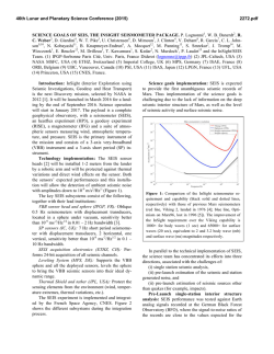
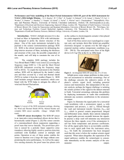
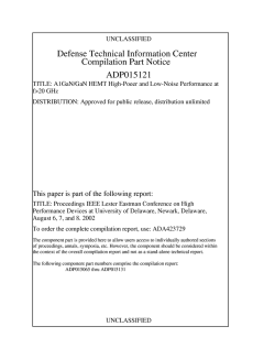
APPLIED PHYSICS LETTERS 92, 223114 共2008兲 Low-frequency noise in top-gated ambipolar carbon nanotube field effect transistors Guangyu Xu,1,a兲 Fei Liu,2 Song Han,1 Koungmin Ryu,3 Alexander Badmaev,3 Bo Lei,3 Chongwu Zhou,3 and Kang L. Wang1 1 Department of Electrical Engineering, University of California at Los Angeles, Los Angeles, California 90095, USA 2 IBM T. J. Watson Research Center, Yorktown Heights, New York 10598, USA 3 Department of Electrical Engineering, University of Southern California, Los Angeles, California 90089, USA 共Received 27 February 2008; accepted 19 May 2008; published online 6 June 2008兲 Low-frequency noise of top-gated ambipolar carbon nanotube field effect transistors 共CNT-FETs兲 with aligned CNT growth onto the quartz substrate is presented. The noise of top-gated CNT-FETs in air is lower than that of back-gated devices, and is comparable to that of back-gated devices in vacuum. It shows that molecules in air act as additional scattering sources, which contribute to the noise. Different noise amplitudes in the electron-conduction and the hole-conduction regions are due to different Schottky barriers with respect to the conduction and valance bands as well as the scattering in the channel. © 2008 American Institute of Physics. 关DOI: 10.1063/1.2940590兴 To date, most of research on carbon nanotube field effect transistors 共CNT-FETs兲 has been focused for their low power consumption and energy delay products.1–4 As the device size keeps scaling down, channel scattering and contact properties increasingly impact the device performance. Back-gated CNT-FET structure without passivation has been found to be sensitive to interface defects and/or air molecules.5,6 Hence, the reduction of the low-frequency noise level has become an essential issue in realizing CNTFET for practice use. Top-gated FET structure is a natural choice for realistic electronic systems. The Al2O3 gate dielectric acting as a passivation layer to the p-type CNT-FETs has been shown to stabilize their electrical characteristics, and to lower the noise of the drain-to-source CNT resistance on a Si/ SiO2 substrate without gate bias.7 However, the CNT synthesis on the Si/ SiO2 substrate normally cannot control the CNT growth direction and the device structure has large parasitic capacitances, which limits their use for manufacturable CNT integrated circuits.8 Recently reported high performance devices were realized by using aligned CNT growth on the quartz substrate.8,9 With the aligned CNT in a controllable direction, it is possible to reduce the crossover and misalignment among CNTs. Investigations on noise performance of this top-gated structure device will be helpful in designing CNT-FETs with a good signal to noise ratio for potential device and circuit integrations. In this work, the noise power spectrum density 共PSD兲 was measured using Agilent 35670A after the signal was passed through a low noise operational amplifier; a Keithley 4200 was used for device characterization under bias. Top-gated CNT-FETs reported here were fabricated onto a 500 m thick quartz substrate shown in the inset of Fig. 1共a兲. The aligned growth of single-walled CNTs was achieved using a chemical vapor deposition method.8 The source/drain contacts of different widths were made by deposition of Ti/ Au metal films 共3 / 50 nm兲. The carrier transport of the devices was believed to be within the diffusive limit a兲 Electronic mail: [email protected]. 0003-6951/2008/92共22兲/223114/3/$23.00 since the channel length was as long as 4 m.10 The density of CNTs was roughly 4 CNTs/ m of the channel width, with the diameters varying from 1 to 2 nm as observed in the scanning electron micrograph 共SEM兲 inset. A 24 nm HfO2 gate oxide was deposited by atomic layer deposition, followed by depositing a 2 m Au gate electrode defined by ebeam writing in the middle between the source and drain. Figure 1共a兲 also shows the typical ambipolar transfer characteristics of a top-gated CNT-FET. Since both metallic and semiconducting CNT channels were present, a burning process was used to remove metallic ones. In the burning process, Vds was increased in order to burn metallic CNT FIG. 1. 共Color online兲 共a兲 Typical ambipolar transfer characteristics of topgated CNT-FET with Vds = 0.5 V at room temperature. Inset: the schematic of the device and the SEM picture of the aligned CNTs 共bright lines兲 grown on the quartz substrate. 共b兲 Typical noise PSD in air under room temperature at Vg = 3 V vs Vds, showing a typical 1 / f behavior. The solid line shows the normalized 1 / f noise scaled to SI = 10−18 A2 / Hz at f = 100 Hz. 92, 223114-1 © 2008 American Institute of Physics 223114-2 Xu et al. FIG. 2. 共Color online兲 共a兲 Noise amplitudes 共A兲 and current 共Ids兲 under different gate biases near f = 40 and 640 Hz in both the electron-conducting 共n兲 and the hole-conducting 共p兲 regions. Transfer characteristics 共Ids-Vg兲 for both regions are plotted in the same scale on the left. The noise amplitudes for both regions are inversely related to the drain current. 共b兲 Noise amplitudes 共A兲 under different source-drain biases for f = 640 Hz for both regions 共on the left scale兲. Ids-Vds curves are also shown with Vds ranging from 0.05 to 0.75 V 共on the right scale兲. Inset: a different trend of the noise dependence on Vds is attributed to SBs with respect to the conduction band 共n-region兲 and valance band 共p-region兲. channels. After the burning process, the Ion / Ioff current ratio was improved.9 Ion was typically observed to change from 1 – 10 A to 0.001– 0.1 A before and after the burning process, respectively. However, the effective CNT density was reduced. Experiments were done for six CNT-FET devices but all the data shown in this paper came from the same device. In testing, five out of six devices show ambipolar characteristics while one device shows only p-type characteristics with the applied gate bias typically ranging from −4 to 4 V. The gate leakage current was generally observed in the range of 0.1– 1 pA. Figure 1共b兲 shows typical room temperature noise PSD for the frequency range from 25 to 800 Hz for Vg = 3 V 共n-region兲, and Vds varying from 0.10 to 0.75 V. Measurements were made in air. A hysteresis effect 共a threshold shift is less than 1 V兲 was observed. Noise data after subtracting the background were collected by a similar method as before.10 The low-frequency noise shows 1 / f ␣ behavior for the frequency range from 0.125 Hz to 25.6 kHz 共not shown兲 with ␣ ranging from 1.02 to 1.23. The deviation of the 1 / f shape is probably due to other noise mechanisms such as a random telegraph signal from an individual scattering trap, which has a Lorenzian noise characteristic of its own.11 The noise amplitude A is defined as A = SI共f / I2兲 since all devices show typical 1 / f noise behavior in both n and p regions. Figure 2共a兲 shows part of the Ids-Vg relationship for the ambipolar device at Vds = 0.5 V, where the currents were collected at the same time with the noise. The noise amplitude data 共A兲 approximately at f = 40 Hz and f = 640 Hz for both regions are shown to be inversely related to the drain Appl. Phys. Lett. 92, 223114 共2008兲 current Ids. This trend is similar to those reported in wide ranges of nanotube conductors, where the noise amplitude is inversely related to the sample conductance.12 For the p-region with Vg ranging from −4 to− 2 V, A and Ids show two and three orders of change, respectively, which is consistent with four orders of change of the total noise level 共SI兲 共not shown兲. For the n-region with Vg ranging from 1 to 3 V, the variation of noise amplitude 共A兲 with Vg are smoother than those in the p-region since both Ids and SI change less than one-order. In general, while it is still not clear about the gate dependence to the noise performance for certain CNTFET structures, it is observed here that as the gate bias is biased to the subthreshold regime, the noise amplitude A becomes larger. It may be due to a smaller sample conductance when the device operates closer to the subthreshold regime, where a higher relative current fluctuations 共⌬Ids / Ids兲 from both the channel scattering and Schottky barrier 共SB兲 contact transmission coefficient happen.5 Figure 2共b兲 shows the dependence of the noise amplitude to the source-drain bias, Vds, for the n-region 共Vg = 3 V兲 and the p-region 共Vg = −4 V兲, respectively 共shown in the inset兲. The Ids-Vds curve at Vg = 3 V is shown to be linear, indicating that the contact is almost Ohmic due to a small SB width to the conduction band for electron conduction. On the other hand, the Ids-Vds curve at Vg = −4 V shows a typical SB characteristics, which is due to the larger SB width to the valence band for the hole conduction. The noise amplitude for f = 640 Hz is presented. For the n-region at Vg = 3 V, the noise amplitude is generally less than 2 ⫻ 10−5, roughly in the same order of amplitude with increasing Ids, similar to back-gated devices biased in the linear region.10 For the p-region at Vg = −4 V, the noise amplitude decreases from 10−3 to 10−5 with increasing Ids while approaching the same order as the n-region at Vg = 3 V. This is due to the decreasing SB contact resistance with an increasing Vds for the p-region, lowering the corresponding noise amplitude. From an earlier work,6 this noise amplitude is also attributed to the channel scattering, which causes the current fluctuation in the device. It is noted that the sample conductance increases with Vds for the p-region 共Vg = −4 V兲, where the transmission coefficient of the SB contact is approaching to be near unity. Hence the noise is almost all due to the channel scattering, and is in the same order of magnitude for both regions, as seen in Fig. 2共b兲 for large Vds. The different trend of the noise dependence on Vds for both regions is most likely due to different SB widths with respect to the conduction band and valance band. For comparison of noise levels for different CNT-FET devices, Fig. 3 shows the A − Rds for the devices of this work along with those reported in previous references.5,6,10,12,13 The detailed descriptions of CNT-FET structures in comparison are listed in Table I.14 In the linear Ids-Vds regime, the sample resistance Rds is defined as Vds / Ids. Typical points are picked from the published data and our measurements from all six devices. The noise amplitude in the top-gated CNTFETs of this work in air is shown to be lower compared to that of the back-gated devices in air, while roughly the same as that of the back-gated devices in vacuum. It suggests that molecules in air act as additional scattering sources to contribute to the noises. The HfO2 high-k top-gated CNT-FETs in this work shows one to two orders of amplitude lower in the noise amplitude 共A兲 than a reported p-type Al2O3 high-k 223114-3 Appl. Phys. Lett. 92, 223114 共2008兲 Xu et al. FIG. 3. 共Color online兲 Noise amplitude of this work 共below the dashed line兲 and other previous works 共Refs. 5, 6, 10, 12, and 13兲. The A − Rds relationships are plotted with the sample resistance Rds ranging from 105 to 1010 ⍀. Typical points are picked from the published data and our measurements for six devices in the linear region 共the deviation of linearity is smaller than 10%兲. The noise amplitude in the devices of this work in air is shown to be lower compared to that of the back-gated devices in air, while it is roughly the same as that of the back-gated devices in vacuum. top-gated device near Rds = 4 ⫻ 106 ⍀, which might be due to better high-k dielectric quality, the improved contact properties, and the large channel length13 共see a later discussion兲. The noise amplitude generally increases with Rds, which is similar to reported CNT devices.15 Our devices have a one to two orders of magnitude lower sample conductance than previous work,5,10 which may be due to the burning process and small gate biases. The impact of channel length to the noise amplitude is qualitatively discussed below. Table I shows the noise amplitudes of different CNT-FETs near Rds = 107 ⍀, with the channel length 共l兲 ranging from 600 nm to 4 m. The Rds of CNT-FETs is generally expressed as Rds = RSB + 共h / 4e2兲共l / 兲, where RSB is the contact resistance and is the electron mean free path.5 Hence, Rds with decreasing channel length should become more contact dominated. It is known that RSB is generally sensitive to both the electric field at the contact TABLE I. Details of CNT-FETs listed in Fig. 3. The noise amplitude 共A兲 from different pieces of work is shown for Rds ⬇ 107 ⍀ for comparison. BG and TG stand for back-gated and top-gated CNT-FETs, respectively. Data source Contact Structure Lchannel Exposure A 共Rds ⬇ 107 ⍀兲 Lin et al.a Lin et al.a Lin et al.b Liu et al.c Liu et al.c Reza et al.d Appenzeller et al.e Appenzeller et al.e Here Pd Ti Ti Ti/ Au Ti/ Au Pd BG BG BG BG BG BG 600 nm 300 nm 600 nm 4 m 4 m 1 m Air K vapor Air Air Vacuum Air 5 ⫻ 10−3 1 ⫻ 10−3 2 ⫻ 10−3 8 ⫻ 10−4 5.33⫻ 10−4 2.2⫻ 10−2 TG 共Al2O3兲 200 nm Air 6 ⫻ 10−3 BG TG 共HfO2兲 Air Air 1 ⫻ 10−3 4.33⫻ 10−4 a Reference 5. Reference 6. c Reference 10. d Reference 12. e Reference 13. b Pd Ti Ti/ Au 600 nm 4 m and the adsorbed gases.16 Hence, the noise of those devices with a shorter channel length will be more related to the contact geometry and the exposure in air, which will in turn, significantly impacts RSB. Through the comparison, however, it is noted that the noise amplitude may also be determined by other factors which alter the sample conductance such as scattering due to air molecules, the CNT-oxide interface quality and other contact properties. For example, it is shown that the back-gated device in Ref. 10 has the same channel length 共l = 4 m兲 and contact material 共Ti/ Au兲 with a similar HfO2 top-gated FET reported here, while the top-gated devices still show a smaller noise amplitude than the backgated devices because of the high-k dielectric passivation. In addition, the Pd contacted back-gated device in Ref. 12 has a longer channel length 共l = 1 m兲 than Ti contacted backgated devices in Ref. 13 共l = 600 nm兲, while the Pd contacted devices have a much higher noise amplitude due to the contact properties. Hence, a comprehensive study of the device dimension, contact engineering and the channel passivation is needed for low noise CNT-FET designs. In summary, the low-frequency noise level of top-gated CNT-FETs was shown to be lower compared to those of back-gated devices in air, and roughly the same as that of back-gated devices in vacuum. This result shows that attached molecules in air act as the additional scattering sources of the noise. Different noise behaviors in both n and p regions were due to different SBs with respect to the conduction band and valance band as well as the channel scattering. This device offers a low noise CNT-FET structure with potentially high on currents. We acknowledge experimental help from X. Han and M. Bao. This work was in part supported by MARCO Focus Center on Functional Engineered Nano Architectonics 共FENA兲, monitored by Dr. Betsy Weitzman. A. Javey, J. Guo, Q. Wang, M. Lundstrom, and H. J. Dai, Nature 共London兲 424, 654 共2003兲. J. Kong, N. R. Franklin, C. Zhou, M. G. Chapline, S. Peng, K. Cho, and H. Dai, Science 287, 622 共2000兲. 3 P. G. Collins, K. Bradley, M. Ishigami, and A. Zettle, Science 287, 1801 共2000兲. 4 S.-H. Hur, O. O. Park, and J. A. Rogers, Appl. Phys. Lett. 86, 243502 共2005兲. 5 Y. M. Lin, J. Appenzeller, J. Knoch, Z. H. Chen, and Ph. Avouris, Nano Lett. 6, 930 共2006兲. 6 Y. M. Lin, J. Appenzeller, Z. H. Chen, and Ph. Avouris, Physica E 共Amsterdam兲 37, 72 共2007兲. 7 S. K. Kim, Y. Xuan, P. D. Ye, S. Mohammadi, J. H. Back, and M. Shim, Appl. Phys. Lett. 90, 163108 共2007兲. 8 X. L. Liu, S. Han, and C. W. Zhou, Nano Lett. 6, 34 共2006兲. 9 S. J. Kang, C. Cocabas, T. Ozel, M. Shim, N. Pimparcar, M. A. Alam S. V. Rotkin, and J. A. Rogers, Nat. Nanotechnol. 2, 230 共2007兲. 10 F. Liu, K. L. Wang, D. H. Zhang, and C. W. Zhou, Appl. Phys. Lett. 89, 063116 共2006兲. 11 A. P. van der Wel, E. A. M. Klumperink, L. K. J. Vandamme, and B. Nauta, IEEE Trans. Electron Devices 50, 1378 共2003兲. 12 S. Reza, Q. T. Huynh, G. Bosman, J. Sippel-Oakley, and A. G. Rinzler, J. Appl. Phys. 100, 094318 共2006兲. 13 J. Appenzeller, Y. M. Lin, J. Knoch, Z. H. Chen, and Ph. Avouris, IEEE Trans. Nanotechnol. 6, 3 共2007兲. 14 The data from Ref. 12 is calculated by the lowest averaging A / Rds value for the semiconducting CNTs. 15 P. G. Collins, M. S. Fuhrer, and A. Zettl, Appl. Phys. Lett. 76, 894 共2000兲. 16 S. Heinze, J. Tersoff, R. Martal, V. Derycke, J. Appenzeller, and Ph. Avouris, Phys. Rev. Lett. 89, 106801 共2002兲. 1 2

© Copyright 2026