
Download as a PDF
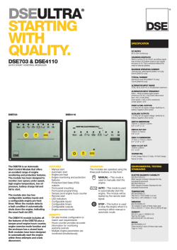
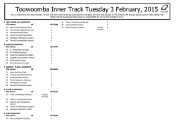
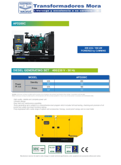
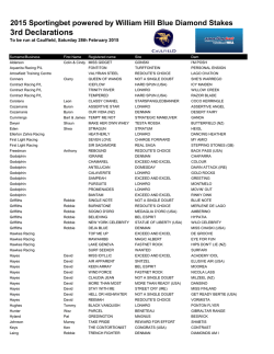
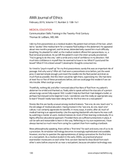
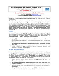
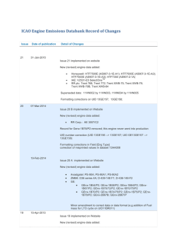
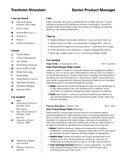
(ARDWAREINTHE,OOP4ESTING
IN2ACING!PPLICATIONS
0ETER7AELTERMANN4HOMAS-ICHALSKY*OHANNES(ELD
D30!#%'MB(0ADERBORN'ERMANY
0UBLISHEDAT3!%-OTOR3PORTS%NGINEERING#ONFERENCE%XHIBITION
$EARBORN
.O2004-01-3502
D30!#%
2004-01-3502
Hardware-in-the-Loop Testing in Racing Applications
Peter Waeltermann, Thomas Michalsky, Johannes Held
dSPACE GmbH, Paderborn, Germany
Copyright © 2004 SAE International
ABSTRACT
Hardware-in-the-loop (HIL) simulation has established
itself as a standard method of testing electronics
components in the automotive industry. HIL simulators
are now being used both by automotive suppliers and by
automobile manufacturers. In racing particularly, the high
cost of the vehicles and test benches means that
frequent virtual test drives and tests are run on a
simulator. The objectives are to ensure the greatest
possible hardware and software quality before going over
to the test vehicle or test bench, to cut costs, and to
minimize the danger to test drivers.
Virtually all major formula 1 teams and some rally teams
(WRC) use dSPACE simulators as HIL electronics test
systems, for example, for the widely used electronics
platform from Magneti Marelli and also for their in-house
developments. The major focus is on ECU testing but
aspects of ECU calibration will also be discussed. The
paper describes this technology and presents solutions
prepared for racing teams worldwide.
INTRODUCTION
Hardware-in-the-loop (HIL) simulation has become a
standard method of testing electronics components in
the automotive industry. HIL simulators are now being
used by both automotive suppliers (for component tests)
and automobile manufacturers (for network and
integration tests).
In racing particularly, the high cost of the vehicles and
test benches means that frequent virtual test drives and
tests are run on a simulator. The objectives are to
ensure the greatest possible hardware and software
quality before going over to the test vehicle or test bench,
to cut costs, and to minimize the danger to test drivers.
This paper presents applied hardware-in-the-loop
simulation with reference to the particular requirements
of motorsports (especially Formula One) and describes
relevant customer solutions.
HARDWARE-IN-THE-LOOP-SIMULATION
In hardware-in-the-loop simulation, one or more real
components (for example, electronic control units) are
studied in interaction with components simulated in real
time (models, for example, of the engine, transmission,
powertrain and whole vehicle).
The interactions between real and simulated subsystems
make tough real-time demands on these systems. High
computing power (processor hardware for simulating the
models, and the actuators and sensors) and I/O
performance are therefore essential preconditions.
Frequently, special hardware is used, for items such as
fast engine signals and for generating and measuring
CAN signals.
Using HIL simulation has the following advantages:
•
•
•
Figure 1: Virtual test drive with HIL simulation
•
•
The hardware and software of electronic control
units (ECUs) can be tested (automatically) at an
early stage because there is no need for a real
engine or a real transmission to be present resulting in greater maturity before transfer to the
test bench or vehicle.
Fewer test drives and test bench experiments
are needed, and also fewer vehicle prototypes or
vehicle components - resulting in cost savings.
Safety-critical components (such as drive-bywire) can be tested without danger. Component
failures and associated emergency scenarios
can be tested reproducibly.
Difficult ambient conditions (winter tests, rain,
high or low temperatures) can be achieved by
simple parameter changes.
Test bench experiments are highly reproducible.
•
The vehicle and its components can be
visualized by 3-D animation. This functionality
can be extended, right through to a real drive
simulator for man-in-the-loop applications.
HIL simulation has established itself as a standard in the
development process for passenger and sport-utility
vehicles and is also growing in importance in
motorsports.
MOTORSPORTS REQUIREMENTS
Clearly, many of the above advantages also apply to
motorsports. Compared with the development of
production vehicles, however, motorsports have their
own specific and even tougher requirements:
•
•
•
Test drives are several times as expensive in
motorsports as for production vehicles, and
moreover, they are partially restricted to only a
few weeks a year (F1).
When test drives are performed, all the relevant
data has to be logged via the central electronics,
as most racing cars cannot take additional
measuring equipment on board. Moreover, it is
not possible to sit in the passenger seat and
modify ECU variables via a calibration system to
fine-tune the system. This is only possible via
telemetrics, if at all.
Software development is characterized by
weekly software releases and last-minute
modifications (short iteration loops). The ECU
parameters are individually adjusted for each
racetrack.
REQUIREMENTS
SIMULATION:
WITH
REGARD
TO
HIL
HIL simulation requires enormous processing power for
the real-time simulation of the engine, powertrain, and
vehicle dynamics components. Because of the
dynamicity of the components and the high engine
speeds, simulation step sizes of approx. 50 – 250 us are
usually used, as compared with production vehicle
applications, where 500 us – 1 ms are more usual.
-1
And engine speeds of up to 20,000 min , anglesynchronous generation of crankshaft and camshaft
signals, and angle-synchronous capture of injection and
ignition signals, require extremely fast I/O subsystems.
Special hardware is generally used for this.
In motorsports, vehicles frequently have special sensors
(LVDTs, thermocouples, linear lambda probes, etc.) and
actuators (Moog valves, fast injection and ignition
systems [1] that have only very limited use in production
systems for cost reasons (for example, LVDTs for
automated transmission). Mapping these for HIL
simulation thus often requires special hardware or
software solutions.
In contrast to production vehicles, the CAN busses in
racing cars are always run at the highest baud rate
(1Mbit/s). Typical tasks include capturing all the CAN
messages of the ECU network and CAN restbus
simulation for emulating absent network nodes. This is
particularly important if the chassis and the engine are
not developed on the same site (as is the case with most
F1 teams).
TYPICAL ECU ARCHITECTURES AND DETAILS
The functionality of sensor systems in motorsports is
hardly any different from that in production vehicles.
However, there is a considerably greater volume of
physical variables such as temperature, pressure, and
air/fuel ratio to be captured. Racing cars generally have
far more sensors (> 100). The sensors used are
optimized for racing purposes (weight, dynamics,
precision) and are often specially produced custom
components.
Figure 2: Typical sensors and actuators for racing
applications
As vehicle electronics are increasingly decentralized, the
ECU network is spread across almost the whole vehicle.
With this decentralized structure, the number and weight
of cable harnesses can be reduced. Fig. 3 shows a
typical decentralized F1 vehicle topology with a few
selected components.
Figure 3: Typical decentralized F1 vehicle topology
with selected components
Figure 4: Components of a hardware-in-the loop test system for racing
dSPACE SIMULATOR TECHNOLOGY
Virtually all major F1 teams (e.g., Ferrari, Toyota [2]) and
some rally teams (WRC) use simulators from dSPACE in
Paderborn, Germany, for HIL electronic testing, for
example, for the widely used electronics platform from
Magneti Marelli (Step9, Step10, from 2005 also Step11),
from TAG McLaren, and also for their in-house
developments.
The simulators are used on the one hand for testing
components, for example, the engine electronics
subsystem. On the other hand, the entire system
including all the essential elements of the ECU network
is tested. The simulator has to be able to cope with the
resulting complexity of the ECU network, and its
hardware and software need to be scalable.
OVERVIEW: THE COMPONENTS OF A SIMULATOR
Fig. 4 shows the typical subcomponents of an HIL
simulator and their interactions. Other important
hardware components apart from the ECUs are the
processor and I/O hardware, the signal conditioning, and
the electrical failure simulation. On the software side, a
graphical user interface (incl. animation environment)
and dynamic models of the vehicle components are
required. A test automation environment is also needed
to automate test sequences. These components are
described in detail in the following chapters.
HARDWARE
The core element is the generic real-time hardware,
which comprises the processor board and I/O boards
tailored to the actual application. The simulation
requirements for testing the ECU and ECU’s networks
are therefore addressed by the solutions described
below.
Processor Hardware
Dynamic models of the engine, transmission, powertrain,
and vehicle dynamics are executed on a real-time
processor hardware, such as the dSPACE DS1006
Processor Board at sampling rates of 50 us to 1 ms. The
board has an AMD Opteron® processor with a clock rate
of 2.2 GHz, allowing it to compute a mean-value engine
model, a brake hydraulics model, and a vehicle
dynamics model, including the entire I/O for the engine
and vehicle dynamics control, in less than 350 us. For
even more complex models, or to connect several
simulators, the boards can be networked to form
distributed multiprocessor systems.
I/O Hardware
Electrical Failure Simulation
The I/O capability of the simulators is directly derived
from the actual application. Engine simulation, for
instance, involves generating crankshaft, camshaft and
knock signals synchronously to the engine angle, while
injection
and
ignition
signals
are
measured
synchronously to the crank angle. Special hardware is
generally used for this task, for example, the DS2211
HIL I/O Board, which is in widespread use in the
automotive industry, for passenger cars and trucks as
well as racing applications. The board provides the entire
I/O for an 8-cylinder engine including signal conditioning,
for example, and is cascadable to accommodate F1
10-cylinder engines either. Thanks to its modularity,
further I/O boards can be added, covering all analog,
digital and resistor channels. Regarding CAN nodes, the
simulator hardware can provide as many CAN controllers
as required.
As a rule, all manufacturers of racing ECUs specify
electrically protected ECU pins, but the racing teams still
perform validation against this specification. Electrical
failure simulation is an integral component of the
simulator, and allows actions such as switching ECU
pins against VBAT or ground and interrupting lines.
Mechanical set-up
The mechanical simulator setup follows a generic
approach, thus having a standard rack encompassing
the individual components. Among others, the cabinet
comprises real-time hardware, signal conditioning, failure
simulation boards, load cards, break-out-boxes (BOB),
etc.
SOFTWARE
The software for the test systems basically consists of
two components, the software for model and I/O
definition and the user control software for the test
system.
Software for Model and I/O Definition
With the dSPACE test systems, modeling and I/O
®
®
specification are based on MATLAB /Simulink , the
quasi standard for describing dynamic systems in block
form. For defining the dynamic behavior of engine,
transmission, and vehicle dynamics, Simulink and
®
Stateflow have established their market position.
Extensive Simulink block libraries are available for
defining I/O in the same Simulink environment.
dSPACE’s Real-Time Interface (RTI) is a Simulink block
library that not only allows analog and digital inputs and
outputs to be specified in Simulink. It also contains easyto-use blocks for the most complex situations (see
Fig.6).
Figure 5: General structure of a dSPACE Simulator
Full-Size
Signal Conditioning
Although the signal conditioning needed for many
automobile-specific signals is provided by the DS2211
HIL I/O Board mentioned above, some signals still
require special signal preparation, for example, for
broadband
lambda
probes,
LVDT
sensors,
thermocouples, etc.
Figure 6: Simulink block library for I/O signal
specification
One example is the angular processing unit (APU) of the
DS2211 HIL I/O Board. This intelligent I/O subsystem
performs all crankshaft angle based functions. The APU
receives the current engine speed from the real-time
simulation and integrates it with the current crankshaft
angle, at an update rate of 4 MHz and a precision of
0.01°. Digital or analog crankshaft and camshaft signals,
and knock signals, are then generated at the same
precision. Angle-synchronous capture of injection and
ignition signals (incl. multiple injection and ignition) is
based on the APU, with the stated time and angle
resolution.
Figure 7: Crankshaft and Camshaft signal of a typical
racing application (MATLAB® plot)
Although these hardware-related functions are
processed on an FPGA, the ignition sequence, and the
crankshaft and camshaft signals, are completely
specified in Simulink, by means of wave tables (MAT
files).
The signals can either be generated synthetically (e.g.,
sinus function for variable reluctance sensors) or come
from actual measurement. It is also possible to switch
between different wave tables at run time, for example,
to simulate a faulty toothed wheel. With analog sensors,
the amplitude of the signal can also be adjusted to
engine speed behavior (Uamplitude = f(rpm)). This is
particularly important for racing systems from Magneti
Marelli.
For defining CAN messages to read from or write to the
CAN bus, RTI also provides block libraries that allow
CAN data (DBC format) to be read in so that messages
from the test system can be coded and decoded with the
correct signal scaling.
In addition to the component models, ECU models are
also frequently implemented (“soft ECUs”) or are already
available from function development. The soft ECUs are
used in offline simulation or if real ECU prototypes are
not yet available. Central switches in the I/O model can
be used to switch back and forth between the simulated
and the real ECU. The soft ECUs can also be employed
for dynamic CAN restbus simulation, making it possible
to mix real and simulated CAN network nodes, for
example, if not all CAN nodes are available in real form.
As already mentioned, because of the high clock rates
and associated processing power requirement,
multiprocessor (MP) systems are often used. Here too, it
is important to specify the entire MP system, including
interprocessor communication, from one Simulink model.
RTI blocks with appropriate sensor and actuator scaling,
and dynamic model behavior, therefore allow seamless
®
®
specification based on one MATLAB /Simulink model.
®
The MATLAB Real-Time-Workshop (RTW) is then used
to generate the C code for the real-time hardware from
this model. Thus, it is generally not necessary to have a
knowledge of C programming to generate the simulator
code.
Figure 8: Graphical User Interface based on ControlDesk Layouts [2]
Interactive Operation
The ControlDesk program is used for interactive
operation of the test system. ControlDesk allows users to
generate convenient, graphical user interfaces (layouts)
with a great variety of control elements, from simple GUI
elements (push-buttons, displays, radio buttons, etc.) to
complex plotters and photorealistic graphics. Fig. 8
shows examples of application-specific layouts.
In addition, ControlDesk is used to control the simulation
and electrical failure simulation, and to manage
interactive experiments. A macro recorder and
programmable switch elements for convenient
maneuvering between layouts round off the functionality.
Apart from this interactive work on the simulator using
ControlDesk, other important aspects of working with the
HIL test system are automated testing and (for vehicle
dynamics particularly) the animation of motion data.
Real-Time Models
To map the real world in the simulator, real-time models
for all the relevant vehicle components are implemented.
For example, the engine, transmission, powertrain, and
engine dynamics (incl. wheels) are modeled and then
computed on the real-time hardware. The models are
generally provided by the simulator customers, but
sometimes commercial models are integrated, such as
ve-DYNA/en-DYNA [3] from TESIS, Munich, Germany,
and CarSim [4] from MSC (Mechanical Simulation
Corporation), Ann Arbor, MI, USA.
The dynamics of the engine, transmission and
powertrain must be represented precisely in order to test
dynamic control behavior. For example, if the gearshift
strategy needs to be checked or optimized, the following
items are investigated:
•
•
•
•
•
•
Environment model (track, ground surface,
irregularities, etc.)
Vehicle model, incl. aerodynamics (ground
effect) to determine wheel forces
Tire model (to compute slip)
Powertrain model (for torque distribution in the
differential)
Transmission model (gearshift dynamics and
clutch)
Engine model (engine torque and speed
computed from injection and ignition during
gearshift)
These are all tested in interaction with the real ECUs.
When one considers that the entire gearshift operation
usually takes only between 20 ms and 40 ms, it is
obvious that the quality of both the model and the
simulator hardware has to fulfill very tough requirements.
There are generally two approaches to engine models:
a) Extended mean value models in which the whole
dynamic engine process is regarded as a
continuous energy flow [5] Sampling rates of 250
– 500 us are usually sufficient to simulate
Formula One engines with this approach.
b) Models based on the Vibé curve, in which each
cylinder-selective combustion process (engine
torque behavior) is described separately and
computed on the basis of individual injection and
ignition signals, and of the intake manifold
pressures. For common Formula One engine
speed sampling rates, between 50 and 100 us
are needed to describe the engine torque
behavior precise enough for ECU testing.
Test Motivation in Racing
The requirements for the test scenario are in large part
the same in racing as for testing production vehicle
ECUs. However, there are some specific aspects to be
taken into consideration.
Component Testing
The ECU software is constantly being further developed
and modified. There are new releases every week, and
these have to be tested before they can be put in the
racing vehicle. Component testing also includes tests on
submodules of an ECU network before they are
integrated into the overall system.
Network Testing
Network tests are derived directly from the component
tests. Sufficient validation is required that the individual
ECU network components add up to a functioning overall
system, i.e., whether communication is via CAN busses
or ArcNet functions.
Regression Testing
Any time one element in the ECU network is modified, all
functions have to be tested again to ensure that
complete functionality has been preserved.
Limp Home Testing
The ECUs must guarantee that even if sensors and
actuators fail, the overall system will still go on working.
Suitable limp-home strategies allow the racing car to
continue moving, as much as possible, despite functional
faults. And before safety-relevant functions can be
integrated into the vehicle, the possibility of function
failure has to be excluded under all circumstances. This
type of test includes investigating whether drive-by-wire
systems react to the failure of specific sensors (e.g., the
throttle valve sensor) in the manner expected.
Test Automation
Further development of the extremely complex ECU
functionality, and very short times between releases,
make it essential to automate tests. Automation also
makes it easy to implement 24/7 operation, which can
dramatically shorten development times. The racing
teams implement tests in different ways. The following
methods are used (Fig. 9):
ControlDesk Stimulus Editor
Graphical description of the test sequence using the
signal patterns, that determine, for example, the behavior
of a sensor. The Stimulus Editor provides access to
models of all sizes. It is also possible to specify the
control flow (e.g., If-Then-Else) within the test sequence.
Textual Description
An integrated script language is used to describe the test
procedure.
Test Description in Simulink
The test sequences are implemented in the Simulink
model. Items such as an ECU input are stimulated by a
test signal via standard Simulink blocks.
AutomationDesk
Tests must be systematically automated, appropriately
structured, and reused, in order to achieve the targets
regarding test depth and test width, and therefore also
quality. In the recent past, test automation applications
were frequently developed in programming languages
and were customer-specific. Unlike previous solutions,
AutomationDesk allows tests to be constructed in
graphical form, without knowledge in programming.
Further advantages include integrated test management,
a powerful mechanism for creating custom test libraries,
result management and integrated report generation
(Fig. 10).
Figure 9: Different approaches to defining ECU tests:
a) ControlDesk Stimulus Editor,
b) Scripting, c) Test definition in the model
Figure 10: AutomationDesk, an integrated environment for automated testing [6]
APPLICATIONS
SYSTEM DESIGN IN RACING
There is no such thing as “the” standard racing
simulator. For component testing, the functional scope of
the simulator, and therefore also the I/O capacity, can
be much smaller. For example, a component testing
system (Fig. 11) can do without items such as ignition
and injection channels if tests are to be performed on the
transmission or powertrain.
Simulators for motorsports are precisely tailored to the
ECUs to be tested. Their size depends on factors such
as the following:
•
•
•
•
•
The number of ECU pins
Whether an ECU network is involved (e.g.,
Magneti Marelli Step10/11, McLaren MCU
300/TAG-300) or a single ECU (e.g., Magneti
Marelli Step9)
How many additional components have to be
integrated into the overall setup
The scope of the tests (component tests, system
tests, etc.)
The processing requirement of the model, i.e.,
whether a multiprocessor system is needed
Figure 11: Simulator for ECU component testing
Figure 12: Laboratory setup of the hardware-in-the-loop system [2, 7]
SENSORS AND ACTUATORS
The sensors and actuators are implemented in off-theshelf signal conditioning modules for racing simulators
The simulator hardware is precisely tailored to the
scaling in the Simulink model. In contrast to productionvehicle components, sensor characteristics in racing
applications are captured individually. The I/O model is
parameterized via a start-up script. The racing teams
generate the major part of the Simulink model
automatically, so that they can perform actions such as
integrating new sensors into the simulation in a matter of
seconds.
Thermocouples
Thermocouples have a very low output voltage, which is
provided with great precision by a special mV module.
The control range, e.g., 0 - 50mV, is specified in the
model.
MODEL STRUCTURE
To fulfill motorsports requirements with regard to
processing
time,
the
simulators
are
mainly
multiprocessor systems. Typically, the model is split into
the I/O part and the dynamic model, each of which has
its own processor board.
These are examples of components installed in
motorsports simulators (by analogy to the components
described in chapter dSPACE Simulator Technology):
Linear Lambda Probe
Broadband lambda probes are mostly used in
motorsports to operate the racing engines at optimum
performance (lambda appr. 0.9). The simulator is
equipped with a lambda probe module that sets the
pump current according to the lambda value provided by
the model and if necessary also varies the internal
resistance of the Nernst cell with reference to the
exhaust
temperature.
The
characteristics
are
parameterized directly in Simulink, for example, by
inserting the 1-D look-up Ip=f(lambda). In an ideal case,
the manufacturer’s specification or the developers’ own
measurement series can be transferred to the model for
this.
LVDT Sensor
To detect the positions of the clutch or to capture the
brake disk wear, racing vehicle developers frequently
use (linear variable differential transformer (LVDT)
sensors. To simulate the sensor, the LVDT module in the
simulator reads the excitation signal (primary side) and
makes the output signal (one or two secondary coils)
available to the ECU in the correct phases. The
deflection is placed directly in the model as the function
UDAC = f(s).
Active Wheel Speed Sensor
Active wheel speed sensors generally have a current
interface whose level is provided by the simulator. The
frequency to be output is scaled in Simulink according to
the sensor data (teeth/wheel circumference) and
converted, for example into a 7/14 mA level.
Moog Valves
The current-controlled Moog valves are read in indirectly
via voltage measurement at a shunt. In the model, the
voltage is converted into control current, which in turn is
the input for the dynamic Moog model. Usually, the
effective deflection of the actuator is computed via the
integration of the coil current (which corresponds to a
specific control speed). Here too, the transfer behavior
from coil current to control speed is included in the model
as a look-up table.
Figure 13: Simulink model structure for a multiprocessor system incl. interprocessor
communication
IGNITION AND INJECTION
The DS2211 always provides angle-based ignition and
injection pulse capture and flags the absence of pulses.
It is extremely important to ensure that any cut-off is
detected, because when the ECU cuts off the ignition or
injection, the associated status information must be
generated as soon as possible in the simulator. The
pulse status for each cylinder is then used within the
model, to reflect the torque drop. When there is no pulse,
the DS2211 generates a pulse state of 0. Typically this
information is included in the computation of the engine
torque. (Fig. 14)
Figure 14: The torque computation must take
ignition cut-off into account
The resolution of the engine variables depends directly
on the sampling rate at which the Simulink model is
computed. For the best possible resolution, for example,
of the pressure behavior in the cylinder, the sampling
rate must be as low as possible.
An example: Revolutions of 18000 rpm correspond to a
change speed of the crankshaft angle of 108°/ms or
0.108°/us. If the dynamic model is computed at 1 kHz,
the resolution is only 108°. A crankshaft angle of 21.6°
can be achieved at 5 kHz, and of 5.4° at 20 kHz.
Obviously, the real-time hardware must compute the
model as fast as possible to achieve optimum resolution.
Especially for engine models that compute the
combustion behavior in the cylinder (Vibé curves), model
clock rates of 50 us are desirable (Fig. 15).
REAL-TIME PROFILING
In all cases, the application as implemented must include
the model’s behavior over time. In addition to the
specified sampling rate, the effective computing time
required for each task is also represented. If a violation
of real time is detected, it may be necessary to increase
the sampling rate. The timing is profiled with the help of
ControlDesk, giving access to vital simulation time data
such as sample rate, task turn-around time, task call
counts, task overruns, etc. It is crucial to check the
application’s behavior over time, i.e., how much
headroom actually is available taking into account time
consumption peaks.
Figure 15: ControlDesk Layout showing the effective
computing time in seconds for individual simulator
tasks by means of numeric displays
REAL PARTS
There are many different reasons for integrated real
parts into the simulator. For example, if there are
submodels that are not (or not yet) available in Simulink,
the control loop concerned can still be closed by
including the real part. Some components can be very
difficult to model, so engineers fall back on integrating
the real parts, for example, a real throttle valve, to close
the control loop for simulation.
With racing car components that are controlled by the
driver, such as the steering wheel, pedals, or console
(rally cars), the aim is to make the simulation as realistic
as possible.
Figure 16: Simulator for rally (WRC) applications with original customer components
Junction Boxes
USER INTERFACES
The connections in racing vehicles are generally military
industrial cylindrical connectors (MIL). To connect the
ECU network to the simulator, specific junction boxes
are used. As a rule, the boxes are made by the teams,
and they can be located inside or outside the simulator.
This makes it possible to use the original vehicle cable
harness, or parts of it, in the simulation environment.
Specific ECU functions have their own control layouts, in
addition to the general layouts for system control (such
as voltage supply). For example, different layouts are
available for low-level functionalities such as ignition and
injection and higher-level control functions such as
launch control and traction control.
GATEWAY OPERATION
The simulator is able to corrupt specific signals that are
exchanged between the ECUs and other peripherals in
the vehicle. This method of intervention (gateway) is
based on the principle of the simulator fetching all the
relevant signals, corrupting them in real time, and
outputting them to their recipients. It does not matter
whether the gateway is for discrete signals or for CAN
bus signals.
Figure 18: F1 simulator layout for dynamic model
data analysis
For pure channel stimulation, stimulus layouts are also
used. When a test value has been set in a layout, its
correct implementation in the ECU can immediately be
checked by a calibration tool. Fig. 19 shows a test layout
from a rally application, in which all speed signals can be
specified on one layout. These specifications can of
course also be completely automated.
Figure 17: F1 steering wheel as an example of
gateway operation
For the steering wheel, for example, analog signals from
position sensors are read in on ADC channels. These
signals can then be output again unchanged (correct
behavior), or their values can be corrupted by a test
value on the operator’s PC and then sent to the ECU via
the appropriate analog output port (incorrect behavior).
CAN data are also manipulated on the same principle.
Signals received from both the ECU and the steering
wheel are available as physical values according to CAN
scaling (offset and gain). These values can be corrupted
on the basis of physical units and then put on the bus by
the simulator. Besides changes to individual CAN signals
(such as checksums), entire messages (missing, wrong
timing), and even the complete absence of a bus node
can be simulated and their effect on the rest of the
network investigated (see [8]).
Figure 19: Test layout in a rally application for
stimulating individual channels
AUTOMATED STIMULUS TESTS
The ECU is stimulated by the precise data recorded
during an actual test drive or in test bench trials. Feeding
this data into the simulator brings the ECU to the
operating point near which a function fault, for example,
was detected, making it possible to investigate in detail in
the laboratory.
If a Simulink model of the ECU functionality is available,
function tests that validate the software ECU against the
real hardware can also be automated.
ANIMATION
Animating the vehicle is done with dSPACE MotionDesk;
a tool, which provides 3-D animation of mechanical
system in a virtual world. There are essentially three
steps involved in animation for HIL simulation:
•
•
•
The vehicle must be embedded in a virtual, 3-D
landscape. For motorsports applications, the
animation scene is given items such as a track
definition that corresponds to real racetracks or
the team’s real test track.
When these steps have been completed, the vehicle
dynamics can be analyzed in the virtual 3-D world in
MotionDesk in parallel to the simulation run. As a rule,
real steering wheels are available on the simulator to
allow man-in-the-loop operation, i.e., the user can steer
the simulated vehicle, interacting with the ECU network
while at the same time receiving visual and acoustic
feedback (e.g., by sound generation to mimic the engine
speed).
The motion data of the dynamic vehicle model
(roll/pitch/yaw, translation) must be linked to the
bodies to be animated (chassis, wheels, steering
wheel, etc.) via special Simulink blocks
(MotionDesk library and others) to create
kinematic chains.
Geometries from the CAD systems of racing
teams are very complex and have a large
number of polygons (>50000). These large
polygon counts cannot be handled under realtime conditions on a PC. Thus the original data
formats of these CAD systems must be
transferred to a data format (VRML2) that is
suited to animation.
Figure 21: 3-D visualization of a racing vehicle
Figure 20: Sequence of an automated stimulus test using track data
Electric Drive
Real
Gearbox
Test
Bench
Control
Electric Brake
CAN
Engine
Dyn.
Model
Transm.
Controller
Transm.
Model
Driver/Excitation
Model
Diff.
Controller
(Model)
Veh. Dyn.
Controller
(Model)
Differential
Model
Vehicle
Dynamics
Model
Environment
Model
...
Test Bench Interface
Engine
Controller
(Model)
Real-Time Simulation
= Real
= Real or Virtual
= Virtual
Figure 22: Test bench with real gearbox and transmission controller in combination with a real-time
simulation (HIL) environment
Another example is shown in Fig. 23. Here the engine,
transmission and differential are mounted on the test
bench, while the vehicle dynamics, driver and the
environment are simulated on an HIL system in real time.
As in the first example above, the corresponding torque
and speed signals of the drive shafts are simulated and
applied to the powertrain by means of two electric
brakes.
Test Bench
Real
Differential
CAN
Engine
Controller
Engine
Model
Transm.
Controller
Diff.
Controller
Veh. Dyn.
Controller
(Model)
Transm.
Model
Diff.
Model
Vehicle
Dynamics
Model
Driver/Excitation
Model
Environment
Model
Test
Bench
Control
Electric
Brake
Real
Gearbox
Real Engine
...
Test Bench Interface
In engine and powertrain development for motorsports,
the test benches used are generally highly dynamic and
allow transient processes during an acceleration phase
(incl. gearshifts) and during start-up to be mapped
sufficiently well. The load definitions for such test
benches are based either on recorded track data or on
predefined excitation scenarios, quasi in an open loop.
However, to study the dynamic behavior of the
powertrain, including the engine and the steering
electronics, as they interact with the environment, the
highly dynamic test bench has to be connected to the
real-time simulation of the environment.
Some examples of this are optimizing traction control in
F1 and rally vehicles, optimizing the gearshifts (up shift,
down shift), and investigating the interaction between the
engine and the transmission if one of them is not
available. This can be the case, for example, with F1
teams that do not perform development at a single
location, unlike Toyota and Ferrari.
A transmission test bench with a real gearbox and
transmission ECU, a real or simulated engine controller,
and electric motors applying loads to the drive shafts of
the gearbox, is an example of this (Fig. 22). The
behaviors of the engine and the vehicle are simulated in
real time, and the resulting variables, drive shaft torque,
and speed, are introduced via the electric drive and the
electric brake.
Electric
Brake
TEST BENCH INTEGRATION
Real-Time Simulation
= Real
= Real or Virtual
= Virtual
Figure 23: Test bench with real powertrain (engine,
transmission, differential and corresponding controllers) in combination with a real-time simulation
(HIL) environment
The test bench system and real-time simulation can be
connected via CAN bus, Interbus, or Profibus, or via
proprietary interfaces (such as a dSPACE AVL link).
This test bench configuration has the following
advantages:
•
All ECUs can be integrated with real
components at an early stage. This is particularly
important if an ECU is available, but not the
component
to
be
controlled
(engine,
transmission, vehicle).
•
The real testbed component does not need a
dynamic model, nor do the real ECUs.
Tests on the interaction between real and
simulated components are highly reproducible.
Suitable parameter sets for the ECUs can be
generated even before the track test. This
makes it likely that there will be fewer problems
in transferring from the test bench to the
racetrack, and greater software quality is
achieved.
•
•
SUMMARY AND OUTLOOK
This paper discusses the various options for using
hardware-in-the-loop simulation in motorsports. Starting
with the necessary hardware and software components
of modern HIL test benches, concrete motorsports
requirements and implemented solutions are presented.
Finally, the integration of real-time simulation with
concrete drive test benches and the resultant application
scenarios are described. However, due to obligations of
confidentiality, it was largely necessary to avoid detailed
descriptions of concrete customer projects.
In the future, the authors see a clear trend towards a
continued increase in the complexity of software and
hardware systems in racing vehicles, as the basis for
further performance growth in motorsports. The
necessity of increased testing and more complex test
systems will also rise in direct proportion to this. In both
production and motorsports vehicles, determining
variables that cannot be measured via substitute models
in the ECUs will grow in importance. Observer systems
such as those that are already in standard use for slip
detection in vehicle dynamics control systems might also
be used more in motorsports.
As active intervention is subject to tough regulations
(especial in Formula One), the focus is mainly on
existing actuators (especially the engine and
transmission). This is different in rallying, where far more
active intervention is allowed.
Future technical developments in Formula One remain
difficult to predict, as frequent new proposals on the
number of cylinders and displacement, and on the muchdiscussed “standard electronics”, are made by the FIA.
As regards the latter, it is still unclear whether only the
hardware, or the software functions too, or even software
parameterization, are to be standardized. It remains to
be seen which way the discussion will go.
REFERENCES
[1] Wright, P.: Formula 1 Technology; SAE Society of
Automotive Engineers, Warrendale, PA, USA, 2001.
[2] Urban, P.; Wältermann, P.; Henking, B.: Toyota
Motorsport Racing Ahead with dSPACE (In German:
Toyota Motorsport mit dSPACE auf der Überholspur.
Automotive Engineering Partners 6/2001, S. 40.
English Version available via: http://www.dspace.de/
ftp/papers/dspace_AutEP_0111_e_f22.pdf
[3] TESIS DYNAware: enDYNA®, veDYNA®, Product
Description. Munich, Germany, http://www.tesis.de.
[4] Mechanical Simulation Corporation: CarSim®
Product Description. Ann Arbor, Mi, USA,
http://www.carsim.com.
[5] Hendricks, E. / Sorenson, S.: Mean Value Modelling
of Spark Ignition Engines. SAE Paper No. 900616,
Society of Automotive Engineers, Warrendale, PA,
USA, 1990.
[6] Lamberg, K.; Richert, J.; Rasche, R.: A new
Environment for Integrated Development and
Management of ECU Tests. Society of Automotive
Engineers, SAE Paper No. 2003-01-1024.
[7] Urban, P.: Verification of a decentralized ECU
system for a Formula 1 car by means if Hardware-inthe-Loop-Simulation (in German). Conference:
„Hardware-in-the-Loop-Simulation
in
Vehicle
Development“, Haus der Technik, Essen, 2001.
[8] Plöger, M.; Sauer, J.; Büdenbender, M.; Held, J.;
Costanzo, F.; de Manes, M.; di Mare, G.; Ferrara, F.;
Montieri, A.: Testing Networked ECUs in a VirtualCar
Environment. Society of Automotive Engineers, SAE
Paper No. 2004-01-1724.
53!AND#ANADA
D30!#%'MB(
4ECHNOLOGIEPARK
0ADERBORN
4EL &AX INFO DSPACEDE
WWWDSPACEDE
D30!#%)NC
#ABOT$RIVE3UITE
.OVI-)
4EL
&AX
INFO DSPACEINCCOM
WWWDSPACEINCCOM
&RANCE
5NITED+INGDOM
D30!#%3ARL
0ARC"UROSPACE
"ÉTIMENT
2OUTEDELAPLAINEDE'ISY
"IÒVRES#EDEX
4EL &AX INFO DSPACEFR
WWWDSPACEFR
D30!#%,TD
ND&LOOR7ESTMINSTER(OUSE
3PITlRE#LOSE%RMINE"USINESS0ARK
(UNTINGDON
#AMBRIDGESHIRE0%89
4EL &AX INFO DSPACELTDUK
WWWDSPACELTDUK
¢#OPYRIGHTBYD30!#%'MB(!LLRIGHTSRESERVED7RITTENPERMISSIONISREQUIREDFORREPRODUCTIONOFALLORPARTSOFTHISPUBLICATION4HESOURCEMUSTBESTATEDINANYSUCHREPRODUCTION
D30!#%ISCONTINUALLYIMPROVINGITSPRODUCTSANDRESERVESTHERIGHTTOALTERTHESPECIlCATIONSOFTHEPRODUCTSCONTAINEDWITHINTHISPUBLICATIONATANYTIMEWITHOUTNOTICE
"RANDNAMESORPRODUCTNAMESARETRADEMARKSORREGISTEREDTRADEMARKSOFTHEIRRESPECTIVECOMPANIESORORGANIZATIONS
D30!#%
(EADQUARTERSIN'ERMANY
© Copyright 2026