
Catalogue 2013-2014 v1 (ENG)
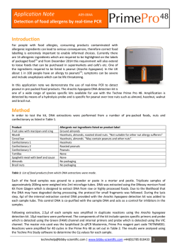
Brochure
2013–2014 v1
Table of Contents
The World of Biotechnomica
2
Reverse–Spin® Technology — Innovative
Principle of Microbial Cultivation
4
Development and evaluation of DNA
amplicon quantification. Case study:
UV–Cabinet with UV Air Recirculator
UVC/T-M-AR and Class II Biological Safety
Cabinets
9
Inactivation of DNA molecules by
physicochemical factors in laminar flow
cabinets (BSC class II)
17
UVR-M and UVR-Mi, UV Air Recirculators
Test Report
25
MCF-48T, Real Time Isothermal
Amplificator Preliminary Report
29
Technology for determining activity of
lactatedehydrogenase in Eppendorf
type tubes through NADH fluorescence
intensity
33
User's Guide: How to Choose a Proper
Shaker, Rocker, Vortex
37
1
“In the act of creation, man steps beyond
himself as a creature and rises above passivity
and the coincidence of his existence into the realm
of freedom and meaning. In this need to transcend
can be found one of the roots not only of love, but
of art, religion and material production ”
— Erich Fromm
The World of Biotechnomica
The concept of development for Biosan
called The World of Biotechnomica. Four planetary systems with satellites — devices revolve
around Terra Innovatica (biomaterial under
research). We have marked out four planets — 4
contemporary diagnostic levels:
1. Terra Genomica — diagnostics at the level
of genes (DNA-analysis, oligonucleotide and
mononucleotide polymorphism — ONP,
SNP);
2. Terra Immunologica — diagnostics at the
level of immunology (detection of polymorphism of antibodies and immune response);
3. Terra Biochemica (metabolomics) — diagnostics of metabolism products and ferment
activity;
4. Terra Cellomica — diagnostics at the
level of cellular morphogenesis (cellular
polymorphism).
The distance from the planet orbitals to Terra
Innovatica corresponds to the time of disease
detection at each level (from one week, as in
the case of DNA-analysis, to several years, when
the changes can be traced at the cellular level).
By virtue of genetic nature of the majority of
diseases of human beings, animals and plants
— further affecting the immune response
(defence reaction) and changes in biochemical
status, and finally cellular morphogenesis as
well — we believe that simultaneous multilevel
diagnostics is reasonable. Since polymorphism
at the level of genes leads to the manifestation
of polymorphism at all higher levels, it results in
the ambiguity (if not more) of any decision made
on the basis of the obtained data. The definition
comprising the polymorphism of norm and
abnormality (disease) is not yet available; hence,
the multidiagnostic technology, though expensive, is the only solution as of today.
Although the classic determinism in diagnostics has finally yielded its position to the
stochastic one, there are still no instrumental
solutions allowing to channel our new knowledge into informed and unambiguous decisions.
This is the real situation; these are the temporary
consequences of progress. Biosan is the only
2
Applications and Articles
Vasily Bankovsky, Ph.D. (Biology), Head of R&D Department,
Chairman of the Board at Biosan
company in the World of Biotechnomica, which
develops, produces and distributes instrument
lines for all 4 levels of diagnostics. These satellites
of 4 planets are specialised devices providing
the instrumental basis for multilevel diagnostics,
whereas the reagent sets make these satellites
move. On this account, the term Biotechnomica
in our understanding means the branch of
biotechnology responsible for the development
of multilevel laboratory diagnostics sets (instrument lines). In the future perspective, multidiagnostic chips may appear with the development
of chip technologies, allowing to unify all the
aforesaid technologies in one chip. Biosan plans
to be active in this field in the next few years.
I am pleased to point out that many of
our ideas and products have been developed
as a result of long-standing cooperation of
scientists from the Institute of Microbiology
of the Latvian Academy of Science (where our
company was founded 15 years ago and where
it is presently located) with universities, as well
as with academic institutes and institutes of
applied sciences and our company customers
worldwide.
All our inventions resulted from joint efforts,
and today we are still open for collaboration.
We will be delighted if the result of our work —
which has already received wide recognition of
the Western scientific community — would be
also of interest for you, particularly if it would
serve as yet another starting point for the development of innovative biotechnologies and
appearance of new planets and their satellites in
the sky of the World of Biotechnomica.
Sincerely,
Vasily Bankovsky, Ph.D. (Biology)
Head of R&D Department
Biosan, Chairman of the Board
Te r ra Ce l l o
m
ic
Medical–Biological
Research & Technologies
a
a
Te r r B i o c h e
mi
ca
r
Te r
a Immun
o
lo
gic
a
The
of World
Biotechnomica
Te r ra G e
n
om
ica
rr
Te
a I nn o v at i
ca
3
Reverse–Spin® Technology —
Innovative Principle of Microbial Cultivation
Medical–Biological
Research & Technologies
Data Logging
and Analysis
Authors
V. Bankovsky, I. Bankovsky, P. Bankovsky, J. Isakova,
I. Djackova, A. Sharipo, J. Eskin, A. Dišlers,
R. Rozenstein, V. Saricev, S. Djacenko, V. Makarenko,
U. Balodis.
This paper presents theoretical and experimental studies of the microorganism growth
using Reverse–Spin Technology (RST). Reverse–
Spinner — is a thermostating device with very low
energy consumption that realizes innovative type
of mixing, where liquid (cells in liquid medium) is
mixed by the tube rotation around its axis, leading
to highly efficient Vortex Type Mixing (VTM).
Present work is the first to show experimental
results of cell growth kinetics obtained by using
disposable falcon tubes agitated on a principle of
RST. Growth conditions for several model microorganisms (facultative anaerobe E.coli BL21, extreme
aerobic microorganism Thermophillus sp., and
anaerobic bacteria Lactobacillus acidophilus) have
been optimized. Scientific and applied valuable
aspects of single–used tube RS–Reactors and their
potential niche in different biotechnological fields
are discussed.
RTS-1 — 4 Instruments in 1
Measuring
Mixing
Thermostating
The principles of mixing solutions are among
one of the key fields in Bioengineering science.
Area of mixing is not limited to bioreactors — Table 1, Comparison of Non invasive mixing methods
mixing is also essential in the study of biochemical
#
Icon
Motion
Instrument
Max. V
and molecular biological processes. Non invasive
mixing technology includes a different way of
tubes agitation as shown in the table 1.
1
Absence of agitators inside the reactor gives
opportunities to use Reverse Spinner as a rotating
spectrophotometer (spectra–cells), which measures optical density in the reactor in Real–Time.
Software makes it possible to set optimal
parameters of fermentation, registers and logs all
parameters (mixing intensity, temperature of the
process, optical density and cell concentration,
speed of the growth, etc.).
4
Applications and Articles
Orbital
0.1–5 l
Rocking
1–100 l
3
Overhead
Rotation
1–50 ml
4
Reciprocal
(Hand-type)
1–50 ml
5
Vortex
1–50 ml
6
Reverse
Spinning
2
α°
1–2000 ml
Initiation of the Vortex Type Mixing (VTM)
and depth of the Vortex cave depend on 1)
angular speed of RS–Reactor 2) time from initiating rotation of RS–Reactor 3) growth media
viscosity 4) temperature. These parameters,
also, determine the angular speed of rotating
Vortex Layer (VL) and transition state from
the Irrotational Vortex (IRV), when angular
speed of the VL is proportional to the radius,
to the Rotational Vortex, when the angular
speed of the VL is the same and VL looks like
a monolithic Vortex cavity. Common rules
regulating Vortex type mixing processes may
be stated as follows: the more time has passed
since Vortex formation, the more obvious is a
transition from IRV to the RV. The concept of
the Reverse–Spin mixing is based on these
assumptions.
Noninvasive Vortex Mixing Principle
Spread of the broth media inside of rotation tube
as a function of rotation intensity
Vortex Cave
Broth media
250 min-1
Rotation
around axis
1,000 min-1 2,000 min-1
Rotation Intensity
Reverse Spinning vs Orbital Shaking
Symmetrical vs Asymmetrical broth media distribution
Reverse Spinning
Orbital Shaking
Features:
Features:
•
•
•
•
•
Fits any diameter of the rotating vessel
Natural centric auto–balancing
Simplicity
No power consumption for contra–balancing
Self cleaning optical cells
• Proportionality between orbital diameter and the
diameter of the moving vessel
• Artificial hula–hoop auto–balancing
• Complexity
• Extra power consumption for contra-balancing
Fig 1. Aeration effect on E.coli BL21 growth using different growth techniques
λ=850 nm
λ=565 nm
O2
+O2
–O2
Orbit
Applications and Articles
5
The fig. 1 shows a comparative data of the
biomass yield obtained for the E.coli night culture
cultivated in LB medium in Erlenmeyer flasks
(Shaker–Incubator ES-20, BioSan) and in testtube reactors, RTS-1. Biomass yield is presented
in the optical densities measured at 600 nm and
850 nm wavelengths. The results obtained for a tube
rotating around its own axis at a speed up to 2,000
revolutions per minute.
The experimental data suggests that biomass
yield obtained using the Reverse Spin Technology
is not lower than biomass amount obtained by
traditional methods of cultivation and, as is the case
of cultivation in Erlenmeyer flasks, depends on the
volume of medium in the flask, all other parameters
being equal.
Next, we concentrated our efforts on the development of correct cell concentration measurement
technology in Real–Time. As you may know, the final
concentrations of E. coli cells in LB medium significantly exceed OD=1.0 at λ=600 nm, which requires
stopping the process of growing cells, sterile
sampling and dilution. This makes the process of
growing cells and controlling their concentration
very difficult to reproduce. The problem lies in the
fact that the turbidimetric coefficients unlike molar
extinction coefficients — are not linear. The behav-
iour of light in dense cell suspensions (see fig. 5) is
very interesting and at more than 2 OD at 600 nm it
is almost impossible to measure the concentration
of cells directly (unless you measure the Rayleigh
scattering).
We approached this problem from a different
side. It is known that the shorter the optical path
is, the more accurately it is possible to measure the
concentration of cells, even at high densities (up
to 10 OD). For this purpose, test tubes containing
different volumes of medium are intensely rotated
(2,000 min-1) and as a result, a monolayer of medium
is generated, which thickness is directly proportional to the volume of culture medium in the tube
(see fig. 2 below). Previously, we achieved linearity
in the data, when measuring cell concentrations
from 1–10 OD in the optical path of 1 mm, therefore correction coefficients were introduced in the
program of RTS-1, which allows to measure concentrations of cells in a wide range. The algorithm for
determining the concentration of bacterial cells in
Real–Time includes the formation of the monolayer
at given intervals and cell concentration measuring
process. The process takes 5–10 seconds and then
initially set parameters for the cell growth automatically restore. The graph shows that the cell concentration range optimal for measurement is 5–30 ml of
culture medium in the reactor.
Fig 2. The effect of Media Volume on it's Layer Thickness (mm) during Reverse-Spin cycle
5 ml
10 ml
15 ml
0.55 mm
1.10 mm
1.65 mm
30
25
20
15
10
20 ml
25 ml
30 ml
2.20 mm
2.75 mm
3.3 mm
#
6
V, ml
5
RTS-1, ODonline RTS-1, Layer RTS-1, Optical S-22, ODoff-line 850nm, S-22, ODoff-line 600nm,
850nm
Thickness,
Path, mm 1mm cuvette
1mm cuvette
mm
Cells
Yield,
600 nm
1
5
2.45
0.55
1.10
2.35
5.17
25.8
2
10
1.92
1.10
2.20
2.05
4.51
45.1
3
15
1.71
1.65
3.30
1.92
4.22
63.3
4
20
1.62
2.20
4.40
1.75
3.85
77.0
5
25
1.65
2.25
5.50
1.75
3.85
96.2
6
30
1.45
3.30
6.60
1.50
3.30
99.0
Applications and Articles
Fig 3. Influence of Frequency of Reverse Spinning on the
Growth kinetics and Growth Rate (ΔOD(λ=850nm)/Δt) vs
Time of fermentation (hrs).
Legend of experiment: Real Time Cell Growth Logger was
used — RTS-1 with 850 nm LED, Volume of LB media in 50
ml Falcon = 15 ml approx., Reverse Spin Frequency (RSF) 1, 2,
4, 8, 16, 30 sec -1 , Measurements frequency (MF) is 10 min-1
approx., Rotation speed of reactor = 2,000 rpm , temperature
37°C , Diameter of filters` pores (for aeration) = 0.25 μm .
Fig 4. Influence of Frequency of Reverse Spinning on the
Growth Kinetics vs Time of fermentation of E.coli BL21 in a 3D
model.
Results obtained indicate that the maximum
rate of cell division is detected at a frequency of
1 Reverse Spin per second (1 sec-1) at a speed of
2,000 rpm. The increase of pause between reverse
spins reduces cell growth rate, reaching 50% of the
maximum value, when RS freq. = 30 sec (see fig 3.).
For a better visual representation of the results,
the data of three factor interdependence experiments are presented in the form of the 3D graph
(see fig. 4). Display of the experimental results in
the 3D format has one more advantage that the
obtained data provides a clear visual tool for the
analysis of the complex interrelated processes of
cell growth and allows to find the optimal and
reproducible parameters obtained for the output of
the cell material.
Growth rate versus time data, presented in the
graph, was obtained during 20 hours long fermentation process and optical density was measured in
a 10 minutes interval. The optical density was determined in the monolayer of growing cells and growth
media formed as a result of a Vortex (as described in
the legend to fig. 3). Volume of the culture medium
is taken into account when calculating the length
of the optical path of the rotating tube that allows
to calculate the optical density in standard values
familiar for biotechnologists (λ=600 nm, optical
path: 10 mm).
Classical 2D data view of cell growth versus time
obtained at the endpoint or during cell growth
when cell density was measured at intervals of 1–4
hours do not provide such opportunity.
Applications and Articles
7
The Things to Think About: Behaviour of Light in the Environment of Different Densities
Fig 5. Experiment of Behaviour of Light in the Environment of Different Densities was carried out. Green (535 nm) laser was
used in the Saccharomyces Cerevisiae of different optical densities (OD) in the range from 1 to 10 with 1 OD increment.
5 OD
Light Source
Light Source
9 OD
Light Source
8 OD
Light Source
7 OD
6 OD
Light Source
Light Source
4 OD
Light Source
3 OD
Light Source
2 OD
Light Source
1 OD
Light Source
10 OD
Conclusion
RTS-1 — Reverse Tube Spin cultivation based
on the new method of external agitation of cultivation media, has been shown to be efficient for
cultivation of aerobic microorganisms and cell
growth logging.
Effective growth of E. coli on LB media has
been demonstrated under extremely high speed
rotation of the reactor (2,000 rpm).
To increase an OD measurement range we
investigate near infrared (IR) spectra and showed
that a 850 nm wavelength is sufficient to measure
increased cell concentrations. Such wavelength
shift (from traditional 600 nm to 850 nm) strongly
8
Applications and Articles
expanded a range of correct OD measurements.
Moreover, we propose a new technology of a
non-contact high biomass measurements during
fermentation based on a formation of a thin layer of
cultivation media, giving a correct data of bacteria
concentration in a rotating reactor.
As a result, proposed RTS-1 technology excludes
sampling and dilution procedure that is especially
dangerous for harmful bacteria, pathogens or microorganisms living in extreme conditions, like Thermophilus. Results will be published in next issue of
BioSan Analytica Journal.
Development and evaluation
of DNA amplicon quantification.
Case study: UV–Cabinet with UV Air Recirculator
UVC/T-M-AR and Class II Biological Safety Cabinets
Medical–Biological
Research & Technologies
Authors
Biotechnomica: Marina Tarvida, Julija Isakova,
Vasily Bankovsky
Biosan: Arturs Kigitovics, Vadim Gimelfarb
Introduction
Personal and product safety during clinical and
laboratory studies have stimulated the development of sterile cabinets and special laboratory
safety techniques, to protect the environment,
operator, and product. Monitoring DNA/RNA
amplicon concentration in laboratory air in sterile
cabinets has become topical as PCR and isothermal
amplification technologies have developed along
with wide spread mass analyses.
Development of methods for repeatable
DNA/RNA amplicon detection in air samples is now
a reality. Recent research “Behaviour of aerosol
particles in fibrous structures” (Igor Agranovsky’s
PhD thesis, 2008, Novosibirsk, Russia) describes the
development of samplers and monitoring of DNA/
RNA amplicon concentration in the air from sterile
cabinets, microbial quantitative analyses.
UVC/T-M-AR, UV–Cabinet for PCR operations
DN
am A/RN
plic A
ons
25 cm
50 cm
ses
Distance to UV source, cm
2 cm
Vir
u
50
ter
ia
2
Bac
25
t
2
4
Yea
s
20
i
Distance,
cm
Fun
g
UV intensity,
mW/cm2/sec
UV intensity needed for decontaminating,
mW/cm2/sec
UV intensity, mW/cm2/sec
Fig. 1, Germicidal, shortwave (254 nm) ultraviolet energy is
used for complete destruction of various biological agents
Applications and Articles
9
Aim of the study
Air flow organization through HEPA
filter
The aim of this study is to evaluate the of
efficiency of UV cabinets produced by BioSan
(Latvia) in comparison to Class II BioSafety
cabinets.
HEPA is an acronym for “high efficiency particulate absorbing” or “high efficiency particulate
arrestance” or, as officially defined by the Department of Energy (DOE) “high efficiency particulate
air”.
UV air treatment
More than a century has passed since the
germicidal effect of UV light was recognized by
Niels Ryberg Finsen — a Nobel Prize winner in
physiology or medicine in 1903 [5], and many
researches have been performed on UV induced
destruction of DNA and microorganisms.
The first HEPA filters were developed in the
1940’s by the USA Atomic Energy Commission to
fulfil a an efficient, effective way to filter radioactive particulate contaminants. HEPA filter technology was declassified after World War 2 and
then allowed for commercial and residential use
[6].
Low pressure germicidal UV lamps characteristically emit monochromatic low intensity radiation principally at 253.7 nm, within the germicidal
wavelength range as defined by the DNA absorbance spectrum. The germicidal UV dose LP-UV
lamps is calculated as the product of the volume
averaged incident irradiance (E, mW/cm2) and the
time of exposure (t, seconds) resulting in units of
mJ/cm2 for UV dose [1] (Fig. 1).
Fig. 2, Biological agent sizes and filters effectivity range, nm
This type of air filter can theoretically remove
at least 99.97% of dust, pollen, mold, bacteria
and any airborne particles with a size of 0.3 μm at
85 litres per minute (l/min). In some cases, HEPA
filters can even remove or reduce viral contamination. The diameter specification of 0.3 responds to
the most penetrating particle size (MPPS). Particles that are smaller or larger are trapped with
even higher efficiency [7] (Fig. 2).
HEPA filter
Mechanical Filter
0
100
200
300
600
1 000
2 000
5 000
10 000
DNA/RNA amplicons
Viruses
Bacteria
Yeast
Fungi
Biological agent sizes, nm
Colony forming units (CFU) test
Media
LBA media was prepared using Standard
Methods Agar (Tryptone Glucose Yeast Extract;
Becton, Dickinson and Company) and dissolved in
1 litre of purified water. 7.5 grams of Yeast Extract
(Biolife S.r.l.) and 5 grams of Tryptone (Difco laboratories) were added to enrich the media. The
media was autoclaved at 121°C for 15 minutes.
Media control samples were taken to check for
presence/absence of colony forming units in
media itself and the results were negative (0 CFU
per 3 plates).
Experimental setup:
Impaction aerobiocollector airIDEAL 3P
(bioMérieuxSA, France) was used to take
10
Applications and Articles
air samples to test for the presence of colony
forming units (CFU). Each sample was exposed
to 500 litres of air. Aerobiocollector was set in the
middle of the sterile cabinets for test samples and
negative control samples, and in specific places
in the middle of the laboratory room for positive
control. The negative control was taken in Microflow ABS Cabinet Class II. This was repeated three
times, the number of colony forming units was
counted manually on each plate. Reading tables
provided in airIDEAL 3P (bioMérieuxSA, France)
The most probable number (MPN) of microorganisms collected per plate was estimated with
respect to the number of agglomerates of colonies counted on the plate. (MPN was calculated
from the CFU count using FELLER’s law). Subsequently results were converted to CFU per m3.
Mechanical contamination test
Instrument:
Laser particle counter (produced by Met One,
USA) was used to determine mechanical contamination in the sterile cabinets and laboratory air as
positive control.
Method:
Average amount of particles per litre of air were
measured in sterile cabinet/laboratory air. Meas-
urements were performed 9 times and the average
value presented in the results as number of particles per m3 of air.
Two channels were used to measure amount
of particles of different size: 5 µm and 0.3 µm.
Mechanical filter stops particles larger than 5 µm
while HEPA filter larger then 0.3 µm.
DNA Amplicon test
Instruments:
• Nebulizer, BioSan
• Shaker OS-20, BioSan
• Mini–Centrifuge/Vortex FV-2400, BioSan
• Centrifuge Pico 17, Thermo Electron Corp.
• Centrifuge-Vortex MSC-6000, BioSan
• Real–Time PCR cycler Rotor Gene 3000, Corbett Research
Reagents:
• Lambda DNA, Thermo Fisher Fermentas
• GeneJet Plasmid Miniprep Kit, Thermo
Fisher Fermentas
• Real Time PCR reagents, Central
Research Institute of Epidemiology
Fig. 3, Air and surface samples
and surface sample taking path
Experiment setup:
• Sampling was performed as shown on Fig. 3
• Extraction and analyses were performed as shown on Fig. 4
• Quantitative PCR (Polymerase Chain Reaction):
DNA amplicon quantification in sterile cabinets was
performed by qPCR. Controls and standards were set in each
experiment:
» 4 standards of Lambda DNA of different concentration
prepared in 10 fold dilution: starting concentration
0.6 ng/μl or ≈1,000,000 copies/μl
» 2 NTC (no template control- sterile H2O), experiment was
considered successful only if control was negative.
After samples were taken and extracted as mentioned
above, qPCR reaction master mix was prepared by adding the
following components for each 25 μl of reaction mix to a tube
at room temperature:
x.6
x.5
x.1
x.2
x.7
x.3
x.4
Nebulizer
Samples taken from:
x.1, x.2, x.3 : Air (Syringes)
x.4 : Working surface (Swab)
x.5, x.7 : Side walls (Swabs)
x.6 : Back wall (Swab)
Sample taking path
PCR mix:
2-FL : 7 μl; dNTP’s : 2.5 μl; Forward Primer : 1 μl;
Reverse Primer : 1 μl; DNA probe : 1 μl; Template DNA : 10 μl;
Water, nuclease-free to : 25 μl; Total volume : 25 μl
Table 1, Cycling protocol
Three-step cycling protocol steps
Temperature, °C
Time
Number of cycles
Initial denaturation
95
5 min
1
Denaturation
95
5 sec
42
Annealing
60
20 sec
42
Extension
72
15 sec
42
Detection Channel: FAM
Applications and Articles
11
A
Air /
B
Surface samples
Fig. 4, DNA extraction, samples analyses and result detection
DNA extraction:
A
A
B
From Air Samples :
• Incubation on Shaker OS-20 (BioSan) 180 rpm 15’
• Spin columned (GeneJet Plasmid Miniprep Kit,
Thermo Fisher Fermentas )
B
From Surface Samples:
• Vortex 2-3’’
• Centrifuge at 13,300 rpm for 2’
20 mm
Isolated DNA:
1
2
3
Real time PCR amplification (Fig. 7)
Detection of Ct values and normalization of data (Fig. 8)
Copy number estimation on cabinet volume and surface area
1
2
3
35
30
25
20
15
10
102
103
104
105
106
Results:
Mechanical contamination
Microbial contamination
Results of mechanical air contamination in
cabinets of two types: PCR cabinet (UVC/T-M-AR,
BioSan) and laminar flow cabinets (BioSafety class
II cabinet prototype by BioSan and BSC II cabinet
ABS Cabinet Class II by Microflow) as the positive
control laboratory air samples were taken (Fig. 5).
Microbial contamination in laboratory air and
sterile cabinets. Quantitative results of microbial
air contamination in cabinets of two types: PCR
cabinet (UVC/T-M-AR, BioSan) and laminar flow
cabinets (BioSafety class II cabinet prototype by
BioSan and BSC II cabinet ABS Cabinet Class II by
Microflow) as the positive control laboratory air
samples were taken (Fig. 6).
Fig. 6, Microbial contamination
700
700
600
600
580
600
500
400
300
500
400
300
200
200
100
100
1
0
2
3
1
2
4
1 Positive control (laboratory air)
2 UV Cabinet (UVC-T-M-AR, Biosan, Latvia)
Applications and Articles
9
0
Legends for figures 5 and 6:
12
500
CFU/m3
0.3 µm particles n × 103
Fig. 5, Mechanical contamination,
0.3 µm particles
0
3
0
4
3 Laminar flow cabinet
(HEPA BSC II Cabinet prototype, Biosan, Latvia)
4 BSC II Cabinet (ABS Cabinet Class II, Microflow, UK)
Amplicon contamination-inactivation efficiency:
Results analysis:
Fig. 7, Effect of UV irradiation on Ct/Cq values (raw results)
Real time PCR ensures product quantification using four standards of different
Lambda phage DNA concentration and
comparing Ct/Cq values of samples to
those of concentration standards, based
on standard curve (Fig. 8) (see Corbett
Research Rotor Gene 3000 manual for
more information) Following the amplification Lambda DNA copy number values
were estimated for cabinet volume and
surface area, results presented in (Fig. 9).
Inactivation efficiency was calculated as ratio of DNA amplicons before
and after treatment: direct and indirect
UV treatment for 15 and 30 minutes,
presented in percents in table 2.
Fig. 9, Effect of direct and indirect UV
irradiation on the amplicon concentration
inside PCR cabinet UVC/T-M-AR, Biosan, Latvia
100
100
100
Relative Copy numbers, %
90
Fig. 8, Standard curve, influence of
direct and indirect UV irradiation on
lambda phage DNA copy number
1
2
35
Ct
30
25
15
60 60
60
50
40
35
30
20
10
16
8
1
5
0
Surface Samples
After Lambda phage DNA spraying
102
103
104
105
106
UV Air Recirculator for 15 min
(Closed UV light irradiation, 25 W)
Concentration, copy numbers
1
70
Air Samples
20
10
80
— Samples after Lambda
Phage spraying, no UV
irradiation (positive
control)
— Concentration
standards
2
UV Air Recirculator for 30 min
(Closed UV light irradiation, 25 W)
— Samples after 30 min
UV inactivation
Open UV light (25 W) irradiation for 15 min
Open UV light (25 W) irradiation for 30 min
— Samples
The horizontal axis show: air or surface
samples, along with the relative copy number
presented on vertical axis. Four series represent
inactivation techniques and time of treatment,
open UV light and UV air recirculator treatment
kinetics are presented in the graph.
Table 2. DNA amplicon inactivation efficiency
in PCR cabinet UVC/T-M-AR, Biosan, Latvia
Inactivation method efficiency
Sample
15 min of UV Air Rec.
30 min of UV Air Rec.
15 min of Open UV
+ UV Air Rec.
30 min of Open UV
+ UV Air Rec.
Air Samples
84%
99%
92%
100%
Surface Samples
40%
40%
65%
95%
Applications and Articles
13
Calculation of UV dose for each treatment
Direct UV Irradiation
Fig. 10, UV intensity dependence on distance to UV
tube (measured by radiometer VLX 254, Vilber Lourmat,
France)
Cabinet’s air treatment
UV dosage during treatment = UV intensity
at specific distance (mW/cm2/sec) ×
time of irradiation (sec)
UV dosage during 15 min: gradient from
1,800-18,000 mW/cm2
20
UV intensity, mW/cm2/sec
BioSan’s cabinet features a single open
UV lamp 25 Watt, germicidal UV irradiation (253.7 nm) measurements have been
performed and UV intensity were recorded
at the level from 20 mW/sec/cm2 to
2 mW/sec/cm2 at distance to UV source from
2 cm to 50 cm respectively. [2] In PCR cabinet
volume following UV intensity gradient
is formed: from 2 mW/cm2 to 20 mW/cm2
(Fig. 10).
18
16
14
12
10
8
6
4
2
10
2
20
25
30
40
50
Distance to UV source, cm
UV dosage during 30 min: gradient from
3,600-36,000 mW/cm2
UV intensity,
mW/cm2/sec
Cabinet’s Surface treatment:
Distance to UV source ranges between surfaces
and consequently the UV intensity (table 3):
Distance,
cm
20
2
4
25
2
50
Table 3. Average dosage for different surfaces
Surface
Dosage after 15 min
Dosage after 30 min
Working surface (40-60 cm)
2
1,800-2,700 mW/cm
3,600-5,400 mW/cm2
Side walls (10-60 cm)
1,800-5,400 mW/cm2
3,600-9,000 mW/cm2
Front window (10-60 cm)
1,800-5,400 mW/cm2
3,600-9,000 mW/cm2
UV air recirculation:
Cabinet’s Air treatment
BioSan PCR cabinets feature UV air recirculator. Recirculator consists of a fan, dust filters
and closed UV‑lamp (25 W) installed in a special
aluminium casing, which is located in the upper
hood. Fan's air flow speed is 14 m3/hour, which
processes 1.3 cabinet volumes per minute.
Distance from closed UV lamp to recirculator’s walls is 2 cm at which UV intensity level is
20 mW/sec/cm2 (Fig. 10).
UV air recirculators are designed for constant
air decontamination during operations.
14
Applications and Articles
Resulting in following UV dosage for cabinet’s
volume:
• During 15 min recirculation: 380 mW/cm2
• During 30 min recirculation: 780 mW/cm2
Cabinet’s Surface treatment:
UV Air recirculator does not provide cabinet
surface irradiation.
For deactivation of microorganisms and
amplicons on the cabinet’s surface additional
open UV treatment is needed for protection
against contamination
Conclusions
Air sampling methods developed by
BioSan has been proven to be compatible
with real time PCR detection of product. This
method enables monitoring of laboratory air
and sterile cabinet for presence of target DNA
amplicons.
Based on classification of BioSafety cabinets from European standard EN 12469 [3]
and experiment results: BioSan PCR Cabinets
and Class I, II, III BioSafety Cabinets were
compared on product protection ability in
table 4.
The research was designed to evaluate
BioSan PCR cabinets’ efficiency in comparison
to Class II BioSafety cabinets. Based on the
experiment results PCR cabinets prevent
microbial contamination with inactivation efficiency up to 96%, but in comparison to Class II
BioSafety cabinets do not provide protection
against mechanical contamination.
UV air treatment in BioSan PCR cabinets for
30 min provides DNA amplicon deactivation
efficiency:
• Combined UV treatment (Open UV and
UV air recirculation) provides 100% efficiency
• UV air recirculation provides 99% efficiency
• Open UV irradiation provides 100%
efficiency
Further studies will be focused on:
• Development of high speed monitoring
technology of RNA amplicon concentration
in the laboratory air and in sterile cabinets.
• Investigation of Class II BioSafety cabinets
efficiency against DNA amplicon contamination. Based on preliminary experiment results: DNA amplicon particles which are not
stopped by HEPA filters (Fig. 2) can result in
constant contamination of cabinets volume.
Table 4. Classification of sterile cabinets, based on protection against contamination
Protection against contamination forming units
BioSafety cabinets
Microorganisms
Viruses
DNA/RNA Amplicons
Class I
+
–
–
Class II (A1, A2, B1, B2)
+
–
–
Class III
+
–
–
+/–
+
+
BioSan PCR Cabinets
Table 5. Relation of risk groups to biosafety levels, practices and equipment (source: Laboratory biosafety manual, Third edition)
Risk Biosafety
Group Level
Laboratory
Type
Laboratory
Practices
Safety
Equipment
1
Basic — Biosafety
Level 1
Basic teaching, research
GMT
None; open bench work
2
Basic — Biosafety
Level 2
Primary health services;
diagnostic services, research
GMT plus protective clothing,
biohazard sign
Open bench plus BSC for potential
aerosols
3
Containment —
Biosafety Level 3
Special diagnostic services,
research
As Level 2 plus special clothing,
BSC and/or other primary devices for all
controlled access, directional airflow activities
4
Maximum Containment Dangerous pathogen units
— Biosafety Level 4
As Level 3 plus airlock entry, shower Class III BSC or positive pressure suits in
exit, special waste disposal
conjunction with Class II BSCs, doubleended autoclave (through the wall),
filtered air
BSC, biological safety cabinet; GMT, good microbiological techniques
Applications and Articles
15
Table 6. Summary of biosafety level requirements (source: Laboratory biosafety manual, Third edition)
Biosafety Level
1
2
3
4
Isolation a of laboratory
No
No
Yes
Yes
Room sealable for decontamination
No
No
Yes
Yes
— Inward airflow
No
Desirable
Yes
Yes
— Controlled ventilating system
No
Desirable
Yes
— HEPA-filtered air exhaust
No
No
Yes/No
Double-door entry
No
No
Yes
Yes
Airlock
No
No
No
Yes
Airlock with shower
No
No
No
Yes
Anteroom
No
No
Yes
—
Anteroom with shower
No
No
Yes/No c
No
Effluent treatment
No
No
Yes/No
Yes
— On site
No
Desirable
Yes
Yes
— In laboratory room
No
No
Desirable
Yes
— Double-ended
No
No
Desirable
Yes
Biological safety cabinets
No
Desirable
Yes
Yes
No
No
Desirable
Yes
Ventilation:
Yes
b
c
Yes
Autoclave:
Personnel safety monitoring capability
d
Environmental and functional isolation from general traffic.
Dependent on location of exhaust (see Chapter 4 of Laboratory Biosafety Manual).
c Dependent on agent(s) used in the laboratory.
d For example, window, closed-circuit television, two-way communication.
a b Acknowledgement
We acknowledge BioSan for financial support
and technical assistance, Anete Dudele for work
done in the beginning of the research on microbial contamination in PCR cabinets.
We acknowledge Central Researcha Institute of
Epidemiology (Moscow, Russia) and M. Markelov,
G. Pokrovsky, and V. Dedkov in particular, for
development and provision reagents for lambda
DNA quantitative analysis using Real–Time PCR
method.
We acknowledge Paul Pergande for donating
his time and expertise by reviewing this article.
16
Applications and Articles
References
1. K Linden, A Mofidi. 2004. Disinfection Efficiency and
Dose Measurement of Polychromatic UV Light (1-6)
2. BioSan UV-air flow Cleaner-Recirculators test
report (http://www.biosan.lv/eng/uploads/images/
uvrm%20uvrmi%20article%20eng.pdf )
3. European Committee for Standardization (2000)
European standard EN 12469: BiotechnologyPerformance criteria for microbiological safety
cabinets.
4. Web source: http://nobelprize.org
5. Web source: http://www.aircleaners.com/
hepahistory.phtml
6. Web source: http://www.filt-air.com/Resources/
Articles/hepa/hepa_filters.aspx#Characteristics
7. Web source: http://www.who.int/csr/resources/
publications/biosafety/Biosafety7.pdf
8. Laboratory biosafety manual, Third edition
Inactivation of DNA molecules by physicochemical
factors in laminar flow cabinets (BSC class II)
Case study: Evaluation of the efficiency of Lambda phage
DNA inactivation by UV irradiation and sodium hypochlorite
Medical–Biological
Research & Technologies
in the Laminar flow HEPA UV cabinet, Biosan, Latvia
Authors
Biosan: Julija Isakova, Arturs Kigitovics, Irina Djackova,
Vadim Gimelfarb, Vasily Bankovsky
TLC-S, Thermostated Laminar Flow Cabinet,
Class II Biological Safety Cabinet (BSC)
Aim: Evaluate efficiency of DNA inactivation
by UV light and sodium hypochlorite in
Laminar flow HEPA UV-cabinet, Biosan, Latvia.
Abstract
There are three types of microbiological safety
cabinets:
• BSC Class I — provides personnel and
environmental protection, but not product
protection
• BSC Class II — provides personnel,
environmental and product protection
• BSC Class III — provides personnel (isolation
from physical contact with product),
environmental and product protection [1]
In all three types of BSCs the air is filtered
by high-efficiency particulate air (HEPA) filters
(99.97% efficient at the 0.3 µm particle size) or
ultra-low particulate air (ULPA) filters (99.97% efficient at the 0.12 µm particle size) that are effective
for trapping particulates and microorganisms only
of a respective and bigger size [2]. Most bacteria
and fungi, and their spores are 0.3 µm and bigger,
however, most viruses are smaller and may not be
trapped even by ULPA filters. The explanation why
BSC class II cabinets are widely used when working
with viruses and even with fragments of DNA/RNA
is related to the fact that the market for Biotechnology does not offer a technical solution for a
biosafety cabinet that would provide combined
protection from microorganisms, as well as from
viruses and DNA/RNA fragments, and amplicons.
The existing solutions are mainly related to BSC
class III cabinets, however, their widespread use is
limited by it’s massivity, inconvenience to use on a
daily basis and a very expensive price.
Biosan set out to develop a methodology and
based on that, a technical solution, for the development and production of BCS class II cabinets
that provide protection from microorganisms,
viruses and DNA/RNA amplicons.
Microbiology
TLC-S
Molecular biology
Stem cells technology
Cell biology
This paper discusses the aspects of DNA
inactivation by physicochemical factors in
BSC class II in order to provide appropriate conditions of sample preparation for PCR analysis and
minimize false-positive results, as well as to
maintain properties of a BSC class II cabinet suitable for operations with microorganisms.
Applications and Articles
17
Introduction
BSC Class II are designed to protect
the product, the operator and the
environment and are effective against
bacteria contamination. It is achieved by
means of a HEPA filter, a uni-directional
downward laminar airflow inside the
cabinet and an air-curtain at the front
aperture [1]. However, BSC II cabinets do
not provide protection of the product
from viruses and nucleic acids, thereby
leading to a risk of contamination and
inconsistent results.
To ensure protection from the virus
and amplicon contamination, new
Laminar flow HEPA UV-cabinet (Figure
1) combines properties of a Class II and
a PCR cabinet. Based on the high efficiency of DNA inactivation by combined
treatment with UV air recirculator and
Open UV light (OUV) in PCR cabinets we
have introduced the same technology
in a Class II cabinet. (OUV) [3, 4]. It is
equipped not only with a HEPA filter
and a laminar airflow, but also with
open UV-lamps fixed on the ceiling, as
well as with UV lamps installed in the
airflow channel between the rear wall of
the working space and the rear wall of
the cabinet.
UV radiation is a physical disinfectant
in the form of electromagnetic waves.
It is considered effective for inactivating vegetative and sporous forms
of bacteria, viruses, and nucleic acids.
As UV rays penetrate the cell wall of the
microorganism, they cause a photochemical reaction in the DNA and RNA
of the organism. Adjacent pyrimidine
molecules — cytosine, thymine, and
uracil — dimerize and block amplification or reproduction process. The most
potent wavelength for damaging DNA
is approximately 254 nm [5].
The major difficulty for inactivation
of DNA by UV treatment is decontamination in hard-to-reach areas, for
example filters, fan unit or the grid
that provides laminar flow. According
to European standards (EN 12469) to
decontaminate inaccessible surfaces
of laminar flow cabinets, fumigation
18
Applications and Articles
Figure 1
TLC-S cabinet and components used inside
2 × HEPA filters
UV lamps on the ceiling
Front view
Comb-type aerosol generator
Rear view
UV lamps in the airflow channel
with formaldehyde vapour or hydrogen peroxide
is recommended [1]. We have studied an effect of
another disinfectant — sodium hypochlorite, on
DNA amplification ability and have designed safer
and easier method that allows to inactivate DNA in
difficult of approach areas.
General information
HEPA filter
HEPA is an acronym for “High Efficiency Particulate
Air”, as officially defined by the Department of Energy
(DOE). This type of air filter removes at least 99.97%
of dust, pollen, mold, bacteria and any airborne particles bigger than 0.3 μm at productivity 85 litres per
minute [2].
In Laminar flow HEPA UV-cabinet, no mechanical
particles were detected. Laser particle counter, Met
One, USA was used to determine mechanical contamination with particles bigger than 0.3 μm.
Theoretically, HEPA filters may be able to capture
some viruses. However, according to Environment
Protection Agency (EPA) report from August 2009
on air cleaner effectiveness, standards are needed
to guide tests in determining the effectiveness of
air purifiers on virus removal. Currently, no standard
exists.
UV lamps inside laminar flow
It is known that UV irradiance depends on the
distance from the UV source: UV irradiance value
drops dramatically as the distance increases [6].
Biosan developed UV air-flow recirculators, which are
proven to disinfect and decontaminate environment
from microorganisms, and DNA or RNA amplicons [3].
In the Laminar flow HEPA UV-cabinet, Biosan, used
the principle of UV air-flow recirculators and installed
4 × 25 W bactericidal UV lamps, Philips, behind the
rear wall in the airflow channel. When the laminar
flow is switched on, air flow passes the UV lamps and,
as a result gets sterilized.
Open UV lamps
Laminar flow HEPA UV-cabinet is equipped with
2 × 25 W open UV lamps, Philips, fixed at the ceiling.
To achieve the optimal UV irradiance in the
working area of the cabinet, the lamp position has
been carefully chosen using a mathematical model
(Figure 2) [7].
The model used here is based on thermal radiation view factors, which define the amount of diffuse
radiation transmitted from one surface to another.
The fraction of radiative irradiance that leaves the
cylindrical body and arrives at a differential area is
equal with:
The parameters in previous equation are
defined as follows:
Where:
L=length of the lamp
segment (arclength), cm
X
=
distance
from the lamp, cm
R = radius of the lamp,
cm
After building a mathematical model of UV
irradiance across the UV-cabinet’s volume the UV
irradiance was measured in a real UV cabinet. The
values of UV radiation acquired mathematically
were consistent with empirical measurements
(Figure 3).
Figure 2
A Mathematical model of a cross-section of a UV cabinet with
two UV lamps that shows UV irradiation inside the cabinet.
Lamp UV irradiance, µW/cm2
0
5
10
15
20
25
y, cm
30
35
40
45
0
5
10
15
20
25
30
35
40
45
50
55
50
60
x, cm
0-500
2500-3000
500-1000
3000-3500
1000-1500
3500-4000
1500-2000
4000-4500
2000-2500
4500-5000
Figure 3
Schematic diagram shows comparison of UV irradiance values
acquired theoretically and empirically. Values acquired using
the mathematical model are in red and values measured using
irradiance sensor are in black.
Applications and Articles
19
Comb-type Aerosol Generator
Sodium hypochlorite is a strong oxidizer and
is frequently used as a disinfectant against microorganisms, viruses and nucleic acids. It has been
proven that treatment with sodium hypochlorite
solution effectively prevents nucleic acids from
being amplified and it is recommended to wipe
down the surfaces with 10% bleach (contains
sodium hypochlorite) to prevent false-positive
PCR results due to amplicon contamination [8].
Laminar flow HEPA UV-cabinet, Biosan is
equipped with Comb-type aerosol generator
that allows to nebulize sodium hypochlorite
solution into the laminar flow. This method of
disinfection uniformly distributes hypochlorite
solution in the way of an aerosol and allows to
decontaminate laminar cabinet in hard-to-reach
areas.
• Praimers, InterLabService
• PCR mix, InterLabService
• dNTP, InterLabService
• DNA probe, InterLabService
• Sodium hypochlorite, BioSan
• Distilled water, BioSan
Figure 4
Nebulizer placed at the centre of the working area
of the Laminar flow HEPA UV-cabinet
Materials and methods
Mechanical contamination test
Instrument:
• Laser particle counter, Met One, USA
• Laminar flow HEPA UV-cabinet, Biosan
Experiment setup:
DNA nebulizing
Experiment setup:
To contaminate the working area of the
Laminar flow HEPA UV-cabinet, 50 × 109 copies of
Lambda phage DNA were sprayed using nebulizer
(Figure 4).
Mechanical particles were counted in the
working area of the Laminar flow HEPA UV-cabinet,
Biosan and in the laboratory air that was used as a
positive control. HEPA filter arrests particles larger
than 0.3 μm, therefore a laser counter was set to
determine the amount of particles larger than
0.3 μm.
DNA Amplicon test
Instruments:
• Nebulizer, BioSan
• Mini–Centrifuge/Vortex FV-2400, BioSan
• Centrifuge Pico 17, Thermo Electron Corp.
• Centrifuge-Vortex MSC-6000, BioSan
• Real-Time Thermal Cycler Rotor Gene 3000, Corbett Research
• Sodium hypochlorite instrument Medpār, BioSan
• Magnetic stirrer MSH-300, BioSan
• Scales BBI-41, Boeco
• Water purification system LabAqua E, BioSan
• Laminar flow HEPA UV-cabinet, Biosan
• UV cabinet for PCR UVC/T-M-AR, Biosan
Reagents:
• Lambda DNA, Fermentas, part of the Thermo Fisher Scientific
20
Applications and Articles
DNA inactivation
Three types of disinfection were used to inactivate
DNA on the surfaces of the laminar flow cabinet:
1. Treatment with germicidal Open Ultraviolet
light (OUV) (254 nm)
Working area of the sterile cabinet was
treated with OUV for 60 min (Figure 5)
Figure 5
Open germicidal UV lamps on the ceiling of the
Laminar flow HEPA UV-cabinet
2.
Washing with sodium hypochlorite solution
Surfaces of the working area of the cabinet
were washed with 0.5% solution of sodium
hypochlorite in water
3.
Surface disinfection with sodium hypochlorite
in the laminar flow
100 ml of sodium hypochlorite were added
to comb-type aerosol generator (Figure 6) for
nebulizing in the laminar flow and then laminar
flow was turned on for 16 hrs.
Figure 6
Comb-type aerosol generator with sodium hypochlorite
DNA quantification
DNA quantification was performed using
real-time PCR.
A Reaction mix was prepared by adding the
following components to a 0.2 ml sterile eppendorf tubes at a room temperature:
PCR mix:
2-FL : 7 μl; dNTP’s : 2.5 μl; Forward Primer : 1 μl;
Reverse Primer : 1 μl; DNA probe : 1 μl; Template
DNA : 10 μl; Water, nuclease-free to : 25 μl;
Total volume : 25 μl
Sampling
Samples were collected in 3 repetitions using wet
cotton swabs and then stored in 1.5 ml eppendorf
tubes that contained 50 μl of distilled water. Sample
taking path is shown in Figure 7.
Figure 7
The scheme of sampling from the surface
of the Laminar flow HEPA UV-cabinet
The following controls and standards were
set in each experiment:
1. 4 standards of 10-fold serial dilution of
Lambda DNA were prepared to build a
standard curve: 0.6, 0.06, 0.006, 0.0006 ng/
μl (Figure 8). There are approximately 1 × 109
copies/ml in 0.6 ng/μl of Lambda DNA.
2. Negative control: 2 No Template Controls
(NTC) – distilled water added to the reaction
mix instead of the DNA template — were
used to ensure the lack of contamination in
the reagents.
The following cycling protocol was used for
DNA amplification:
Initial denaturation: 5 min at 95°C, denaturation:
5 sec at 95°C, annealing 20 sec at 60°C,
extension 15 sec at 72°C. Detection Channel:
FAM
Ct
Figure 8
Standard curve built according to the standards used in real-time
PCR reaction.
DNA extraction
A 500 μl of distilled water were added to each
eppendorf tube containing cotton swab and
vortexed 2-3 sec.
B Cotton swabs were overturned and centrifuged 2 min at 13 000 rpm. Then cotton swabs
were removed and utilized in sodium hypochlorite.
C Remained supernatant with extracted DNA
was used for further real-time PCR analysis .
A
Vortexed 2-3''
B
13 000 rpm
2'
DNA copy numbers
C
qPCR
Applications and Articles
21
Results
Comparison of surface disinfection
methods and combinations
We compared UV surface disinfection with
chemical cleaning (0.5% sodium hypochlorite solution in water) in Laminar flow HEPA
UV-cabinet, Biosan. Disinfection with UV exposure was used alone and in combination with
sodium hypochlorite solution. Mean irradiance
level of 383 μW/cm2, 367 μW/cm2, 793 μW/cm2,
respectively were measured at the working
surface, side wall and rear wall. Irradiance levels
varied from 215 μW/cm2 in a ceiling corner to
1500 μW/cm2 in the middle of the rear wall.
Based on the acquired UV irradiance data
and information about lethal UV dose for
various microorganisms provided by UVP [9] the
maximum time needed for elimination of nearly
all microorganisms, viruses and nucleic acids has
been calculated. One of the highest UV doses is
needed to eliminate Aspergillus Niger mold spores
– 330 mW sec/cm2. The lowest measured UV irradiance value is 0.215 mW/cm2. It has been calculated
that 25 min of UV light exposure should be enough
to disinfect Laminar flow HEPA UV-cabinet, Biosan,
however experimental data showed that at least an
hour of UV exposure was needed to significantly
disinfect laminar flow cabinet`s surface.
Results show that number of DNA copies on
the surfaces decreased by at least 95% within 1
hour of UV exposure. Significant DNA inactivation
was achieved with UV exposure alone and with
chemical cleaning alone, however the best results
were obtained through a combination of UV and
chemical cleaning (Figure 9).
Figure 9
Comparison of surface disinfection methods and combinations (log scale)
Relative numbers of DNA copies on a surface
of the Laminar flow HEPA UV-cabinet,
log [%]
100
After nebulizing DNA
Treatment by open
UV light irradiation
30 min
10
Treatment by open
UV light irradiation
60 min
Washing by solution
containing sodium
hypochlorite
1
0.1
100 12.2 4.5 1.5 0.1
100 6.2 3.8 0.8 0.2
Working Surface
Side Wall
100 3.6 1.3 1.6 0.4
Combined treatment
of working space
by open UV light
irradiation 60 min and
washing by solution
containing sodium
hypochlorite
Rear Wall
Inactivation efficiency / DNA Copy numbers left
Open UV
for 30 min
Working Surface
1888
87.8% / 232
95.5% / 84
98.5% / 24
99.9% / 2
Side Wall
823
93.8% / 51
96.2% / 31
99.2% / 25
99.8% / 2
Rear Wall
701
96.4% / 25
98.7% / 9
98.6% / 97
99.6% / 3
22
Applications and Articles
Open UV
for 60 min
Sod. hyp. washing
only
Sod. hyp. washing
and OUV 60 min
Copy numbers after
nebulizing DNA (100%)
Surface
DNA inactivation using sodium
hypochlorite in laminar flow
In European standard for Biotechnology —
Performance criteria for microbiological safety
cabinets (EN 12469) it is suggested to deal with
amplicon contamination by using formaldehyde
fumes [1]. A series of experiments have been
conducted at Biosan laboratory to develop a
secure and easier method of Class II cabinet disinfection. A 0.5% sodium hypochlorite solution that
is less harmful than formaldehyde, but is an effective disinfectant was nebulized into the laminar
flow.
Results show that 0.5% sodium hypochlorite
solution nebulized into the laminar flow reduced
the number of DNA copies by at least 90% (except
on the sidewall), within 16 hours. In comparison to
UV exposure or washing with sodium hypochlorite solution, the above described DNA inactivation method is less efficient, however, it allows to
distribute the disinfectant uniformly in the sterile
cabinet and to deliver it to hard-to-reach areas,
such as the HEPA filter or the grid of the cabinet’s
ceiling (Figure 10).
Figure 10
DNA inactivation efficiency by nebulizing solution containing sodium hypochlorite into the laminar flow (log scale)
Relative copy numbers of DNA on a Surface
of the Laminar flow HEPA UV-cabinet,
log [%]
100
After nebulizing DNA
Nebulizing solution
containing sodium
hypochlorite into the
laminar flow
10
1
100 1.4
Working
Surface
Surface
100 16
100 3.1
100 8.4
Side Wall
Rear Wall
Ceiling
Copy numbers
Working Surface
150
Side Wall
Rear Wall
100 8.3
Wall inside
laminar flow
Inactivation efficiency
Copy numbers left
98.6%
2
50
84%
8
98
96.9%
3
Ceiling
515
91.6%
8
Wall inside laminar flow
72
91.7%
6
Applications and Articles
23
Conclusions
References
1.
1.
2.
3.
4.
5.
One hour exposure to OUV is enough to inactivate at least 95% of DNA on the surfaces
inside Laminar flow HEPA UV-cabinet
Washing by solution containing sodium hypochlorite inactivates at least 98% of DNA
on the surfaces inside Laminar flow HEPA
UV-cabinet
Combined treatment by open UV light irradiation and washing by solution containing sodium hypochlorite inactivates at least 99.5%
of the DNA on the surfaces inside Laminar
flow HEPA UV-cabinet
Sodium hypochlorite solution in the laminar
flow is an easy and non-hazardous method to
inactivate DNA in hard to reach areas of the
Laminar flow HEPA UV-cabinet
TLC-S, Thermostated Laminar Flow Cabinet, Class II Biological Safety Cabinet (BSC)
proved to provide appropriate conditions
for operations with DNA
Acknowledgement
Work was commissioned by “BioSan” Ltd.
We acknowledge Central Research Institute of
Epidemiology (Moscow, Russia) and M. Markelov,
G. Pokrovsky, and V. Dedkov in particular, for
development and provision reagents for lambda
DNA quantitative analysis using Real-Time PCR
method.
24
Applications and Articles
2.
3.
4.
5.
6.
7.
8.
9.
Biotechnology- Performance criteria for
microbiological safety cabinets (EN 12469,
approved 3 January, 2000)
Zhou B., Shen J. 2007. Comparison Of HEPA/
ULPA Filter Test Standards Between America
And Europe. - Proceedings of Clima 2007
WellBeing Indoors
UVR-M and UVR-Mi, UV air recirculators; Test
Report
Development and evaluation of DNA
amplicon quantification. Case study: UV
cabinets for PCR operations UVC/T-M-AR;
Evaluation of a mathematical model of UV
irradiance in UV cabinets for PCR operations
Web source: http://www.filt-air.com/
Resources/ Articles/hepa/hepa_filters.
aspx#Characteristics
Kowalski W. 2009. Ultraviolet Germicidal
Irradiation Handbook. UVGI for Air and
Surface disinfection. Springer, 501 pp
Kigitovics A. 2012. Evaluation Of A
Mathematical Model Of UV Irradiance
UV–Cabinets For PCR Operations. in press
Prince A. M. , Andrus L. 1992.
PCR: how to kill unwanted DNA.
— Biotechniques12(3):358-60.
Bacteria destruction chart by UVP. Web
source: http://www.uvp.com/pdf/ab-115.pdf
UVR-M and UVR-Mi, UV Air Recirculators
Test Report
25
Applications and Articles
25
UVR-M and UVR-Mi, UV air recirculators
Test Report
Medical–Biological
Research & Technologies
UV air recirculators UVR-M and UVR-Mi,
produced by BioSan, are equipped with
bactericidal UV lamps (Philips) and are
used for air disinfection in research laboratories, hospitals and veterinary clinics.
To show the efficiency of UV air recirculators UVR-M and UVR-Mi, we examined
UV intensity in Philips 25W bactericidal UV
lamps and an impact of UV radiation on
various types of microorganisms.
UVR-M
General information
Photochemical reaction
UVR-Mi
UV radiation affects the viability of microorganisms by
causing photochemical reactions in the structure of DNA and
RNA. Adjacent pyrimidine molecules form dimers and block the
reproduction of bacteria, as a result, causing their death.
The diagram below shows the process of formation
of pyrimidine dimers using thymine as an example
(source: http://www.photobiology.info).
T
T
TT
O
N
O
CH3
CH3
N
O
O
N
N
UV
O
N
PR
O
N
CH3 CH3
O
N
N
O
Destruction of microorganisms using UV radiation
The UV intensity needed for the elimination of microorganisms, such as yeasts, bacteria and viruses was previously investigated and reported by UVP Inc. A table below shows an amount of
germicidal, shortwave (254 nm) UV energy needed for complete
destruction of certain microorganisms.
Table 1, Destruction chart of bacteria and various organisms (source: http://www.uvp.com)
Bacteria organisms
Energy:
mW seconds per cm2
Bacillus anthracis S. enteritidis B. Megatherium sp. (veg.) B. Megatherium sp. (spores) B. parathyphosus B. subtilis B. subtilis spores List continues on the next page ...
26
Applications and Articles
8.7
7.6
2.5
5.2
6.1
11.0
22.0
Other
microorganisms
Energy:
mW seconds per cm2
YEAST
Saccharomyces ellipsoideus Saccharomyces sp. Saccharomyces cerevisiae Brewer’s yeast Baker’s yeast Common yeast cake List continues on the next page ...
13.2
17.6
13.2
6.6
8.8
13.2
Bacteria organisms
Energy:
mW seconds per cm2
... List continued from the previous page
Clostridium tetani Corynebacterium diphtheriae Eberthella typosa Escherichia coli
Micrococcus cadidus Micrococcus sphaeroides Mycobacterium tuberculosis Neisseria catarrhalis Phytomonas tumefaciens Proteus vulgaris Pseudomonas aeruginosa Pseudomonas fluorescens S. typhimusium Salmonella Sarcina lutea Sarratia marcescens Dysentery bacilli Shigella paradysenteriae Spirillum rubrum
Staphylococcus albus Staphylococcus aureus
Streptococcus hemolyticus
Streptococcus lactis
Streptococcus viridans
22.0
6.5
4.1
6.6
12.3
15.4
1.0
8.5
8.5
6.6
10.5
6.6
15.2
10.0
26.4
6.1
4.2
3.2
6.1
5.7
6.6
5.5
8.8
3.8
Energy:
mW seconds per cm2
Other microorganisms
... List continued from the previous page
MOLD SPORES
Penicillium roqueforti Penicillium expansum Penicillium digitatum Aspergillus glaucus Aspergillus flavus Aspergillus niger Rhisopus nigricans Mucor racemosus A Mucor racemosus B Oospora lactis 26.4
22.0
88.0
88.0
99 .0
330.0
220.0
35.2
35.2
11.0
VIRUS
Bacteriophage (E. coli) Tobacco mosaic Influenza 6.6
44.0
6.6
PROTOZOA
Paramecium Nematode eggs Chlorella vulgaris (algae) 200.0
92.0
22.0
Results
UV Intensity measurements of Philips 25W bactericidal UV lamp
UV intensity depends on the distance from the UV source. The graph below shows that UV intensity
drops dramatically as the distance increases.
Dependence of UV intensity over distance to the UV source, one lamp 25 W
20
18
UV intensity, mW/cm2
Distance,
cm
20
18
16
14
12
10
8
6
4
2
16
14
12
10
8
6
2
2
10
20
30
40
50
4
2
0
50
100
150
200
250
300
UV intensity,
mW/cm2
20.0
7
10.0
25
4.0
50
2.0
100
0.5
200
0.1
300
0.05
— Distance from UV lamp
to recirculator's walls
Distance to UV source, cm
Applications and Articles
27
UV Radiation level in mW / cm2 / sec
Sensitivity of microorganisms to UV radiation intensity
in UV air recirculators UVR-M and UVR-Mi
160
35
UVR-Mi
30
25
20
UVR-M
15
10
5
Fungi
Yeast
Microorganism examples
Yeast
Vegetative
Bacteria
Viruses
Vegetative Bacteria
Clostridium tetani
Saccharomyces
cerevisiae
Mycobacterium
tuberculosis
Brewer’s yeast
Salmonella
Dysentery bacilli
Viruses
Bacteriophage (E. coli)
Staphylococcus aureus
Streptococcus
hemolyticus
Influenza
Before
28
Applications and Articles
After
MCF-48T, Real Time Isothermal Amplificator
Preliminary Report
Authors
Medical–Biological
Research & Technologies
BioSan: Vilord Makarenko, Oleg Seregin, Vasily Bankovsky
Biotechnomica: Julija Isakova, Marina Tarvid,
Pavel Bankovsky, Valery Sarycev, Sergey Djachenko
MCF-48T Fluorometer with software interface
Introduction
Nucleic acid sequence-based amplification (NASBA) is an isothermal method able to specifically
amplify target RNA in a DNA background. By combining NASBA amplification with molecular beacon
probes, this assay becomes a Real-Time analyses tool that offers faster results compared to quantitative
PCR (qPCR). This, along with its isothermal nature, makes NASBA ideal for remote monitoring and/or highthroughput applications [1].
NASBA has been applied as commercial diagnostic tests for the detection and/or quantitation of
number of pathogens including C. trachomatis, HIV, Hepatitis C virus [3].
Aim of the Experiment
To verify MCF-48T as an instrument for isothermal amplification, along with the introduction of a
new product line for NASBA sample preparation, including standard centrifuge-vortex MSC-6000, and a
prototype programmable thermostat TS‑100C model-based.
Materials and Methods
• Modified fluorometer MCF-48T, BioSan, Latvia
• Programmable thermostat TS-100C model based(*),
BioSan, Latvia
• Centrifuge-vortex MSC-6000, BioSan, Latvia
• NASBA reagent accuspheres, Life
Sciences Advanced Technologies, USA
• K. brevis RNA, Life Sciences Advanced
Technologies, USA
• Primers and Molecular beacons for
K. brevis, Life Sciences Advanced
Technologies, USA
Applications and Articles
29
NASBA real-time detection scheme
Molecular beacon DNA probe operation principle
NASBA RNA Amplicon
Q
F
F Q
Probe “Closed” , No Signal
Probe “Open”, Fluorescent Signal Emmision
NASBA real-time detection scheme
Sense RNA
2. Reverse
Transcriptase
Oligo P1 &
T7 Promoter
Reverse
Transcriptase
Molecular beacon
DNA probes
4. Reverse
Transcriptase
1. Oligo P2
RNase H &
Oligo P2
ss cDNA
Reverse
Transcriptase
ds cDNA
Anti Sense RNA
T7 RNA
Polymerase
3. RNase H, Oligo P1,
T7 Promoter
5. T7 RNA
Polymerase
F
F Q
F Q
Q
F
Q
Samples
Following RNA concentrations were used:
• 8 pg/μl; 1 pg/μl; 0.125 pg/μl; 0.016 pg/μl; 1.9×10⁻³ pg/μl; 2.3×10⁻⁴ pg/μl; 2.9×10⁻⁵ pg/μl; 3.6×10⁻⁶ pg/μl
• Negative control (Sterile H2O)
BioSan product line for NASBA
Experiment protocol
Samples were prepared based on the
Life Sciences Advanced Technologies
experiment protocol.
1.
2.
3.
30
1. Thermostating Samples, TS-100C*
Step 1
65°C
2 min
Step 2
41°C
2 min
Following the dilution samples were
2. Spin-Mix-Spin Technology, MSC-6000
incubated (TS-100C*, BioSan, Latvia):
Step 1: 65°C for 2 min
Step 2 : 41°C for 2 min
Mixed (MSC-6000, BioSan,
Latvia)
Amplified on (MCF-48T,
BioSan, Latvia):
3. Real-time Kinetic Analysis, MCF-48T
at 41°C for 50 min,
Fluorescence detection
Excitation
Emission
λ=460 nm
λ=515 nm
channels: FAM/ROX
Applications and Articles
Results
MCF-48T has analytical sensitivity from 2.4×10⁻⁴ pg/μl to 8 pg/μl of target RNA sequence (Fig. 1) .
Fig. 1. Raw results for NASBA, Increase of fluorescent signal over time and RNA concentration.
Measurements were made every 30 seconds on channel FAM.
Primer molarity (each): 5 µM Beacon molarity: 1 µM.
Time To Positivity (TTP)
Following amplification a specific fluorescence value was chosen as a positive signal (threshold
level), and the time sample reached the threshold was recorded as Time To Positivity. In this experiment
threshold value was set to 0.25 Relative Fluorescence Units (RFU) above the final value of negative
control sample [1].
Fig. 2. Time to Positivity over RNA concentration
Increasing popularity of NASBA applications
Rapid and accurate identification of most medically important BSI (Blood Stream
Infections)
(Yanan Zhao, Steven Park, D.S. Perlin. 2009. Rapid Real-Time NASBA-Molecular beacon platform to
detect fungal and bacterial blood stream infections. J.of Clinical Microbiology. 47:2067-2078)
Detection of enterovirus and HIV
(Landry, M. L., R. Garner, and D. Ferguson. 2005. Real-time nucleic acid sequence-based amplification
using molecular beacons for detection of enterovirus RNA in clinical specimens. J. Clin. Microbiol.
43:3136–3139.)
Applications and Articles
31
Detection of certain microbial pathogens including Legionella species
(Nadal, A., A. Coll, N. Cook, and M. Pla. 2007. A molecular beacon-based real time NASBA assay for
detection of Listeria monocytogenes in food products: role of target mRNA secondary structure on NASBA
design. J. Microbiol. Methods 68:623–632.)
Quantitation of Chlamidia trachomatis
(X.Song, B.K. Coombes, J.B. Mahony 2000. Quantitation of Chlamidia trachnomatis 16s RNA using
NASBA Amplification and a bioluminescent microtitr plate assay. Combinatorial Chemistry and High
Throughput screening. 3: 303-313)
Conclusion
As it can be observed from the Fig. 1 the accumulation of fluorescence signal is typical for Nucleic
Acid Sequence Based Amplification (NASBA). Based on research results on Rapid Real-Time NASBAMolecular beacon platform to detect fungal and bacterial blood stream infections [2] and the our
experiment result, NASBA can be considered as quantitative or semi-quantitative method for RNA
amplification and pathogen detection. BioSan product line ensures reproducible sample preparation
and real time monitoring of fluorescence during NASBA amplification.
Acknowledgement
We acknowledge BioSan, Latvia for financial support and technical assistance, InterLabService,
Russia for assistance and consultations provided during first NASBA experiments. Life Sciences
Advanced Technologies, USA, for RNA, primers, and beacons provided, and Carmen Ellis for information,
consultations and assistance.
We acknowledge Shannon Ltd. for development of software interface for ALA-1/4 and MCF-48T.
We acknowledge Paul Pergande for donating his time and expertise by reviewing this article.
References
1. Increased precision of microbial RNA quantification using NASBA with internal control ( S.Peterson,
E.Casper, J.H.Paul III. 2004. J. of microbiological Methods. 60: 343:352)
2. Rapid Real-Time NASBA-Molecular beacon platform to detect fungal and bacterial blood stream
infections (Yanan Zhao, Steven Park, D.S. Perlin. 2009.J.of Clinical Microbiology. 47:2067-2078)
3. Quantitation of Chlamydia Trachomatis 16s RNA using NASBA Amplification and a bioluminescent
microtitre plate assay.(X.Song, B.K. Coombes, J.B. Mahony 2000. Combinatorial Chemistry and High
Throughput screening. 3: 303-313)
4. Web source: http://www.biomerieux.com/servlet/srt/bio/portail/
dynPage?lang=en&doc=PRT_NWS_REL_G_PRS_RLS_3&crptprm=ZmlsdGVyPQ==
5. Web source: http://www.biomerieux.com/upload/3_Mabilat.ppt
32
Applications and Articles
Technology for determining activity of
lactatedehydrogenase in Eppendorf type tubes
through NADH fluorescence intensity
Medical–Biological
Research & Technologies
Authors
BioSan: Marina Tarvid, Irina Djackova, Vasily Bankovsky
Biotechnomica: Sergey Djacenko, Valery Sarycev
ALA-UV plus Fluorometer with software interface
Introduction
Spectrophotometric methods are currently widely used in clinical biochemistry for enzymatic activity
analysis. The kinetic UV-method with proven reproducibility and ease of analysis conduction is among
them. However the fluorometric method of enzymatic activity analysis of NAD / NADH dependent dehydrogenases is known to be much more sensitive (1000 times). And yet, no commercial kits based on fluorescence analysis are present on the diagnostic market.
Did you know that
Volume of blood sucked by a mosquito
may be enough for a complete blood
analysis?
Applications and Articles
33
New opportunities in clinical biochemistry
Thin-walled tubes
Development of molecular biology, including real-time PCR method, contributed to the emergence of
thin-walled tubes with a lower degree of absorbance in the near ultraviolet range (Fig. 1). The coefficient
for conversion of results obtained in thin-walled tubes to the results obtained in thick-walled tubes can
be determined experimentally.
Fig. 1. Eppendorf type PCR tube 0.2 ml absorption spectrum in range 250–450 nm
Microtest tube (0.5 ml)
PCR tube (0.2 ml)
Absorption spectrum
NADH concentration,
mMole
0.24 mMole
0.12 mMole
0.06 mMole
0.03 mMole
Absorption
Spectrum difference of
standard and thin wall
PCR tubes
Microtest tube (0.5 ml)
PCR tube (0.2 ml)
Wavelength, nm
Spin-Mix-Spin technology
As seen from Fig. 2, the ratio of MEC/MFC is 1000x, however the
development of manual method of fluorescent analysis stopped
due to lack of technology for operation with micro-volume samples.
These issues have been successfully resolved 10 years ago in the field
of molecular diagnostics with the mass introduction of the so-called
Spin-Mix-Spin technology (patent V. Bankovsky, 2004). This technology
has provided reproducibility in the field of PCR analysis. Spin-Mix-Spin
technology can be extremely useful in minimising the volume of the
reaction mixture and in the field of laboratory clinical biochemistry.
34
Applications and Articles
Fig. 2. Absorption (λ=340 nm) and fluorescence (λ=340/440 nm) as function of NADH concentration in reaction mixture. Absorption was determined by spectrophotometer S-22, Boeco. Fluorescence
was determined by fluorometer ALA-UV plus, BioSan.
Absorption
MFC — 2.4 × 10⁶
Fluorescence
MEC — 6.3 × 10³
NADH concentration, mMole
MEC — Molar extinction coefficient
MFC — Molar fluorescence coefficient
Fluorometer ALA-UV plus, BioSan
Thus, the solutions to the above issues have
allowed developing technology for determining
enzymatic activity of LDH with fluorescence
method that is reproducible and conforming with
UV-method (Fig. 3a, 3b).
Fig. 3a. Kinetics of blood plasma LDH reaction as a function of time.Spectrophotometric detection (S-22, Boeco)
Absorption
Blood plasma
with reaction mixture
Time, sec
Fig. 3b. Kinetics of blood plasma LDH reaction as a function of time. Fluorometric detection (ALA-UV plus, BioSan)
Fluorescence units
Blood plasma
with reaction mixture
Time, sec
Applications and Articles
35
This technology provides the following
benefits:
NAD / NADH enzymatic activity real-time kinetics
• Working volume range from 30 to 200 μl.
Volume reduction is possible thanks to
the Spin-Mix-Spin algorithm realized in
centrifuge-vortex Multi Spin MSC-6000,
BioSan (the limiting factor of the volume
reduction is sample preparation)
• More safe operations with infectious
biomaterials due to closed tubes
• Real-time kinetic analysis of 48 samples
simultaneously
Method validation was checked through parallel research on spectrophotometer and fluorometer. The
values of the results correlate (Fig. 2). BioSan offers technology for fluorescence analysis as an alternative to
the classical method of spectrophotometry at λ=340 nm for the enzyme activity determination.
Acknowledgement
We acknowledge BioSan for financial support, Vector-Best for the supplied reagents, Professor Uldis
Kalnenieks and Nina Galinina at Latvian University Institute of Microbiology and Biotechnology for consultation and reagents.
BioSan plans to explore the possibility of distributing the technology for determining
other NAD / NADH dependent enzymes of blood plasma
BioSan Product Line for Determining Activity of
Lactatedehydrogenase in Eppendorf Type Tubes
1. Thermostating Blood Samples, DB-4S Thermostat
2. Spin-Mix-Spin Technology, Combined
Centrifuge/Vortex MSC-6000
t°C
3. Real-time Kinetic analysis,
Fluorometer ALA-UV plus
Excitation
λ=340 nm
36
Emission
λ=440 nm
Applications and Articles
User's Guide: How to Choose a Proper Shaker, Rocker, Vortex
Multi Bio RS-24
PSU-20i
ES-20/60
(with heating)
PST-60HL-4
(with heating)
Applications:
• Microbiology
• Extraction
• Cell growing
Multi RS-60
Bio RS-24
PST-100HL
(with heating)
TS-DW
Applications:
• Microbiology
• Extraction
• Cell growing
V-1
PST-60HL
(with heating)
RTS-1
Applications:
• ELISA analysis
• Hybridization
PSU-10i
ES-20
(with heating)
PSU-2T
MSV-3500
Applications:
• DNA–analysis
• Genome sequence
MPS-1
MR-1
Applications:
• Agglutination
• Extraction
• Gel staining/
destaining
Multi Bio 3D
CVP-2
TS-100 (with heating)
TS-100C (with heating
and cooling)
MR-12
Applications:
• Agglutination
• Extraction
• Blot hybridisation
• Gel staining/destaining
V-32
Level of liquid
103 ... 102 ml
101 ml
100 ... 10-3 ml
Erlenmeyer flasks and
Cultivation flasks
Petri dishes, vacutainers
and tubes up to 50 ml
PCR plates, microtest plates
and Eppendorf type tubes
Applications and Articles
37
BioSan, SIA
Ratsupites 7, build. 2,
Riga, LV-1067, Latvia
Phone: +371 674 261 37
Fax: +371 674 281 01
E-mail: [email protected]
http://www.biosan.lv


© Copyright 2026