
Daikin Air handling units
APPLIED SYSTEMS 240 240 242 Air cooled chillers (Cooling only) EWAQ-ADVP/ACV3/ACW1 EUWA(N-P-B)-KBZW1 EWAQ-BAWN/BAWP EWAQ-DAYN EWAQ-EEWAQ-FNEW EWAQ-GZEWAD-EEWAD-DEWAD-BZNEW EWAD-TZEWAD-CEWAD-CZEWAD-CF- 244 244 245 246 247 248 250 254 256 258 266 268 270 276 278 Air cooled chillers (Heat pump) EWYQ-ADVP/ACV3/ACW1 EUWY(N-P-B)-KBZW1 EWYQ-BAWN/BAWP EWYQ-DAYN NEW EWYQ-FNEW EWYQ-GZEWYD-BZ- 280 280 281 282 283 284 286 288 Air cooled condensing unit ERAD-E- 290 290 Water cooled chillers EWWQ-BEWWD-JEWWP-KBW1N EWWD-GEWWD-IEWWD-H- 292 292 295 296 298 300 302 Condenserless chillers EWLP-KBW1N EWLD-JEWLD-GEWLD-I- 303 303 304 305 306 Water cooled centrifugal chillers EWWD-FZXS DWSC / DWDC DWME Accessories 312 EHMC / EKBT (Hydraulic Module, Buffer tank) 312 FAN COIL UNITS Products overview - fan coil units 313 314 FWC-BT/BF FWF-BT/BF FWF-CT FWP-AT FWB-BT FWE-CT/CF FWR-AT/AF FWS-AT/AF FWL-DAT/DAF FWM-DAT/DAF FWD-AT/AF FWT-CT FWZ-AT/AF FWV-DAT/DAF 315 316 317 318 319 320 321 322 323 324 325 326 327 328 AIR HANDLING UNITS D-AHU Professional D-AHU Energy D-AHU Easy 329 334 335 339 For more information on Options & Accessories, please refer to page 356 of this catalogue. 239 307 307 308 310 CHILLERS CHILLERS Products overview - air cooled units Products overview - water cooled and condenserless units Products overview - air cooled units Extra low Reduced Low Standard Sound version High ambient Premium High Standard Efficiency version Screw Scroll Swing Free cooling Inverter Refrigerant Compressor INVERTER Cooling only 0 EWAQ~ADVP R-410A 3 EWAQ~ACV3/ACW1 R-410A 3 EUWA*~KBZW1 R-407C EWAQ~BA* R-410A EWAQ~DAYN 3 3 3 3 3 3 3 3 3 3 3 R-410A 3 3 3 EWAQ~E- R-410A 3 EWAQ~F- R-410A 3 EWAQ~GZ NEW R-410A EWAD~E- R-134a 3 3 EWAD~D- R-134a 3 3 3 EWAD~BZ R-134a 3 3 3 R-134a 3 3 3 EWAD~TZ NEW * 3 3 3 3 3 3 3 3 3 3 3 3 3 3 3 3 3 3 3 3 3 3 3 3 3 3 3 3 3 3 3 3 3 3 3 3 3 R-134a 3 3 3 3 Heat pump 0 EWYQ~ADVP R-410A 3 3 3 EWYQ~ACV3/ACW1 R-410A 3 3 3 3 EUWY*~KBZW1 R-407C 3 3 3 EWYQ~BA* R-410A 3 3 3 EWYQ~DAYN R-410A 3 3 3 EWYQ~F NEW R-410A 3 3 3 EWYQ~GZ NEW R-410A 3 3 3 3 EWYD~BZ R-134a 3 3 3 3 3 3 3 3 3 3 Condensing unit ERAD~E- 3 3 3 3 3 3 3 R-134a R-134a 3 3 EWAD~CZ EWAD~CF 3 3 R-134a * 3 3 EWAD~C- EWAD~DZ NEW 3 0 3 R-134a * : preliminary 240 3 3 3 Capacity classes (kW) 17.5 200 500 1,000 2,000 5.2~ 7.1 11.2~56.1 16.6~64.5 79.4~256 172~334 165~672 80~350 98~411 177~620 328~513 200~700 617~2,008 631~1,795 CHILLERS 540~1,785 602~1,555 17.5 200 500 1,000 2,000 500 1,000 2,000 5.2~7.1 5.65~7.75 8.5~17.0 9.9~14.8 9.05~50.9 11.4~54.2 16.6~64.5 16.2~63.7 76.6~254 86.5~283 158~624 173~674 80~350 80~350 247~580 271~618 17.5 200 116~488 241 Products overview - water cooled and condenserless units Sound version Standard High Standard Efficiency version Centrifugal Screw Scroll Inverter Refrigerant Compressor INVERTER Water cooled chillers (Cooling only & Heating only) 3 3 3 3 3 R-134a 3 3 3 3 EWWD~I- R-134a 3 3 3 3 EWWD~H- R-134a 3 3 3 R-410A 3 3 3 EWWP~KBW1N R-407C EWWD~J- R-134a EWWD~G- 3 Water cooled chillers (Cooling only) EWWQ~B- 3 Condenserless chillers 3 3 3 3 3 R-134a 3 3 3 R-134a 3 3 3 EWLP~KBW1N R-407C EWLD~J- R-134a EWLD~GEWLD~I- 3 Water cooled centrifugal chillers EWWD~FZ R-134a 3 3 3 3 DWME R-134a 3 3 3 3 DWSC DWDC R-134a optional 3 3 3 6,000 RT NEW CENTRIFUGAL R-134a 3 3 3 242 Capacity classes (kW) 0 17.5 200 500 1,000 2,000 21800 1,000 2,000 21800 1,000 2,000 21800 1,000 2,000 21800 12.9~194 16.7~249 120~568 142~681 165~602 221~785 332~1,503 368~1,212 454~1,488 0 17.5 200 500 379~2,156 0 17.5 200 500 12.1~62.4 109~528 160~524 0 17.5 200 500 316~1,054 1,400~ 1,900 300~4,500 600~9,000 2 x 10,900 21,800 243 CHILLERS 315~1,433 Air cooled mini inverter chiller EWAQ-ADVP/ACV3/ACW1 Digital controller EWAQ-ADVP/ACV3/ACW1 › › › › › › High efficiency with leader-of-class ESEER Low operating sound level Integrated hydronics Easy ‘plug and play’ installation Wide operating range Main switch accessible without removing panels (009-013) Cooling only EWAQ-ADVP/ACV3/ACW1 Cooling capacity Nom. Power input Cooling Nom. Capacity control Method EER ESEER HeightxWidthxDepth Dimensions Unit Weight Unit Operation weight Water heat Type exchanger Water volume Nominal water flow Cooling Air heat exchanger Type Nominal ESP unit Cooling Pump Hydraulic components Expansion vessel Volume Compressor Type Quantity Fan Type Quantity Air flow rate Cooling Nom. Fan motor Speed Cooling Nom. Steps Sound power level Cooling Nom. Sound pressure Cooling Nom. level Night quiet mode Cooling Operation range Water side Cooling Min.~Max. Air side Cooling Min.~Max. Refrigerant Type Charge Control Circuits Quantity Piping Water heat exchanger inlet / outlet connections Water heat exchanger drain Power supply Phase/Frequency/Voltage kW kW mm kg kg l l/min kPa l m³/min rpm dBA dBA dBA °CDB °CDB kg Hz/V EWAQ005ADVP EWAQ006ADVP EWAQ007ADVP EWAQ009ACV3 EWAQ010ACV3 EWAQ011ACV3 EWAQ009ACW1 EWAQ011ACW1 5.2 (2) 6.0 (2) 7.1 (2) 12.2 (1) / 8.6 (2) 13.6 (1) / 9.6 (2) 15.7 (1) / 11.1 (2) 12.9 (1) / 9.1 (2) 15.7 (1) / 11.1 (2) 1.89 (2) 2.35 (2) 2.95 (2) 2.85 (1) / 2.83 (2) 3.41 (1) / 3.28 (2) 4.13 (1) / 3.90 (2) 3.08 (1) / 3.05 (2) 4.13 (1) / 3.90 (2) Inverter controlled 2.75 (2) 2.55 (2) 2.41 (2) 4.27 (1) / 3.05 (2) 4.00 (1) / 2.93 (2) 3.79 (1) / 2.85 (2) 4.19 (1) / 2.99 (2) 3.79 (1) / 2.85 (2) 4.31 4.30 4.33 4.43 4.44 805x1,190x360 1,435x1,418x382 100 180 104 Brazed plate 1.01 14.9 17.2 20.4 24.7 (2) 27.6 (2) 31.9 (2) 26.1 (2) 31.9 (2) Tube type Hi-XSS 49.4 45.1 38.3 58.0 54.6 49.1 56.4 49.1 6 10 Hermetically sealed swing compressor Hermetically sealed scroll compressor 1 Propeller fan 1 2 96 100 97 780 8 62 63 64 (2) 48 50 51 (2) 45 5~20 5~22 10~43 10~46 R-410A 1.7 2.95 Inverter Electronic expansion valve 1 G 5/4” (female) 1” MBSP 5/16 SAE flare 5/4” 1~/50/230 3N~/50/400 (1) Underfloor program: cooling Ta 35°C - LWE 18°C (Dt: 5°C) (2) Fan coil program: cooling Ta 35°C - LWE 7°C (Dt: 5°C) 244 EWAQ013ACW1 17.0 (1) / 13.3 (2) 5.52 (1) / 5.18 (2) 3.08 (1) / 2.57 (2) 4.36 38.2 (2) 40.9 66 (2) 52 (2) 46 Air cooled scroll chiller EUWA(N-P-B)-KBZW1 μC²SE EUWA(N-P-B)-KBZW1 › › › › › › › › Daikin scroll compressor Reduced installation time thanks to integrated pump and/or buffer tank Possibility for a 200l buffer tank Low operating sound level Easy maintenance Main switch Water flow switch 3 different design options available: – EUWAN chiller without integrated hydraulic module; – EUWAP chiller with integrated hydraulic module (pump, expansion vessel, hydraulic components); – EUWAB chiller with integrated hydraulic module (buffer tank, pump, expansion vessel, hydraulic components) EUWA-KBZW1 Cooling capacity Power input Capacity steps EER Dimensions Weight Water heat exchanger Air heat exchanger Hydraulic components Pump Compressor Fan Fan group Sound power level Operation range Refrigerant Refrigerant circuit Water circuit Power supply Nom. Cooling Nom. HeightxWidthxDepth Unit Unit Operation weight Type Water volume Nominal water flow Cooling Nominal water pressure drop Cooling Heat exchanger Type Expansion vessel Volume Nominal ESP unit Cooling Type Quantity Type Quantity Air flow rate Cooling Nom. Cooling Nom. Water side Cooling Min.~Max. Air side Cooling Min.~Max. Type Control Circuits Quantity Charge Piping connections diameter Piping Phase/Frequency/Voltage kW kW % mm kg kg l l/min kPa l kPa m³/min dBA °CDB °CDB kg inch inch Hz/V N5 11.2 4.56 P5 B5 11.7 4.59 N8 17.7 7.44 P8 B8 N10 P10 B10 N12 P12 B12 N16 P16 B16 18.2 22.3 22.9 26.2 26.8 34.4 35.4 7.39 8.87 8.88 11.7 14.90 15.1 0-100 2.46 2.55 2.38 2.46 2.51 2.58 2.24 2.29 2.31 2.34 1,230x1,290x734 1,450x1,290x734 1,321x2,580x734 150 168 180 215 229 241 245 259 271 248 262 274 430 448 460 152 171 239 218 232 300 248 262 330 251 265 335 436 457 525 Brazed plate 1.14 1.615 1.9 2.375 2.964 32 51 64 76 99 24 38 43 37 Cross fin coil/Hi-X tubes and PE coated waffle louvre fins 12 12 12 12 12 209 128 138 105 240 Hermetically sealed scroll compressor 1 Axial 2 160 (per 2 fans) 170 (per 2 fans) 67 76 78 79 -10~25 -15~43 R-407C Thermostatic expansion valve 1 3.9 4.6 5.9 6.0 4.6 G 1”1/4 (male) 1-1/4” 3N~/50/400 245 N20 P20 B20 N24 P24 B24 46.4 47.5 55.0 56.1 18.1 18.2 24.1 24.2 0-50-100 2.56 2.61 2.28 2.32 1,541x2,580x734 490 508 520 496 514 526 496 518 545 503 524 592 3.9 134 22 - 4.524 158 12 195 - 12 158 2 4 81 2 5.9 2” male 2” 6.0 CHILLERS Cooling only Air cooled scroll inverter chiller EWAQ-BAWN/BAWP BRC21A52 EWAQ-BAWN/BAWP › › › › › › › High efficiency with leader-of-class ESEER Minimal starting currents and short payback times No buffer tank required for standard applications Daikin scroll compressor Large operation range (ambient temperature up to 43°C) EWAQ-BAWN: naked version EWAQ-BAWP: version with pump Cooling only EWAQ-BAWN/BAWP Cooling capacity Nom. Power input Cooling Nom. Capacity control Method Minimum capacity EER ESEER HeightxWidthxDepth Dimensions Unit Weight Unit Operation weight Water heat Type exchanger Water volume Nominal water flow Cooling Nominal water pressure drop Cooling Total Air heat exchanger Type Compressor Type Quantity Fan Type Quantity Air flow rate Cooling Nom. Sound power level Cooling Nom. Operation range Water side Cooling Min.~Max. Air side Cooling Min.~Max. Refrigerant Type Charge Control Circuits Quantity Water circuit Piping connections diameter Piping Power supply Phase/Frequency/Voltage kW kW % mm kg kg l l/min kPa m³/min dBA °CDB °CDB kg inch inch Hz/V 016 021 025 032 040 050 17.4 (1) 16.6 (2) 21.7 (1) 20.7 (2) 25.8 (1) 24.7 (2) 32.3 (1) 30.9 (2) 43.4 (1) 41.5 (2) 51.8 (1) 49.7 (2) 5.60 (1) 5.80 (2) 7.25 (1) 7.59 (2) 9.29 (1) 9.74 (2) 13.0 (1) 13.5 (2) 14.7 (1) 15.4 (2) 18.8 (1) 19.7 (2) Inverter controlled 25 3.11 (1) 2.86 (2) 2.99 (1) 2.73 (2) 2.78 (1) 2.54 (2) 2.48 (1) 2.29 (2) 2.95 (1) 2.69 (2) 2.76 (1) 2.52 (2) 4.33 (1) 4.21 (2) 4.08 (1) 4.18 (2) 3.85 (1) 4.04 (2) 3.39 (1) 3.62 (2) 4.19 (1) 4.24 (2) 3.96 (1) 4.12 (2) 1,684x1,371x774 1,684x1,684x774 1,684x2,358x780 264 317 397 571 267 320 401 577 Brazed plate 1.9 2.9 3.8 50 62 74 93 124 148 20 30 42 30 42 Hi-XSS Hermetically sealed scroll compressor 1 2 3 4 Axial 1 2 171 185 233 370 78 80 81 5~20 -5~43 R-410A 7.6 9.6 15.2 Electronic expansion valve 1 1-1/4” (female) 2” (female) 1-1/4” 1-1/2” 3N~/50/400 (1) EWAQ-BAWN: Naked version (2) EWAQ-BAWP: Version with pump 246 064 64.5 (1) 62.3 (2) 26.4 (1) 27.4 (2) 2.44 (1) 2.27 (2) 3.64 (1) 3.78 (2) 1,684x2,980x780 730 738 5.7 185 30 6 4 466 83 19.2 Air cooled multi-scroll chiller EWAQ-DAYN PCASO EWAQ-DAYN › › › › › › › › › › › › › › › › › › › Optimised for use with R-410A Reliable and efficient scroll compressors with high EER values Anti-corrosion treated aluminium coils Low operating sound level Easy ‘plug and play’ installation Unit dimensions allow easy transportation Fans protected against abnormal operation Safety valves in each circuit Electronic circuit breakers Electronic expansion valve True dual plate brazed plate heat exchanger Sight glass All hydronics can be accessed easily from 3 sides (no surrounding cabinet) Separate switchbox for easy access Compressors and controls at unit side Increased reliability via 2 independent refrigerant circuits Double circuit heat exchanger (from 100kW onwards) Non hermetic filter/dryer Daikin Pcaso controller with user friendly interface EWAQ-DAYN Cooling capacity Power input Capacity steps EER ESEER Dimensions Weight Water heat exchanger Air heat exchanger Compressor Compressor 2 Fan Sound power level Operation range Refrigerant Refrigerant circuit Refrigerant circuit 2 Piping connections Power supply Nom. Cooling Nom. HeightxWidthxDepth Unit Unit Operation weight Type Nominal water flow Cooling Nominal water pressure drop Cooling Total Type Type Quantity Quantity Quantity Air flow rate Nom. Speed Cooling Nom. Water side Cooling Min.~Max. Air side Cooling Min.~Max. Type Control Circuits Quantity Charge Charge Water heat exchanger inlet / outlet Water heat exchanger drain Phase/Frequency/Voltage kW kW % mm kg kg l/min kPa 080 100 79.4 (1) / 81.0 (2) 104 (1) / 106 (2) 27.0 (1) / 27.6 (2) 36.9 (1) / 37.2 (2) 0-50-100 2.94 (1) / 2.93 (2) 2.82 (1) / 2.85 (2) 3.88 (1) / 3.82 (2) 3.79 (1) / 3.83 (2) 2,311x2,000x2,566 1,350 1,400 1,365 1,415 229 59 301 58 2 m³/min rpm dBA °CDB °CDB kg kg Hz/V 780 880 86 1 33 - 130 150 180 210 130 (1) / 133 (2) 151 (1) / 154 (2) 181 (1) / 184 (2) 208 (1) / 211 (2) 47.4 (1) / 48.1 (2) 57.2 (1) / 57.8 (2) 65.6 (1) / 66.5 (2) 75.9 (1) / 76.6 (2) 0-25-50-75-100 21/29-43/50/57-71/79-100 0-25-50-75-100 2.74 (1) / 2.77 (2) 2.64 (1) / 2.66 (2) 2.76 (1) / 2.77 (2) 2.74 (1) / 2.75 (2) 4.03 (1) / 3.97 (2) 3.95 (1) / 3.96 (2) 4.04 (1) / 4.02 (2) 4.00 (1) / 4.02 (2) 2,311x2,000x2,631 2,311x2,000x3,081 1,500 1,550 1,800 1,850 1,517 1,569 1,825 1,877 Brazed plate 377 436 522 599 52 49 52 53 Cross fin coil/Hi-Xss tubes and poly ethylene coated waffle fins Scroll compressor 4 2 4 2 4 6 800 860 1,290 900 970 88 89 90 -10~25 -15~43 R-410A Electronic expansion valve 2 19 23 31 30 19 23 31 30 3” OD 1/2”G 3~/50/400 (1) For -N models (standard) (2) For -P models (with optional pump / + OPSP) and for -B models (with optional pump and buffertank / + OPSP + OPBT) 247 240 260 234 (1) / 238 (2) 252 (1) / 256 (2) 84.4 (1) / 84.5 (2) 95.8 (1) / 95.8 (2) 22/28-40/50/56-72/78-100 0-25-50-75-100 2.77 (1) / 2.82 (2) 2.63 (1) / 2.67 (2) 3.89 (1) / 4.00 (2) 3.73 (1) / 3.84 (2) 2,311x2,000x4,850 3,150 3,250 3,189 3,292 677 51 728 47 2 2 4 8 1,600 900 91 40 40 39 39 3” CHILLERS Cooling only Air cooled multi-scroll chiller EWAQ-E-XS/XL MicroTech III EWAQ-E- › › › › › › › Reliable and efficient scroll compressors with high EER values A series of advantages thanks to the use of large-capacity scroll compressors: increased competitiveness, reduced weight, clearances around the unit Reduced footprint thanks to the V-shaped frame Large operation range: ambient temperatures up to 52°C and down to -18°C Ideal solution for a broad range of comfort and process applications The unit can be equipped with a hydraulic module optimizing installation time, space and cost MicroTech III controller with superior control logic and easy interface High efficiency Standard/low sound Cooling only EWAQ-E-XS/XL Cooling capacity Power input Capacity control EER ESEER Dimensions Weight (XS) Weight (XL) Water heat exchanger Air heat exchanger Compressor Fan Sound power level (XS) Sound power level (XL) Sound pressure level (XS) Sound pressure level (XL) Operation range Refrigerant Refrigerant circuit Piping connections Power supply Nom. Cooling Nom. Method Minimum capacity kW kW 180 178 58.0 % 50 HeightxWidthxDepth Unit Unit Operation weight Unit Operation weight Type Water volume Nominal water flow Cooling Nominal water pressure drop Cooling Total Type Type Quantity Type Quantity Air flow rate Nom. Speed Cooling Nom. Cooling Nom. Cooling Nom. Cooling Nom. Water side Cooling Min.~Max. Air side Cooling Min.~Max. Type Circuits Quantity Charge Evaporator water inlet/outlet (OD) Phase/Frequency/Voltage mm kg kg kg kg 200 200 65.3 230 226 73.8 260 263 86.2 320 315 103 340 334 110 33 27 3.05 33 Step l l/s kPa 43 3.06 3.99 4.06 2,271x1,224x4,413 1,722 1,807 1,734 1,819 1,876 1,965 1,889 1,978 12 8.5 27 9.6 34 50 3.87 2,271x1,224x5,313 1,871 2,173 1,885 2,188 2,032 2,370 2,047 2,385 Plate heat exchanger 4.09 14 10.8 12.6 35 47 High efficiency fin and tube type with integral subcooler Scroll compressor 2 kg 21,845 21,148 93 91 75 94 92 15.1 16.0 54 3 Direct propeller 5 26,874 25,884 900 96 95 93 92 76 4 l/s rpm dBA dBA dBA dBA °CDB °CDB 4.04 2,271x1,224x6,213 2,304 2,492 2,318 2,507 2,507 2,705 2,522 2,719 6 32,953 32,065 96 93 97 94 77 74 73 -15~18 -18~52 R-410A 1 15 18 16 21 3” 3~/50/400 Hz/V 248 26 Air cooled multi-scroll chiller, high efficiency, reduced sound EWAQ-E-XR Cooling only EWAQ-E-XR Cooling capacity Power input Capacity control EER ESEER Dimensions Weight Water heat exchanger Air heat exchanger Compressor Fan Sound power level Sound pressure level Operation range Refrigerant Refrigerant circuit Piping connections Power supply Nom. Cooling Nom. Method Minimum capacity kW kW HeightxWidthxDepth Unit Unit Operation weight Type Water volume Nominal water flow Cooling Nominal water pressure drop Cooling Total Type Type Quantity Type Quantity Air flow rate Nom. Speed Cooling Nom. Cooling Nom. Water side Cooling Min.~Max. Air side Cooling Min.~Max. Type Circuits Quantity Charge Evaporator water inlet/outlet (OD) Phase/Frequency/Voltage mm kg kg % l l/s kPa 170 172 56.5 190 193 64.4 50 43 3.05 3.00 4.41 4.48 2,271x1,224x4,413 1,970 2,064 1,982 2,076 12 8.2 26 9.2 32 220 219 71.8 260 254 85.4 300 302 102 Step 50 33 3.05 2.97 4.27 4.54 2,271x1,224x5,313 2,134 2,489 2,148 2,503 Plate heat exchanger 27 33 2.96 2.95 4.52 4.43 2,271x1,224x6,213 2,632 2,840 2,647 2,855 14 10.5 12.1 33 44 High efficiency fin and tube type with integral subcooler Scroll compressor 2 4 l/s rpm dBA dBA °CDB °CDB kg 16,743 16,285 85 66 86 67 15 18 Hz/V 249 320 321 109 14.5 43 15.4 50 3 Direct propeller 5 20,618 20,056 705 87 86 68 67 -15~18 -18~52 R-410A 1 16 3” 3~/50/400 6 21 25,243 24,604 88 68 89 69 26 CHILLERS High efficiency Reduced sound Air cooled multi-scroll chiller EWAQ-F-SS/SL MicroTech III V-shape W-shape EWAQ-F-SS/SL EWAQ-F-SR › › › › › › › › EWAQ-F-SS/SL EWAQ-F-SR Reliable and efficient scroll compressors with high EER values A series of advantages thanks to the use of largecapacity scroll compressors: increased competitiveness, reduced weight, clearances around the unit 1-2 truly independent refrigerant circuits Reduced footprint thanks to the V-shaped frame Large operation range: ambient temperatures up to 52°C and down to -18°C The unit can be equipped with a hydraulic module optimizing installation time, space and cost Ideal solution for a broad range of comfort and process applications MicroTech III controller with superior control logic and easy interface Standard efficiency Standard/low sound Cooling only EWAQ-F-SS/SL Cooling capacity Power input Capacity control EER ESEER Dimensions Weight (SS) Weight (SL) Water heat exchanger Air heat exchanger Compressor Fan Sound power level (SS) Sound power level (SL) Sound pressure level (SS) Sound pressure level (SL) Operation range Refrigerant Refrigerant circuit Piping connections Power supply 210 206 73.3 230 224 84.9 250 247 93.6 Nom. Cooling Nom. Method Minimum capacity kW kW HeightxWidthxDepth Unit Unit Operation weight Unit Operation weight Type Water volume Nominal water flow Cooling Nominal water pressure drop Cooling Total Type Type Quantity Type Quantity Air flow rate Nom. Speed Cooling Nom. Cooling Nom. Cooling Nom. Cooling Nom. Water side Cooling Min.~Max. Air side Cooling Min.~Max. Type Circuits Quantity Charge Evaporator water inlet/outlet (OD) Phase/Frequency/Voltage mm kg kg kg kg 25 22 25 2.81 2.64 3.75 3.72 3.74 2,271x1,224x4,413 2,058 2,130 2,070 2,142 2,297 2,373 2,309 2,385 l l/s kPa 9.9 37 % 12 10.7 43 11.8 53 4 l/s rpm dBA dBA dBA dBA °CDB °CDB kg Hz/V 21,845 93 91 21,148 94 92 75 73 18 280 283 109 320 313 122 350 360 359 141 Step 21 2.55 400 410 407 154 480 480 187 550 551 207 610 609 229 23 25 25 17 14 17 2.60 2.58 2.64 2.57 2.67 2.66 3.66 3.67 3.74 4.00 3.78 4.01 4.10 4.00 3.99 2,271x1,224x5,313 2,271x1,224x6,213 2,221x2,258x3,210 2,447x1,224x6,213 2,397x2,258x3,210 2,221x2,258x4,110 2,221x2,258x5,010 2,202 2,284 2,409 2,509 2,659 2,759 2,990 3,336 3,558 2,216 2,298 2,424 2,524 2,699 2,799 3,036 3,382 3,604 2,449 2,535 2,666 2,766 2,968 3,068 3,315 3,679 3,912 2,463 2,549 2,681 2,781 3,008 3,108 3,362 3,725 3,958 Plate heat exchanger 14 40 46 13.6 15.0 17.2 19.5 23.0 26.4 29.2 56 69 30 32 35 46 56 High efficiency fin and tube type with integral subcooler Scroll compressor 4 6 Direct propeller 5 6 8 10 27,306 26,435 32,767 32,513 43,690 54,612 52,870 900 95 97 99 93 94 95 96 76 77 78 79 74 75 74 75 76 -15~18 -18~52 R-410A 2 21 24 34 40 46 3” 3~/50/400 250 EWAQ-F-SR Cooling only EWAQ-F-SR Cooling capacity Power input Capacity control EER ESEER Dimensions Weight Water heat exchanger Air heat exchanger Compressor Fan Sound power level Sound pressure level Operation range Refrigerant Refrigerant circuit Piping connections Power supply 200 198 73.4 220 214 86.0 240 235 95.6 Nom. Cooling Nom. Method Minimum capacity kW kW HeightxWidthxDepth Unit Unit Operation weight Type Water volume Nominal water flow Cooling Nominal water pressure drop Cooling Total Type Type Quantity Type Quantity Air flow rate Nom. Speed Cooling Nom. Cooling Nom. Water side Cooling Min.~Max. Air side Cooling Min.~Max. Type Circuits Quantity Charge Evaporator water inlet/outlet (OD) Phase/Frequency/Voltage mm kg kg 25 22 25 2.70 2.49 2.46 4.20 4.12 4.04 2,271x1,224x4,413 2,412 2,491 2,424 2,504 l l/s kPa 9.5 34 % 12 10.2 40 11.3 48 4 l/s rpm dBA dBA °CDB °CDB kg Hz/V 16,743 85 66 16,285 86 67 18 270 270 110 300 298 125 330 340 341 144 Step 21 2.37 370 380 383 159 460 456 191 530 527 208 580 580 233 23 25 25 17 14 17 2.45 2.38 2.41 2.39 2.53 2.49 4.06 3.95 4.09 4.25 4.02 4.15 4.49 4.42 4.33 2,271x1,224x5,313 2,271x1,224x6,213 2,221x2,258x3,210 2,447x1,224x6,213 2,397x2,258x3,210 2,221x2,258x4,110 2,221x2,258x5,010 2,571 2,661 2,799 2,899 3,116 3,216 3,481 3,863 4,108 2,585 2,676 2,814 2,914 3,156 3,256 3,527 3,909 4,154 Plate heat exchanger 14 40 46 13.0 14.3 16.3 18.3 21.8 25.2 27.8 51 63 27 29 31 42 51 High efficiency fin and tube type with integral subcooler Scroll compressor 4 6 Direct propeller 5 6 8 10 20,929 20,356 25,115 24,922 33,487 41,858 40,713 705 87 89 90 89 91 92 68 69 70 71 70 71 72 -15~18 -18~52 R-410A 2 21 24 34 40 46 3” 3~/50/400 251 CHILLERS Standard efficiency Reduced sound Air cooled multi-scroll chiller EWAQ-F-XS/XL MicroTech III V-shape W-shape EWAQ-F-XS/XL EWAQ-F-XR › › › › › › › › EWAQ-F-XS/XL EWAQ-F-XR Reliable and efficient scroll compressors with high EER values A series of advantages thanks to the use of largecapacity scroll compressors: increased competitiveness, reduced weight, clearances around the unit 1-2 truly independent refrigerant circuits Reduced footprint thanks to the V-shaped frame Large operation range: ambient temperatures up to 52°C and down to -18°C The unit can be equipped with a hydraulic module optimizing installation time, space and cost Ideal solution for a broad range of comfort and process applications MicroTech III controller with superior control logic and easy interface High efficiency Standard/low sound Cooling only EWAQ-F-XS/XL Cooling capacity Power input Capacity control EER ESEER Dimensions Weight (XS) Weight (XL) Water heat exchanger Air heat exchanger Compressor Fan Sound power level (XS) Sound power level (XL) Sound pressure level (XS) Sound pressure level (XL) Operation range Refrigerant Refrigerant circuit Piping connections Power supply Nom. Cooling Nom. Method Minimum capacity kW kW HeightxWidthxDepth Unit Unit Operation weight Unit Operation weigh Type Water volume Nominal water flow Cooling Nominal water pressure drop Cooling Total Type Type Quantity Type Quantity Air flow rate Nom. Speed Cooling Nom. Cooling Nom. Cooling Nom. Cooling Nom. Water side Cooling Min.~Max. Air side Cooling Min.~Max. Type Circuits Quantity Charge Evaporator water inlet/outlet (OD) Phase/Frequency/Voltage mm kg kg kg kg % l l/s kPa l/s rpm dBA dBA dBA dBA °CDB °CDB kg Hz/V 170 170 54.8 200 194 62.2 220 220 70.6 250 244 78.3 310 320 316 102 350 360 356 115 Step 25 400 403 130 430 428 137 450 457 146 25 21 25 22 23 21 20 25 3.11 3.13 3.12 3.09 3.10 3.12 3.89 4.08 3.91 4.03 4.05 4.30 4.06 4.33 4.22 4.26 4.22 2,271x1,224x4,413 2,271x1,224x5,313 2,271x1,224x6,213 2,221x2,258x3,210 2,271x1,224x6,213 2,221x2,258x3,210 2,221x2,258x4,110 1,688 1,958 2,210 2,339 2,500 2,600 2,632 2,732 2,744 2,845 2,861 1,700 1,973 2,225 2,353 2,514 2,672 2,772 2,784 2,891 2,907 1,909 2,193 2,457 2,592 2,761 2,861 2,900 3,000 3,017 3,124 3,141 1,921 2,207 2,472 2,607 2,776 2,876 2,940 3,040 3,057 3,170 3,187 Plate heat exchanger 12 14 40 46 8.2 9.3 10.5 11.7 15.1 17.0 19.3 20.5 21.8 25 27 34 42 22 23 31 29 30 High efficiency fin and tube type with integral subcooler Scroll compressor 4 Direct propeller 4 5 6 8 21,845 21,148 26,874 25,204 31,722 30,245 30,245 42,296 40,326 900 91 93 94 95 96 97 98 90 91 92 93 95 72 74 75 76 77 76 77 78 79 71 73 74 75 -15~18 -18~52 R-410A 2 14 18 21 24 35 3” 3~/50/400 252 520 528 170 610 607 198 680 672 219 17 14 17 3.10 3.07 4.29 4.24 4.14 2,221x2,258x5,010 2,221x2,258x5,910 3,569 3,667 4,054 3,615 3,727 4,115 3,923 4,026 4,434 3,970 4,087 4,494 60 25.3 41 29.0 44 32.2 55 6 10 50,408 12 60,489 99 96 78 100 97 79 76 40 46 EWAQ-F-XR Cooling only EWAQ-F-XR Cooling capacity Power input Capacity control EER ESEER Dimensions Weight Water heat exchanger Air heat exchanger Compressor Fan Sound power level Sound pressure level Operation range Refrigerant Refrigerant circuit Piping connections Power supply Nom. Cooling Nom. Method Minimum capacity kW kW HeightxWidthxDepth Unit Unit Operation weight Type Water volume Nominal water flow Cooling Nominal water pressure drop Cooling Total Type Type Quantity Type Quantity Air flow rate Nom. Speed Cooling Nom. Cooling Nom. Water side Cooling Min.~Max. Air side Cooling Min.~Max. Type Circuits Quantity Charge Evaporator water inlet/outlet (OD) Phase/Frequency/Voltage mm kg kg % l l/s kPa l/s rpm dBA dBA °CDB °CDB kg Hz/V 170 165 53.0 190 188 61.2 210 211 68.7 240 236 77.3 25 21 3.12 3.07 4.49 4.59 2,271x1,224x4,413 2,004 2,303 2,017 2,317 300 310 304 101 330 340 340 117 Step 25 2.92 390 385 128 410 407 136 430 433 146 500 502 170 580 579 200 650 645 219 25 22 23 21 20 25 17 14 17 3.08 3.05 3.00 3.01 2.99 2.96 2.90 2.95 4.45 4.51 4.53 4.67 4.45 4.62 4.65 4.62 4.53 4.75 4.63 4.54 2,271x1,224x5,313 2,271x1,224x6,213 2,221x2,258x3,210 2,271x1,224x6,213 2,221x2,258x3,210 2,221x2,258x4,110 2,221x2,258x5,010 2,221x2,258x5,910 2,580 2,722 2,900 3,000 3,045 3,145 3,168 3,280 3,298 4,120 4,228 4,655 2,594 2,736 2,914 3,014 3,085 3,185 3,208 3,326 3,344 4,166 4,288 4,716 Plate heat exchanger 12 14 40 46 60 7.9 9.0 10.1 11.3 14.5 16.3 18.4 19.5 20.7 24.0 27.7 30.9 24 25 31 39 21 28 26 27 38 40 51 High efficiency fin and tube type with integral subcooler Scroll compressor 4 6 Direct propeller 4 5 6 8 10 12 16,743 16,285 20,618 19,522 24,428 23,426 32,570 31,235 39,044 46,852 705 83 84 85 86 87 89 90 89 90 92 64 65 66 67 68 67 68 69 70 69 70 71 -15~18 -18~52 R-410A 2 14 18 21 24 35 40 46 3” 3~/50/400 253 CHILLERS High efficiency Reduced sound Air cooled multi-scroll inverter chiller EWAQ-GZXS MicroTech III V-shape W-shape EWAQ-GZ EWAQ-GZ › › › › › In-house designed DC-inverter scroll compressor, unique in the market and based on the latest Daikin technology development Built-in redundancy (up to 12 compressors) Highest ESEER in its class (up to 5) Low inrush current Seasonal quietness High efficiency Standard sound Cooling only EWAQ-GZXS Cooling capacity Power input Capacity control EER ESEER Dimensions Weight Water heat exchanger Air heat exchanger Compressor Fan Sound power level Sound pressure level Operation range Refrigerant Refrigerant circuit Piping connections Power supply 210 270 Nom. Cooling Nom. Method Minimum capacity kW kW 201 72.5 270 94.0 % HeightxWidthxDepth Unit Unit Operation weight Type Water volume Nominal water flow Cooling Nominal water pressure drop Cooling Total Type Type Quantity Type Quantity Air flow rate Nom. Speed Cooling Nom. Cooling Nom. Water side Cooling Min.~Max. Air side Cooling Min.~Max. Type Circuits Quantity Charge Evaporator water inlet/outlet (OD) Phase/Frequency/Voltage mm kg kg 14.4 2.77 4.79 2,270x1,290x4,450 1,600 1,677 l l/s kPa 29 9.6 27 kg 340 400 323 340 395 122 117 144 Stepless 14.3 14.9 14.3 14.8 2.87 2.64 2.92 2.75 4.89 4.90 4.77 4.78 2,223x2,234x3,560 2,223x2,234x4,460 2,100 2,150 2,400 2,500 2,233 2,297 2,575 2,688 Plate heat exchanger 61 75 79 92 12.9 15.4 16.3 18.9 14 15 16 18 High efficiency fin and tube type with integral subcooler DC Inverter Scroll 8 10 12 Direct propeller 6 8 26,209 34,946 920 94 96 78 79 -8~20 -18~43 R-410A 2 72 96 4.5” 3~/50/400 6 l/s rpm dBA dBA °CDB °CDB 320 4 17,473 92 75 1 48 2.5” Hz/V 254 EWAQ-GZXR Cooling only EWAQ-GZXR Cooling capacity Power input Capacity control EER ESEER Dimensions Weight Water heat exchanger Air heat exchanger Compressor Fan Sound power level Sound pressure level Operation range Refrigerant Refrigerant circuit Piping connections Power supply 190 270 Nom. Cooling Nom. Method Minimum capacity kW kW 196 73.3 264 94.8 % 14.3 2.79 4.95 HeightxWidthxDepth Unit Unit Operation weight Type Water volume Nominal water flow Cooling Nominal water pressure drop Cooling Total Type Type Quantity Type Quantity Air flow rate Nom. Speed Cooling Nom. Cooling Nom. Water side Cooling Min.~Max. Air side Cooling Min.~Max. Type Circuits Quantity Charge Evaporator water inlet/outlet (OD) Phase/Frequency/Voltage mm kg kg 14.4 2.68 4.88 2,270x1,290x4,450 1,618 1,695 l l/s kPa 29 9.4 26 2,124 2,257 kg 315 124 Stepless 14.9 2.53 5.05 2,223x2,234x3,560 2,180 2,327 Plate heat exchanger 75 15.0 340 390 334 117 386 145 14.3 2.86 14.8 2.65 5.07 2,223x2,234x4,460 2,430 2,605 61 79 12.6 16.0 14 15 High efficiency fin and tube type with integral subcooler DC Inverter Scroll 8 10 Direct propeller 6 22,697 715 91 74 -8~20 -18~43 R-410A 2 72 4.5” 3~/50/400 6 l/s rpm dBA dBA °CDB °CDB 320 4 15,131 89 72 1 48 2.5” Hz/V 255 2,223x2,241x4,460 2,536 2,724 92 18.5 17 12 8 30,263 92 75 96 CHILLERS High efficiency Reduced sound Air cooled screw chiller EWAD-E-SS MicroTech III EWAD140,160E-SS EWAD130,160E-SL › › › › One refrigerant circuit with single screw compressor Compact design with brazed plate heat exchanger Large operation range (ambient temperature down to -18°C) Water supply down to -15°C Standard efficiency Standard sound Cooling only EWAD-E-SS Cooling capacity Power input Capacity control EER ESEER Dimensions Weight Nom. Cooling Nom. Method Minimum capacity HeightxWidthxDepth Unit Unit Operation weight Water heat Type exchanger Water volume Nominal water flow Cooling Nominal water pressure drop Cooling Heat exchanger Air heat exchanger Type Compressor Type Quantity Fan Type Quantity Air flow rate Nom. Speed Sound power level Cooling Nom. Sound pressure level Cooling Nom. Operation range Water side Cooling Min.~Max. Air side Cooling Min.~Max. Refrigerant Type Charge Circuits Quantity Piping connections Evaporator water inlet/outlet (OD) Power supply Phase/Frequency/Voltage kW kW 100 101 39.0 120 121 47.5 140 138 53.9 160 163 60.9 2.58 l l/s kPa 2.54 2.84 2,273x1,292x2,165 1,684 1,699 12 4.8 24 2 l/s rpm dBA dBA °CDB °CDB kg Hz/V 210 213 72.4 260 255 87.8 310 306 112.1 360 359 134.3 410 411 147 Stepless 25 % mm kg kg 180 183 69.0 10,924 18 2.55 2.67 2.67 2.86 2,273x1,292x3,065 1,861 1,881 2.64 2.95 2.90 2.73 2.67 2.80 2.75 2.96 3.07 2.94 3.11 3.22 2,273x1,292x3,965 2,223x2,236x3,070 2,086 2,919 2,116 2,963 Plate heat exchanger 15 17 20 24 30 25 30 36 44 5.8 6.6 7.8 8.7 10.2 12.2 14.6 17.2 19.7 25 23 24 22 21 47 48 45 High efficiency fin and tube type with integral subcooler Semi-hermetic single screw compressor asymmetric single screw compressor 1 Direct propeller 3 4 6 10,576 16,386 15,865 21,848 21,153 32,772 31,729 900 92 93 94 95 74 75 76 -15~15 -18~48 R-134a 21 23 28 30 33 46 56 60 1 3” 3~/50/400 256 EWAD-E-SL Cooling only EWAD-E-SL Cooling capacity Power input Capacity control EER ESEER Dimensions Weight Nom. Cooling Nom. Method Minimum capacity HeightxWidthxDepth Unit Unit Operation weight Water heat Type exchanger Water volume Nominal water flow Cooling Nominal water pressure drop Cooling Heat exchanger Air heat exchanger Type Compressor Type Quantity Fan Type Quantity Air flow rate Nom. Speed Sound power level Cooling Nom. Sound pressure level Cooling Nom. Operation range Water side Cooling Min.~Max. Air side Cooling Min.~Max. Refrigerant Type Charge Circuits Quantity Piping connections Evaporator water inlet/outlet (OD) Power supply Phase/Frequency/Voltage kW kW 100 98 39.2 120 116 48.3 130 134 53.4 160 157 60.8 l l/s kPa 2.49 2.39 2.92 2.89 2,273x1,292x2,165 1,784 1,799 12 4.7 23 2 l/s rpm dBA dBA °CDB °CDB kg Hz/V 210 208 72.8 250 248 85.4 300 295 111.2 350 344 135.0 400 397 152 Stepless 25 % mm kg kg 180 177 68.3 8,373 89 18 2.50 2.57 2.78 2.92 2,273x1,292x3,065 1,961 1,981 2.59 2.86 2.90 2.65 2.55 2.62 3.00 3.24 3.41 3.28 3.22 3.33 2,273x1,292x3,965 2,223x2,236x3,070 2,186 3,029 2,216 3,073 Plate heat exchanger 15 17 20 24 30 25 30 36 44 5.5 6.4 7.5 8.4 10.0 11.9 14.1 16.5 19.0 22 23 21 20 45 44 42 High efficiency fin and tube type with integral subcooler Semi-hermetic single screw compressor asymmetric single screw compressor 1 Direct propeller 3 4 6 8,144 12,560 12,216 16,747 16,288 25,120 24,432 700 90 92 93 71 73 74 -15~15 -18~48 R-134a 21 23 28 30 33 46 56 60 1 3” 3~/50/400 257 CHILLERS Standard efficiency Low sound Air cooled screw chiller EWAD-D-SS MicroTech III EWAD-D-SS › › › › › › › Dual refrigerant circuit with stepless single-screw compressor Standard sound level configuration: condenser fan rotating at 890 rpm, rubber antivibration under compressor Low sound level configuration: condenser fan rotating at 900 rpm (EWAD180-370D-SL) and 705 rpm (EWAD400530D-SL), rubber anti-vibration under compressor Stepless single-screw compressor Optimised for use with R-134a Large operation range (ambient temperature down to -18°C) MicroTech III controller with superior control logic and easy interface Standard efficiency Standard sound Cooling only EWAD-D-SS Cooling capacity Power input Capacity control EER ESEER Dimensions Weight Water heat exchanger Air heat exchanger Compressor Fan Sound power level Sound pressure level Operation range Refrigerant Refrigerant circuit Piping connections Power supply Nom. Cooling Nom. Method Minimum capacity HeightxWidthxDepth Unit Unit Operation weight Type Water volume Nominal water flow Cooling Nominal water pressure drop Cooling Heat exchanger Type Type Quantity Type Quantity Air flow rate Nom. Speed Cooling Nom. Cooling Nom. Water side Cooling Min.~Max. Air side Cooling Min.~Max. Type Circuits Quantity Charge Evaporator water inlet/outlet (OD) Phase/Frequency/Voltage 390 388 154 440 435 165 470 463 169 2.63 3.42 2.74 3.36 mm kg kg 2.52 3.24 2,223x2,234x3,139 2,960 3,090 4,030 4,195 l l/s kPa 130 18.6 46 165 20.8 38 kW kW % Semi-hermetic single screw compressor 6 l/s rpm dBA dBA °CDB °CDB kg 32,772 31,729 96 56 60 Hz/V 258 510 500 186 Stepless 13 530 529 196 2.70 3.38 3.37 2,223x2,234x4,040 4,220 4,230 4,395 Single pass shell & tube 175 165 22.2 24.0 25.4 67 47 52 High efficiency fin and tube type with integral subcooler asymmetric single screw compressor 2 Direct propeller 8 43,696 890 97 98 77 -15~15 -18~48 R-134a 2 70 76 82 5.5” 3~/50/400 560 553 207 580 575 199 2.67 3.40 2.89 3.26 4,235 160 27.6 51 26.5 57 42,306 99 79 87 92 EWAD-D-SL Cooling only EWAD-D-SL Cooling capacity Power input Capacity control EER ESEER Dimensions Weight Water heat exchanger Air heat exchanger Compressor Fan Sound power level Sound pressure level Operation range Refrigerant Refrigerant circuit Piping connections Power supply Nom. Cooling Nom. Method Minimum capacity HeightxWidthxDepth Unit Unit Operation weight Type Water volume Nominal water flow Cooling Nominal water pressure drop Cooling Heat exchanger Type Type Quantity Type Quantity Air flow rate Nom. Speed Cooling Nom. Cooling Nom. Water side Cooling Min.~Max. Air side Cooling Min.~Max. Type Circuits Quantity Charge Evaporator water inlet/outlet (OD) Phase/Frequency/Voltage kW kW 180 183 82.0 200 197 80.2 % mm kg kg l l/s kPa 2.24 2.46 2.91 3.04 2,355x2,234x2,239 2,475 2,470 2,500 Plate heat exchanger 25 30 8.8 9.4 29 22 4 l/s rpm dBA dBA °CDB °CDB kg 15,295 14,868 36 42 3” Hz/V 230 224 85.6 250 244 94.4 300 320 370 400 440 480 510 530 297 320 368 402 438 475 503 531 121 125 135 171 172 188 205 197 Stepless 13 2.62 2.58 2.54 2.50 2.46 2.56 2.72 2.36 2.55 2.53 2.46 2.70 3.15 3.08 3.12 3.08 3.05 3.10 3.23 3.49 3.48 3.41 3.51 3.62 2,355x2,234x3,139 2,355x2,234x4,040 2,223x2,234x4,040 2,860 3,187 4,030 4,220 4,230 4,235 2,960 3,300 4,195 4,395 Single pass shell & tube 100 130 165 170 165 160 10.7 11.7 12.5 13.1 14.2 15.3 17.7 19.3 21.0 22.8 24.1 25.4 58 49 54 59 60 55 67 48 62 54 48 43 High efficiency fin and tube type with integral subcooler Semi-hermetic single screw compressor asymmetric single screw compressor 2 Direct propeller 6 8 6 8 22,943 22,623 22,302 30,591 24,432 33,494 32,576 900 705 94 95 97 94 96 75 78 75 76 77 -15~15 -18~48 R-134a 2 48 50 54 58 66 70 76 82 84 86 4” 5” 3~/50/400 259 260 260 102 280 274 109 CHILLERS Standard efficiency Low sound Air cooled screw chiller EWAD-D-SR MicroTech III EWAD-D-SR › › › › › › › Dual refrigerant circuit with stepless single-screw compressor Reduced sound level configuration: condenser fan rotating at 680 rpm (EWAD180-370D-SR) and 705 rpm (EWAD400-530D-SR), rubber anti-vibration under compressor, compressor sound enclosure. Extra low sound level configuration: condenser fan rotating at 500 rpm, rubber anti-vibration under compressor, compressor and evaporator sound enclosure Stepless single-screw compressor Optimised for use with R-134a Large operation range (ambient temperature down to -18°C) MicroTech III controller with superior control logic and easy interface Standard efficiency Reduced sound Cooling only EWAD-D-SR Cooling capacity Power input Capacity control EER ESEER Dimensions Weight Nom. Cooling Nom. Method Minimum capacity HeightxWidthxDepth Unit Unit Operation weight Water heat Type exchanger Water volume Nominal water flow Cooling Nominal water pressure drop Cooling Heat exchanger Air heat exchanger Type Compressor Type Quantity Fan Type Quantity Air flow rate Nom. Speed Sound power level Cooling Nom. Sound pressure level Cooling Nom. Operation range Water side Cooling Min.~Max. Air side Cooling Min.~Max. Refrigerant Type Charge Circuits Quantity Piping connections Evaporator water inlet/outlet (OD) Power supply Phase/Frequency/Voltage kW kW 180 177 84.5 190 190 83.1 % mm kg kg l l/s kPa 2.09 2.28 2.81 2.93 2,355x2,234x2,239 2,620 2,650 Plate heat exchanger 25 30 8.5 9.1 27 20 4 l/s rpm dBA dBA °CDB °CDB kg 12,389 11,928 36 42 3” Hz/V 220 218 86.2 240 237 95.6 280 310 370 400 440 480 510 530 277 310 364 402 438 475 503 531 123 127 140 171 172 188 205 197 Stepless 13 2.53 2.48 2.41 2.34 2.25 2.45 2.60 2.36 2.55 2.53 2.46 2.70 3.18 3.08 3.09 3.02 2.99 3.11 3.25 3.49 3.48 3.41 3.51 3.62 2,355x2,234x3,139 2,355x2,234x4,040 2,223x2,234x4,040 2,890 3,335 4,040 4,240 3,100 3,450 4,342 4,542 Single pass shell & tube 100 130 165 170 165 160 10.4 11.3 12.0 12.6 13.3 14.9 17.4 19.3 21.0 22.8 24.1 25.4 55 47 51 55 53 65 48 62 54 48 43 High efficiency fin and tube type with integral subcooler Semi-hermetic single screw compressor asymmetric single screw compressor 2 Direct propeller 6 8 6 8 18,583 18,237 17,892 24,777 24,432 33,494 32,576 680 705 89 90 92 91 92 93 70 73 71 73 -15~15 -18~48 R-134a 48 50 54 58 66 70 76 82 84 86 2 4” 5” 3~/50/400 260 250 251 104 270 263 112 EWAD-D-SX Cooling only EWAD-D-SX Cooling capacity Power input Capacity control EER ESEER Dimensions Weight Water heat exchanger Air heat exchanger Compressor Fan Sound power level Sound pressure level Operation range Refrigerant Refrigerant circuit Piping connections Power supply Nom. Cooling Nom. Method Minimum capacity kW kW HeightxWidthxDepth Unit Unit Operation weight Type Water volume Nominal water flow Cooling Nominal water pressure drop Cooling Heat exchanger Type Type Quantity Type Quantity Air flow rate Nom. Speed Cooling Nom. Cooling Nom. Water side Cooling Min.~Max. Air side Cooling Min.~Max. Type Circuits Quantity Charge Evaporator water inlet/outlet (OD) Phase/Frequency/Voltage mm kg kg % l l/s kPa l/s rpm dBA dBA °CDB °CDB kg Hz/V 210 202 80.8 230 230 86.0 250 252 94.4 300 310 370 410 450 490 298 308 369 412 449 490 127 137 150 171 175 189 Stepless 13 2.50 2.68 2.67 2.56 2.47 2.35 2.25 2.46 2.41 2.56 2.60 3.24 3.50 3.39 3.42 3.32 3.27 3.14 3.12 3.35 3.45 3.44 2,420x2,234x3,139 2,420x2,234x4,040 2,420x2,234x4,940 3,110 3,475 3,425 3,430 3,560 4,302 4,506 4,581 3,200 3,590 3,735 4,472 4,676 4,746 Single pass shell & tube 90 115 165 160 175 170 165 9.7 11.0 12.1 12.9 13.7 14.3 14.7 17.7 19.7 21.5 23.5 45 34 38 35 38 41 45 44 50 45 High efficiency fin and tube type with integral subcooler Semi-hermetic single screw compressor asymmetric single screw compressor 2 Direct propeller 6 8 9 10 12,876 17,893 17,169 26,496 28,981 33,120 500 84 85 86 65 66 -15~15 -18~48 R-134a 2 56 60 65 70 76 82 4” 5” 3~/50/400 261 270 270 105 290 285 115 CHILLERS Standard efficiency Extra low sound Air cooled screw chiller EWAD-D-XS MicroTech III EWAD-D- › › › › › › › High efficiency Standard sound level configuration: condenser fan rotating at 900 rpm (EWAD250-350D-XS) and 890 rpm (EWAD380620D-XS), rubber anti-vibration under compressor Reduced sound level configuration: condenser fan rotating at 680 rpm (EWAD240-350D-XR) and 705 rpm (EWAD370-600D-XR), rubber antivibration under compressor, compressor sound enclosure. Dual refrigerant circuit with stepless single-screw compressor Optimised for use with R-134a Large operation range (ambient temperature down to -18°C) MicroTech III controller with superior control logic and easy interface High efficiency Standard sound Cooling only EWAD-D-XS Cooling capacity Power input Capacity control EER ESEER Dimensions Weight Water heat exchanger Air heat exchanger Compressor Fan Sound power level Sound pressure level Operation range Refrigerant Refrigerant circuit Piping connections Power supply Nom. Cooling Nom. Method Minimum capacity HeightxWidthxDepth Unit Unit Operation weight Type Water volume Nominal water flow Cooling Nominal water pressure drop Cooling Heat exchanger Type Type Quantity Type Quantity Air flow rate Nom. Speed Cooling Nom. Cooling Nom. Water side Cooling Min.~Max. Air side Cooling Min.~Max. Type Circuits Quantity Charge Evaporator water inlet/outlet (OD) Phase/Frequency/Voltage 250 246 80.1 280 274 88.2 300 300 95.4 3.11 3.45 3.15 3.47 mm kg kg 3.07 3.41 2,355x2,234x3,138 2,905 3,000 l l/s kPa 95 11.8 48 kW kW % l/s rpm dBA dBA °CDB °CDB kg Hz/V 6 22,302 58 330 326 105 350 350 114 380 374 121 Stepless 13 3.08 3.42 400 399 129 470 467 152 520 522 169 580 573 183 620 620 196 3.10 3.06 3.10 3.07 3.09 3.12 3.16 3.69 3.51 3.41 3.68 3.79 3.82 3.75 2,355x2,234x4,040 2,223x2,234x4,040 2,223x2,234x4,940 3,285 3,235 3,240 3,510 4,670 4,685 3,400 3,780 4,940 Single pass shell & tube 115 165 160 270 255 13.1 14.4 15.6 16.7 17.9 19.1 22.4 25.0 27.4 29.7 45 49 46 51 58 64 47 63 56 38 High efficiency fin and tube type with integral subcooler asymmetric single screw compressor Semi-hermetic single screw compressor 2 Direct propeller 8 10 30,591 29,736 43,001 42,306 43,696 54,620 900 890 97 99 78 79 -15~15 -18~48 R-134a 2 66 76 73 76 86 100 4” 6” 3~/50/400 262 EWAD-D-XR Cooling only EWAD-D-XR Cooling capacity Power input Capacity control EER ESEER Dimensions Weight Water heat exchanger Air heat exchanger Compressor Fan Sound power level Sound pressure level Operation range Refrigerant Refrigerant circuit Piping connections Power supply Nom. Cooling Nom. Method Minimum capacity HeightxWidthxDepth Unit Unit Operation weight Type Water volume Nominal water flow Cooling Nominal water pressure drop Cooling Heat exchanger Type Type Quantity Type Quantity Air flow rate Nom. Speed Cooling Nom. Cooling Nom. Water side Cooling Min.~Max. Air side Cooling Min.~Max. Type Circuits Quantity Charge Evaporator water inlet/outlet (OD) Phase/Frequency/Voltage 240 242 81.6 270 271 88.0 300 294 96.3 3.07 3.55 3.06 3.53 mm kg kg 2.96 3.47 2,355x2,234x3,138 3,005 3,100 l l/s kPa 95 11.6 47 kW kW % l/s rpm dBA dBA °CDB °CDB kg Hz/V 6 17,892 60 320 321 107 350 343 117 370 369 121 Stepless 13 3.06 3.81 390 393 129 460 453 154 510 510 169 560 559 185 600 598 200 3.00 2.94 3.05 2.95 3.01 3.02 2.99 3.66 3.55 3.64 3.73 3.89 3.91 3.80 2,355x2,234x4,040 2,223x2,234x4,040 2,223x2,234x4,940 3,385 3,335 3,340 3,610 4,770 4,785 3,500 3,880 5,040 Single pass shell & tube 115 165 160 270 255 13.0 14.1 15.4 16.4 17.7 18.8 21.7 24.4 26.8 28.6 44 48 45 49 56 45 60 54 36 High efficiency fin and tube type with integral subcooler asymmetric single screw compressor Semi-hermetic single screw compressor 2 Direct propeller 8 10 24,777 23,856 33,035 32,576 33,494 41,867 680 705 92 93 94 73 74 -15~15 -18~48 R-134a 2 68 80 104 4” 6” 3~/50/400 263 CHILLERS High efficiency Reduced sound Air cooled screw chiller EWAD-D-HS MicroTech III EWAD-D- › › › › › › High ambient Standard sound level configuration: condenser fan rotating at 890 rpm, rubber antivibration under compressor Stepless single-screw compressor Optimised for use with R-134a Large operation range (ambient temperature down to -18°C) MicroTech III controller with superior control logic and easy interface High ambient Standard sound Cooling only EWAD-D-HS Cooling capacity Power input Capacity control EER ESEER Dimensions Weight Water heat exchanger Air heat exchanger Compressor Fan Fan motor Sound power level Sound pressure level Operation range Refrigerant Refrigerant circuit Piping connections Power supply Nom. Cooling Nom. Method Minimum capacity HeightxWidthxDepth Unit Unit Operation weight Type Water volume Nominal water flow Cooling Nominal water pressure drop Cooling Heat exchanger Type Type Quantity Type Quantity Air flow rate Nom. Speed Cooling Nom. Cooling Nom. Cooling Nom. Water side Cooling Min.~Max. Air side Cooling Min.~Max. Type Circuits Quantity Charge Evaporator water inlet/outlet (OD) Phase/Frequency/Voltage kW kW 200 194 77.9 210 208 76.0 % mm kg kg l l/s kPa l/s rpm dBA dBA °CDB °CDB kg 2.49 2.73 3.01 3.17 2,223x2,234x2,239 2,475 2,470 2,500 Plate heat exchanger 25 30 9.3 9.9 32 24 4 21,848 21,153 36 42 3” Hz/V 230 233 83.9 260 255 92.1 340 380 420 450 480 510 550 590 334 379 413 446 476 512 545 585 122 129 143 152 164 177 185 194 Stepless 13 2.77 2.75 2.73 2.68 2.75 2.93 2.90 2.93 2.90 2.89 2.95 3.02 3.21 3.08 3.16 3.13 3.11 3.38 3.47 3.52 3.51 3.54 3.63 2,223x2,234x3,339 2,223x2,234x4,040 2,223x2,234x4,940 2,865 2,870 3,185 3,277 3,942 4,356 4,361 4,366 2,960 3,300 3,447 4,112 4,526 Single pass shell & tube 95 90 115 170 165 160 11.1 12.2 13.1 13.8 14.6 16.0 18.2 19.8 21.4 22.8 24.5 26.1 28.0 46 52 54 59 64 58 70 46 53 58 51 56 53 High efficiency fin and tube type with integral subcooler Semi-hermetic single screw compressor asymmetric single screw compressor 2 Direct propeller 6 8 10 32,772 32,250 31,729 43,696 42,306 54,620 890 96 97 99 97 98 99 100 77 79 77 78 79 80 -15~15 -18~48 R-134a 2 44 55 56 58 66 70 90 95 100 4” 5” 3~/50/400 264 270 272 98.9 290 288 105 310 305 114 CHILLERS Air cooled screw inverter chiller EWAD-BZSS/SL PCO² EWAD-BZ › › › › › › › › › › › All models are PED pressure vessel approved Inverter stepless single-screw compressor High seasonal efficiency 2 truly independent refrigerant circuits DX shell and tube evaporator – one pass refrigerant side to minimize pressure drops Achieving building comfort conditions much faster at start-up Standard electronic expansion valve Partial and total heat recovery option available Power factor over 0.95 Optimised for use with R-134a Standard operation range down to -12°C Standard efficiency Standard/low sound Cooling only EWAD-BZSS/SL Cooling capacity Power input Capacity control EER ESEER Dimensions Weight (SS) Weight (SL) Water heat exchanger Air heat exchanger Compressor Fan Sound power level (SS) Sound power level (SL) Sound pressure level (SS) Sound pressure level (SL) Operation range Refrigerant Piping connections Power supply Nom. Cooling Nom. Method Minimum capacity HeightxWidthxDepth Unit Unit Operation weight Unit Operation weight Type Water volume Nominal water flow Cooling Nominal water pressure drop Cooling Heat exchanger Type Type Quantity Type Quantity Air flow rate Nom. Speed Cooling Nom. Cooling Nom. Cooling Nom. Cooling Nom. Water side Cooling Min.~Max. Air side Cooling Min.~Max. Type Charge Circuits Quantity Evaporator water inlet/outlet (OD) Phase/Frequency/Voltage kW kW 330 328 121.1 360 357 137.1 % mm kg kg kg kg 2.71 2.60 4.37 4.40 2,355x2,234x4,381 4,190 4,440 4,340 4,590 l l/s kPa 271 15.7 40 l/s rpm dBA dBA dBA dBA °CDB °CDB kg 17.1 37 8 32,700 73 Hz/V 266 400 394 148.4 420 460 490 422 458 486 160.4 169.4 182.7 Stepless 14 2.65 2.63 2.70 2.66 4.32 4.38 4.37 4.47 2,355x2,234x5,281 2,355x2,234x6,181 4,590 4,990 4,840 5,240 4,740 5,140 4,990 5,390 Single pass shell & tube 264 256 248 18.8 20.2 21.9 23.3 44 40 38 43 High efficiency fin and tube type with integral subcooler Semi-hermetic single screw compressor 2 Direct propeller 10 12 42,899 41,887 51,478 50,264 705 103 104 97 98 83 84 77 78 -9.5~15 -12~45 R-134a 99 105 114 118 2 168.3mm 3~/50/400 520 513 195 2.63 4.36 24.6 47 49,050 121 EWAD-BZXS/XL/XR High efficiency Standard/low/reduced sound EWAD-BZXS/XL/XR Cooling capacity Nom. Power input Cooling Nom. Capacity control Method Minimum capacity EER ESEER HeightxWidthxDepth Dimensions Unit Weight (XS) Unit Operation weight Weight (XL) Unit Operation weight Weight (XR) Unit Operation weight Water heat Type exchanger Water volume Nominal water flow Cooling Nominal water pressure drop Cooling Heat exchanger Air heat exchanger Type Compressor Type Quantity Fan Type Quantity Air flow rate Nom. Speed Sound power level (XS) Cooling Nom. Sound power level (XL) Cooling Nom. Sound power level (XR) Cooling Nom. Sound pressure level (XS) Cooling Nom. Sound pressure level (XL) Cooling Nom. Sound pressure level (XR) Cooling Nom. Operation range Water side Cooling Min.~Max. Air side Cooling Min.~Max. Refrigerant Type Charge Circuits Quantity Piping connections Evaporator water inlet/outlet (OD) Power supply Phase/Frequency/Voltage kW kW 330 328 119 360 357 136 % mm kg kg kg kg kg kg 2.75 2.62 4.55 4.59 2,355x2,234x4,381 4,190 4,440 4,340 4,590 4,390 4,640 l l/s kPa 271 15.7 40 l/s rpm dBA dBA dBA dBA dBA dBA °CDB °CDB kg 17.1 37 8 32,700 73 Hz/V 267 400 394 146 420 460 490 422 458 486 158 166 180 Stepless 13.5 2.69 2.66 2.75 2.71 4.53 4.60 4.59 4.75 2,355x2,234x5,281 2,355x2,234x6,181 4,590 4,990 4,840 5,240 4,740 5,140 4,990 5,390 4,790 5,190 5,040 5,440 Single pass shell & tube 264 256 248 18.8 20.2 21.9 23.3 44 40 38 43 High efficiency fin and tube type with integral subcooler Semi-hermetic single screw compressor 2 Direct propeller 10 12 42,899 41,887 51,478 50,264 705 103 104 97 98 93 94 83 84 77 78 73 74 -9.5~15 -12~45 R-134a 99 105 114 118 2 168.3mm 3~/50/400 520 513 192 2.67 4.58 CHILLERS Cooling only 24.6 47 49,050 121 EWAD-TZ Air cooled chiller with inverter driven screw compressor No compromises, only the best! The new Daikin Inverter Screw chiller is suitable to comfort or process applications where the load variation during the year is not negligible and high part load efficiency is a must! The new chiller represents a great opportunity to new or retrofit projects, easy to install and highly serviceable. Energy savings › › The EWAD-TZ delivers an ESEER of up to 6.0* giving it a CLASS A energy efficiency rating with exceptional part-load efficiency, one of the highest in the market and so helping you save money Further cost savings come from an impressive reduction in energy consumption compared to a traditional non-inverter chiller making this a great solution for retrofit projects Comfort level › › To deliver the perfect comfort solution, the system has an infinitely variable load regulation without pre-set steps Highly accurate precision leaving water temperature control helps ensure optimal comfort as well as saving you money Rapid payback › Why tie up your capital for long periods? 1-year payback time in typical process cooling application compared to a noninverter unit thanks to top-efficiency Compact design › The compact design of our EWAD-TZ means you get the equivalent cooling capacity of a non-inverter unit but with better efficiency and the same physical footprint leading to the optimal use of space Extensive option list › › › Rapid restart after power failure Variable speed water pumps EC brushless condenser fans Silent operations › Nothing is more disturbing to our comfort than the sound of machinery but the EWAD-TZ uses a compressor with a variable frequency that ensures it operates at the lowest possible sound levels Green heart › The EWAD-TZ helps you deliver a low ecological footprint by reducing energy demand without compromising on reliability and performance * gross value; 5.8 in accordance with EN14511:2011 268 New inverter compressor technology VVR control Discharge port Inverter Econ.. & Liquid injection tion ports CHILLERS Liquid inlet Li (VFD (V cooling) Capacitors Aluminium cooling plate Suction port 9 Compressor and inverter fully designed by Daikin 9 Inverter integral to the compressor body 9 Inverter refrigerant cooled 9 VVR = Variable Volume Ratio for optimized efficiency 9 Enlarged discharge port and suction side for reduced refrigerant pressure drop 9 New optimized compressor motors 269 Air cooled screw chiller EWAD-C-SS/SL MicroTech III EWAD-C- › › › › › › › › › Stepless single-screw compressor Large operation range (ambient temperature down to -18°C and up to 52°C) All models are PED pressure vessel approved Optimised for use with R-134a 2-3 truly independent refrigerant circuits Standard electronic expansion valve DX shell and tube evaporator – one pass refrigerant side to minimize pressure drops Partial and total heat recovery option available MicroTech III controller with superior control logic and easy interface Standard efficiency Standard/low sound Cooling only EWAD-C-SS/SL Cooling capacity Power input Capacity control EER ESEER Dimensions Weight (SS) Weight (SL) Water heat exchanger Air heat exchanger Compressor Fan Sound power level (SS) Sound power level (SL) Sound pressure level (SS) Sound pressure level (SL) Operation range Refrigerant Refrigerant circuit Piping connections Power supply Nom. Cooling Nom. Method Minimum capacity HeightxWidthxDepth Unit Unit Operation weight Unit Operation weight Type Water volume Nominal water flow Cooling Nominal water pressure drop Cooling Heat exchanger Type Type Quantity Type Quantity Air flow rate Nom. Speed Cooling Nom. Cooling Nom. Cooling Nom. Cooling Nom. Water side Cooling Min.~Max. Air side Cooling Min.~Max. Type Circuits Quantity Charge Evaporator water inlet/outlet (OD) Phase/Frequency/Voltage kW kW 650 645 223 740 741 265 2.89 3.79 2.80 2.74 2.82 3.69 3.72 3.65 2,540x2,285x6,185 5,740 5,760 6,280 5,990 6,010 6,530 6,030 6,050 6,570 6,280 6,300 6,820 % mm kg kg kg kg 5,630 5,910 5,920 6,200 l l/s kPa 30.9 47 l/s rpm dBA dBA dBA dBA °CDB °CDB kg Hz/V 266 35.5 54 10 53,442 100 96 79 76 128 830 829 302 910 908 322 970 962 355 C12 1,146 408 C13 H14 1,315 1,412 446 479 Stepless C15 1,532 557 C16 1,615 586 C17 1,706 627 C18 1,797 669 C19 1,870 687 C20 1,917 721 7 2.81 2.95 2.75 2.72 2.69 2.72 2.66 3.63 3.88 3.86 3.72 3.68 3.58 3.67 3.68 3.64 2,540x2,285x7,985 2,540x2,285x8,885 2,540x2,285x10,185 2,540x2,285x11,085 2,540x2,285x11,985 6,560 7,280 7,900 10,320 10,710 10,770 11,240 11,600 6,810 7,520 8,280 10,730 11,110 11,260 12,110 12,480 6,850 7,570 8,190 10,770 11,150 11,210 11,680 12,040 7,100 7,810 8,570 11,170 11,550 11,700 12,560 12,920 Single pass shell & tube 251 243 386 408 474 850 39.7 43.5 46.1 50.8 55.0 62.9 67.6 73.4 77.4 81.8 86.0 89.5 91.7 53 62 69 64 74 54 58 62 68 75 36 39 40 High efficiency fin and tube type with integral subcooler asymmetric single screw compressor 2 3 Direct propeller 12 14 16 18 20 22 24 64,131 74,819 85,508 96,196 96,196 106,885 117,573 128,262 900 101 102 103 104 98 97 98 99 100 101 80 81 82 77 78 -8~15 -18~52 R-134a 2 3 146 144 162 178 196 260 261 275 305 168.3mm 219.1mm 273mm 3~/50/400 270 13 2.71 3.60 C11 1,059 382 2.77 3.69 2,540x2,285x7,085 7,010 7,250 7,300 7,540 EWAD-C-SR Cooling only EWAD-C-SR Cooling capacity Power input Capacity control EER ESEER Dimensions Weight Water heat exchanger Air heat exchanger Compressor Fan Sound power level Sound pressure level Operation range Refrigerant Refrigerant circuit Piping connections Power supply Nom. Cooling Nom. Method Minimum capacity kW kW 620 617 226 720 712 276 % 2.74 3.91 HeightxWidthxDepth Unit Unit Operation weight Type Water volume Nominal water flow Cooling Nominal water pressure drop Cooling Heat exchanger Type Type Quantity Type Quantity Air flow rate Nom. Speed Cooling Nom. Cooling Nom. Water side Cooling Min.~Max. Air side Cooling Min.~Max. Type Circuits Quantity Charge Evaporator water inlet/outlet (OD) Phase/Frequency/Voltage mm kg kg 5,920 6,200 l l/s kPa 29.5 43 l/s rpm dBA dBA °CDB °CDB kg Hz/V 790 786 317 880 872 334 920 918 373 C10 1,016 398 13 2.59 2.48 2.61 2.46 2.55 3.78 3.81 3.79 3.76 2,540x2,285x7,085 2,540x2,285x6,185 6,030 6,050 6,570 6,850 7,300 6,280 6,300 6,820 7,100 7,540 266 34.1 50 10 41,007 92 71 128 C11 1,107 422 C12 H14 1,266 1,316 461 500 Stepless C13 1,363 522 C14 1,465 582 C15 1,550 609 C16 1,616 654 C17 1,710 706 C18 1,791 722 C19 1,828 762 7 2.63 2.74 2.63 2.61 2.52 2.54 2.47 2.42 2.48 2.40 3.74 3.92 3.81 3.76 3.70 3.71 3.64 3.68 3.70 3.64 2,540x2,285x7,985 2,540x2,285x8,885 2,540x2,285x10,185 2,540x2,285x11,085 2,540x2,285x11,985 7,570 8,190 10,750 10,770 11,150 11,210 11,680 12,040 7,810 8,570 11,170 11,550 11,700 12,560 12,920 Single pass shell & tube 251 243 386 421 408 474 850 37.6 41.8 44.0 48.7 53.1 60.6 63.0 65.2 70.2 74.2 77.4 81.8 85.6 87.5 48 58 63 60 69 50 54 45 57 63 69 33 36 37 High efficiency fin and tube type with integral subcooler asymmetric single screw compressor 2 3 Direct propeller 12 14 16 18 20 22 24 49,209 57,410 65,611 73,813 82,014 90,216 98,417 700 93 94 95 96 72 73 74 -8~15 -18~52 R-134a 2 3 146 144 162 178 196 260 261 275 305 168.3mm 219.1mm 273mm 3~/50/400 271 CHILLERS Standard efficiency Reduced sound Air cooled screw chiller EWAD-C-XS/XL MicroTech III EWAD-C- › › › › › › › › › Stepless single-screw compressor Large operation range (ambient temperature down to -18°C and up to 52°C) All models are PED pressure vessel approved Optimised for use with R-134a 2-3 truly independent refrigerant circuits Standard electronic expansion valve DX shell and tube evaporator – one pass refrigerant side to minimize pressure drops Partial and total heat recovery option available MicroTech III controller with superior control logic and easy interface High efficiency Standard/low sound Cooling only EWAD-C-XS/XL Cooling capacity Power input Capacity control EER ESEER Dimensions Weight (XS) Weight (XL) Water heat exchanger Air heat exchanger Compressor Fan Sound power level (XS) Sound power level (XL) Sound pressure level (XS) Sound pressure level (XL) Operation range Refrigerant Refrigerant circuit Piping connections Power supply Nom. Cooling Nom. Method Minimum capacity HeightxWidthxDepth Unit Unit Operation weight Unit Operation weight Type Water volume Nominal water flow Cooling Nominal water pressure drop Cooling Heat exchanger Type Type Quantity Type Quantity Air flow rate Nom. Speed Cooling Nom. Cooling Nom. Cooling Nom. Cooling Nom. Water side Cooling Min.~Max. Air side Cooling Min.~Max. Type Circuits Quantity Charge Evaporator water inlet/outlet (OD) Phase/Frequency/Voltage kW kW 760 752 237 830 827 256 890 885 282 % mm kg kg kg kg 3.17 3.77 2,540x2,285x6,185 5,990 6,240 6,280 6,520 3.22 3.14 3.91 3.81 2,540x2,285x7,085 6,340 6,360 6,580 6,600 6,630 6,650 6,870 6,890 l l/s kPa 251 36.1 81 243 39.6 42.4 57 64 12 64,131 14 74,819 l/s rpm dBA dBA dBA dBA °CDB °CDB kg Hz/V 100 101 97 80 76 146 162 168.3mm 990 997 311 C10 C11 C12 C13 H14 H15 C16 C17 C18 C19 C20 C21 C22 1,069 1,192 1,276 1,343 1,408 1,517 1,590 1,678 1,760 1,849 1,896 1,948 2,002 343 367 404 416 451 483 510 541 569 598 620 648 677 Stepless 13 7 3.20 3.12 3.25 3.15 3.23 3.13 3.14 3.12 3.10 3.09 3.06 3.01 2.96 3.91 3.83 3.98 3.86 4.05 4.04 4.05 3.97 3.94 3.92 3.90 3.98 3.89 3.86 2,540x2,285x7,985 2,540x2,285x9,785 2,540x2,285x11,985 2,540x2,285x12,885 2,540x2,285x13,785 2,540x2,285x14,685 7,190 7,470 8,220 8,240 8,900 11,570 11,900 12,260 12,600 7,600 7,870 8,610 8,630 9,890 12,430 12,760 13,140 13,470 7,480 7,760 8,510 8,530 9,190 12,010 12,350 12,700 13,040 7,880 8,160 8,900 8,920 10,180 12,870 13,200 13,580 13,910 Single pass shell & tube 403 386 979 850 871 850 47.8 51.2 57.1 61.1 64.4 67.5 72.8 76.1 80.4 84.4 88.6 90.7 93.2 95.8 61 69 45 51 68 77 84 62 68 74 39 41 43 High efficiency fin and tube type with integral subcooler asymmetric single screw compressor 2 3 Direct propeller 16 20 24 26 28 30 128,262 138,950 149,639 160,327 85,508 106,885 900 102 103 104 98 99 100 81 80 81 77 78 -8~15 -18~52 R-134a 2 3 182 214 225 248 297 312 328 343 219.1mm 273mm 3~/50/400 272 EWAD-C-XR Cooling only EWAD-C-XR Cooling capacity Power input Capacity control EER ESEER Dimensions Weight Water heat exchanger Air heat exchanger Compressor Fan Sound power level Sound pressure level Operation range Refrigerant Refrigerant circuit Piping connections Power supply Nom. Cooling Nom. Method Minimum capacity kW kW Unit mm HeightxWidth xDepth Unit Operation weight Type Water volume Nominal water flow Cooling Nominal water pressure drop Cooling Heat exchanger Type Type Quantity Type Quantity Air flow rate Nom. Speed Cooling Nom. Cooling Nom. Water side Cooling Min.~Max. Air side Cooling Min.~Max. Type Circuits Quantity Charge Evaporator water inlet/outlet (OD) Phase/Frequency/Voltage % kg kg l l/s kPa l/s rpm dBA dBA °CDB °CDB kg Hz/V 740 732 238 810 808 257 870 862 285 970 970 313 C10 C11 C12 C13 H14 H15 C16 C17 C18 C19 C20 C21 C22 1,036 1,164 1,243 1,297 1,361 1,461 1,544 1,632 1,715 1,805 1,849 1,897 1,947 348 369 409 420 461 498 518 548 574 604 629 663 695 Stepless 13 7 3.07 3.15 3.03 3.10 2.98 3.16 3.04 3.09 2.95 2.93 2.98 2.99 2.94 2.86 2.80 4.00 4.14 4.01 4.12 4.01 4.21 4.07 4.10 4.12 4.06 3.99 4.00 3.97 4.05 3.96 3.93 2,540x2,285 2,540x2,285 2,540x2,285 2,540x2,285 2,540x2,285 2,540x2,285 2,540x2,285 2,540x2,285 x6,185 x7,085 x7,985 x9,785 x11,985 x12,885 x13,785 x14,685 6,280 6,630 6,650 7,480 7,760 8,510 8,530 9,190 12,010 12,350 12,700 13,040 6,520 6,870 6,890 7,880 8,160 8,900 8,920 10,180 12,870 13,200 13,580 13,910 Single pass shell & tube 251 243 403 386 979 850 871 850 35.1 38.7 41.3 46.5 49.7 55.7 59.5 62.1 65.2 70.0 74.0 78.2 82.2 86.5 88.5 90.7 93.1 77 54 61 58 65 43 49 64 73 79 59 65 71 37 39 41 High efficiency fin and tube type with integral subcooler asymmetric single screw compressor 2 3 Direct propeller 12 14 16 20 24 26 28 30 123,021 49,209 57,410 65,611 82,014 98,417 106,619 114,820 700 92 94 95 96 97 72 73 72 73 74 -8~15 -18~52 R-134a 2 3 146 162 182 214 225 248 297 312 328 343 168.3mm 219.1mm 273mm 3~/50/400 273 CHILLERS High efficiency Reduced sound Air cooled screw chiller EWAD-C-PS/PL MicroTech III EWAD-CZ › › › › › › › › › › Excellent part load efficiency Stepless single-screw compressor Large operation range (ambient temperature down to -18°C and up to 52°C) All models are PED pressure vessel approved Optimised for use with R-134a 2 truly independent refrigerant circuits Standard electronic expansion valve DX shell and tube evaporator – one pass refrigerant side to minimize pressure drops Partial and total heat recovery option available MicroTech III controller with superior control logic and easy interface Premium efficiency Standard/low sound Cooling only EWAD-C-PS/PL Cooling capacity Power input Capacity control EER ESEER Dimensions Weight (PS) Weight (PL) Water heat exchanger Air heat exchanger Compressor Fan Sound power level (PS) Sound power level (PL) Sound pressure level (PS) Sound pressure level (PL) Operation range Refrigerant Piping connections Power supply Nom. Cooling Nom. Method Minimum capacity HeightxWidthxDepth Unit Unit Operation weight Unit Operation weight Type Water volume Nominal water flow Cooling Nominal water pressure drop Cooling Heat exchanger Type Type Quantity Type Quantity Air flow rate Nom. Speed Cooling Nom. Cooling Nom. Cooling Nom. Cooling Nom. Water side Cooling Min.~Max. Air side Cooling Min.~Max. Type Charge Circuits Quantity Evaporator water inlet/outlet (OD) Phase/Frequency/Voltage kW kW 820 818 229 890 886 253 980 973 276 3.57 4.22 3.51 4.24 2,540x2,285x8,885 7,530 8,130 7,820 8,420 % mm kg kg kg kg l l/s kPa 599 39.2 58 18 96,196 l/s rpm dBA dBA dBA dBA °CDB °CDB kg 42.5 67 101 98 80 204 202 219.1mm Hz/V C12 C13 C14 C15 C16 1,153 1,274 1,384 1,467 1,553 335 368 402 431 461 Stepless 13 3.52 3.49 3.44 3.46 3.44 3.40 3.37 4.28 4.29 4.14 4.22 4.08 4.07 4.02 2,540x2,285x11,085 2,540x2,285x11,985 2,540x2,285x9,785 7,660 8,290 8,550 9,390 9,730 8,700 9,330 9,590 10,380 10,720 7,950 8,580 8,840 10,380 10,720 8,990 9,620 9,880 10,670 11,010 Single pass shell & tube 1,043 1,027 995 979 46.5 51.2 55.2 61.0 66.3 70.3 74.5 31 61 70 60 70 81 88 High efficiency fin and tube type with integral subcooler asymmetric single screw compressor 2 Direct propeller 20 22 24 106,885 117,573 128,262 900 102 103 104 99 100 99 100 81 80 81 77 78 -8~15 -18~52 R-134a 204 220 252 254 2 273mm 3~/50/400 274 C11 1,070 306 EWAD-C-PR Cooling only EWAD-C-PR Cooling capacity Power input Capacity control EER ESEER Dimensions Weight Water heat exchanger Air heat exchanger Compressor Fan Sound power level Sound pressure level Operation range Refrigerant Refrigerant circuit Piping connections Power supply Nom. Cooling Nom. Method Minimum capacity HeightxWidthxDepth Unit Unit Operation weight Type Water volume Nominal water flow Cooling Nominal water pressure drop Cooling Heat exchanger Type Type Quantity Type Quantity Air flow rate Nom. Speed Cooling Nom. Cooling Nom. Water side Cooling Min.~Max. Air side Cooling Min.~Max. Type Circuits Quantity Charge Evaporator water inlet/outlet (OD) Phase/Frequency/Voltage kW kW 810 806 222 880 871 248 960 954 275 3.63 4.39 3.51 4.33 2,540x2,285x8,885 7,820 8,420 % mm kg kg l l/s kPa 599 38.6 56 18 73,813 l/s rpm dBA dBA °CDB °CDB kg 41.7 65 93 71 204 202 219.1mm Hz/V C11 C13 C14 C15 C16 1,127 1,246 1,353 1,432 1,513 335 369 402 432 465 Stepless 13 3.47 3.46 3.36 3.38 3.36 3.32 3.26 4.40 4.35 4.24 4.30 4.26 4.21 4.14 2,540x2,285x11,085 2,540x2,285x11,985 2,540x2,285x9,785 7,950 8,580 8,840 10,380 10,720 8,990 9,620 9,880 10,670 11,010 Single pass shell & tube 1,043 1,027 995 979 45.6 50.2 54.0 59.7 64.8 68.7 72.6 30 59 67 58 67 77 84 High efficiency fin and tube type with integral subcooler asymmetric single screw compressor 2 Direct propeller 20 22 24 82,014 90,216 98,417 700 94 95 72 73 -8~15 -18~52 R-134a 2 204 220 252 254 273mm 3~/50/400 275 C10 1,049 303 CHILLERS Premium efficiency Reduced sound Air cooled screw inverter chiller EWAD-CZXS/XL MicroTech III EWAD-CZ › › › › › › › › High efficiency with leader-of-class ESEER Inverter stepless single-screw compressor Highly efficient fans with patented blade profile for quiet operation Extensive option list (heat recovery option available) Wide operating range Low starting current Optimised for use with R-134a MicroTech III controller with superior control logic and easy interface High efficiency Standard/low sound Cooling only EWAD-CZXS/XL Cooling capacity Power input Capacity control EER ESEER Dimensions Weight (XS) Weight (XL) Water heat exchanger Air heat exchanger Compressor Fan Fan motor Sound power level (XS) Sound power level (XL) Sound pressure level (XS) Sound pressure level (XL) Operation range Refrigerant Refrigerant circuit Piping connections Power supply Nom. Cooling Nom. Method Minimum capacity Unit HeightxWidth xDepth Unit Operation weight Unit Operation weight Type Water volume Nominal water flow Cooling Nominal water pressure drop Cooling Heat exchanger Type Type Quantity Type Quantity Air flow rate Nom. Speed Cooling Nom. Cooling Nom. Cooling Nom. Cooling Nom. Cooling Nom. Water side Cooling Min.~Max. Air side Cooling Min.~Max. Type Circuits Quantity Charge Evaporator water inlet/outlet (OD) Phase/Frequency/Voltage kW kW % mm kg kg kg kg l l/s kPa l/s rpm dBA dBA dBA dBA °CDB °CDB kg Hz/V 670 668 249 740 734 239 830 828 269 900 898 309 C10 1,033 343 C11 1,090 380 C12 1,232 404 Stepless C13 1,303 447 C14 1,444 494 C15 1,538 538 C16 1,616 564 C17 1,701 596 20 13 3.01 2.87 3.05 2.92 2.93 2.86 2.85 4.91 4.70 4.51 4.73 4.83 4.73 4.72 2,540x2,285 2,540x2,285 2,540x2,285 2,540x2,285 2,540x2,285 x11,725 x12,625 x13,525 x8,625 x10,425 7,440 8,570 8,970 9,600 9,940 11,370 12,190 7,880 8,960 9,360 9,980 10,320 12,220 13,040 7,720 8,850 9,250 9,880 10,220 11,790 12,610 8,160 9,240 9,640 10,260 10,600 12,640 13,460 Single pass shell & tube 263 248 241 441 383 374 850 32.0 35.2 39.7 43.0 49.5 52.3 59.0 62.4 69.2 73.7 77.4 81.5 87 83 58 65 63 70 47 52 62 72 63 69 High efficiency fin and tube type with integral subcooler asymmetric single screw compressor 2 3 Direct propeller 10 12 14 16 20 22 24 26 54,188 65,025 75,863 86,700 108,376 119,213 130,051 129,454 140,143 900 102 103 104 106 99 100 101 103 81 83 78 80 -8~15 -18~50 R-134a 2 3 141 161 178 200 235 275 320 327 343 168.3mm 219.1mm 273mm 3~/50/400 2.68 3.07 2.90 4.64 4.72 4.89 4.88 2,540x2,285 2,540x2,285 x6,825 x7,725 5,880 6,000 6,620 6,870 6,140 6,250 6,860 7,110 6,170 6,280 6,900 7,150 6,430 6,530 7,140 7,390 276 C18 1,795 619 2.90 4.57 2,540x2,285 x14,425 12,920 13,790 13,340 14,210 871 86.0 65 28 151,129 361 EWAD-CZXR Cooling only EWAD-CZXR Cooling capacity Power input Capacity control EER ESEER Dimensions Weight Water heat exchanger Air heat exchanger Compressor Fan Fan motor Sound power level Sound pressure level Operation range Refrigerant Refrigerant circuit Piping connections Power supply Nom. Cooling Nom. Method Minimum capacity Unit HeightxWidth xDepth Unit Operation weight Type Water volume Nominal water flow Cooling Nominal water pressure drop Cooling Heat exchanger Type Type Quantity Type Quantity Air flow rate Nom. Speed Cooling Nom. Cooling Nom. Cooling Nom. Water side Cooling Min.~Max. Air side Cooling Min.~Max. Type Circuits Quantity Charge Evaporator water inlet/outlet (OD) Phase/Frequency/Voltage kW kW % mm kg kg l l/s kPa l/s rpm dBA dBA °CDB °CDB kg Hz/V 640 631 264 700 696 246 790 786 274 850 849 318 980 972 351 C10 1,027 393 C11 1,166 412 Stepless C12 1,231 459 C13 1,327 493 C14 1,437 523 C15 1,539 585 C16 1,624 617 20 13 2.77 2.61 2.83 2.68 2.69 2.75 2.63 5.41 5.11 5.15 4.80 5.12 5.22 5.18 4.98 2,540x2,285 2,540x2,285 2,540x2,285 2,540x2,285 2,540x2,285 x11,725 x12,625 x13,525 x8,625 x10,425 7,950 9,120 9,530 10,180 10,530 12,150 12,990 8,390 9,500 9,920 10,550 10,910 13,000 13,840 Single pass shell & tube 263 248 241 441 383 374 850 30.3 33.4 37.6 40.7 46.6 49.2 55.8 58.9 63.6 68.8 73.7 77.8 79 76 54 59 58 64 43 48 57 66 57 63 High efficiency fin and tube type with integral subcooler asymmetric single screw compressor 2 3 Direct propeller 10 12 14 16 20 22 24 26 41,536 49,843 58,151 66,458 83,072 91,379 99,687 107,994 700 95 96 97 99 74 76 -8~15 -18~50 R-134a 2 3 141 161 178 200 235 275 320 327 343 168.3mm 219.1mm 273mm 3~/50/400 2.40 2.83 5.04 5.23 2,540x2,285 x6,825 6,170 6,470 6,430 6,720 2.86 2.67 5.39 5.36 2,540x2,285 x7,725 7,100 7,360 7,340 7,600 277 C17 1,706 638 2.67 4.88 2,540x2,285 x14,425 13,740 14,610 871 81.7 60 28 116,301 361 CHILLERS High efficiency Reduced sound Air cooled screw chiller with free cooling EWAD-CFXS/XL MicroTech III EWAD-CF › › › › Free cooling chiller for space cooling and industrial processes Greater energy savings and reduced CO2 emissions during cold season Wide operating range MicroTech III controller with superior control logic and easy interface High efficiency Standard/low sound Cooling only EWAD-CFXS/XL Cooling capacity Nom. Mechanical capacity Power input Cooling Nom. Capacity control Method Minimum capacity EER ESEER HeightxWidthxDepth Dimensions Unit Weight (XS) Unit Operation weight Weight (XL) Unit Operation weight Water heat Type exchanger Water volume Nominal water flow Cooling Nominal water pressure drop Cooling Heat exchanger Air heat exchanger Type Compressor Type Quantity Fan Type Quantity Air flow rate Nom. Speed Sound power level (XS) Cooling Nom. Sound power level (XL) Cooling Nom. Sound pressure level (XS) Cooling Nom. Sound pressure level (XL) Cooling Nom. Operation range Water side Cooling Min.~Max. Air side Cooling Min.~Max. Refrigerant Type Charge Circuits Quantity Piping connections Evaporator water inlet/outlet (OD) Power supply Phase/Frequency/Voltage Air temperature for free cooling 100% kW kW kW % mm kg kg kg kg l l/s kPa l/s rpm dBA dBA dBA dBA °CDB °CDB kg Hz/V °C 640 770 850 900 C10 C11 C12 C13 C14 C15 C16 640 (1) / 295 (2) 772 (1) / 365 (2) 852 (1) / 413 (2) 902 (1) / 434 (2) 1,027 (1) / 502 (2) 1,089 (1) / 524 (2) 1,269 (1) / 594 (2) 1,349 (1) / 652 (2) 1,435 (1) / 663 (2) 1,493 (1) / 659 (2) 1,555 (1) / 722 (2) 345 (2) 407 (2) 439 (2) 468 (2) 524 (2) 565 (2) 675 (2) 697 (2) 772 (2) 834 (2) 257 (1) / 74.3 (2) 272 (1) / 87.9 (2) 293 (1) / 90.7 (2) 324 (1) / 99.8 (2) 360 (1) / 109 (2) 399 (1) / 118 (2) 397 (1) / 131 (2) 439 (1) / 143 (2) 454 (1) / 152 (2) 492 (1) / 160 (2) 530 (1) / 170 (2) Stepless 12.5 2.49 (1) / 8.62 (2) 2.84 (1) / 8.78 (2) 2.90 (1) / 9.4 (2) 2.78 (1) / 9.04 (2) 2.85 (1) / 9.43 (2) 2.73 (1) / 9.19 (2) 3.19 (1) / 9.67 (2) 3.08 (1) / 9.45 (2) 3.16 (1) / 9.42 (2) 3.04 (1) / 9.33 (2) 2.93 (1) / 9.16 (2) 3.44 3.52 3.78 3.50 3.74 3.54 3.88 3.78 4.01 3.95 3.85 2,565x2,480x6,185 2,565x2,480x7,085 2,565x2,480x7,985 2,565x2,480x8,885 2,565x2,480x10,685 7,760 8,340 8,900 10,160 10,420 11,900 12,540 12,620 12,670 8,040 8,580 9,140 10,560 10,820 12,290 13,530 13,610 13,660 8,050 8,620 9,190 10,450 10,710 12,190 12,830 12,910 12,960 8,320 8,870 9,430 10,850 11,110 12,580 13,820 13,900 13,950 Single pass shell & tube 266 251 243 403 386 979 27.8 33.5 37.0 39.2 44.6 47.3 55.1 58.6 62.4 64.9 67.6 85 / 128 (2) 105 / 172 (2) 90 / 178 (2) 101 / 198 (2) 111 / 245 (2) 124 / 272 (2) 98 / 232 (2) 110 / 259 (2) 139 / 305 (2) 150 / 328 (2) 162 / 354 (2) High efficiency fin and tube type with integral subcooler Asymm single screw 2 Direct propeller 10 12 14 16 20 50,367 60,440 70,513 80,587 95,253 920 99.5 100.2 100.5 101.4 101.9 102.4 102.5 96.0 96.8 97.4 98.0 98.2 98.8 98.9 79.0 (1) 79.7 (1) 80.2 (1) 80.7 (1) 80.3 (1) 80.4 (1) 75.5 (1) 76.3 (1) 76.5 (1) 76.9 (1) 77.1 (1) 76.7 (1) 76.8 (1) -8~15 -20~45 R-134a 128 146 162 182 214 225 248 2 DN150PN16(168.3mm) DN200PN16(219.1mm) DN250PN16(273mm) 3~/50/400 -0.8 -0.1 1.2 0.4 0.9 0.1 2.9 2.1 1.3 0.7 0.1 (1) Cooling: evaporator 16/10°C, ambient 35°C, unit at full load operation; standard: ISO3744 (2) Data is calculated at ambient air temperature 5°C, inlet water temperature 16°C 278 EWAD-CFXR Cooling only EWAD-CFXR Cooling capacity Nom. Mechanical capacity Power input Cooling Nom. Capacity control Method Minimum capacity EER ESEER HeightxWidthxDepth Dimensions Unit Weight Unit Operation weight Water heat Type exchanger Water volume Nominal water flow Cooling Nominal water pressure drop Cooling Heat exchanger Air heat exchanger Type Compressor Type Quantity Fan Type Quantity Air flow rate Nom. Speed Sound power level Cooling Nom. Sound pressure level Cooling Nom. Operation range Water side Cooling Min.~Max. Air side Cooling Min.~Max. Refrigerant Type Charge Circuits Quantity Piping connections Evaporator water inlet/outlet (OD) Power supply Phase/Frequency/Voltage Air temperature for free cooling 100% kW kW kW % mm kg kg l l/s kPa l/s rpm dBA dBA °CDB °CDB kg Hz/V °C 600 740 820 870 980 C10 C11 C12 C13 C14 C15 602 (1) / 270 (2) 739 (1) / 334 (2) 821 (1) / 379 (2) 866 (1) / 409 (2) 981 (1) / 459 (2) 1,034 (1) / 492 (2) 1,229 (1) / 562 (2) 1,302 (1) / 598 (2) 1,374 (1) / 619 (2) 1,424 (1) / 640 (2) 1,476 (1) / 668 (2) 332 (2) 405 (2) 442 (2) 457 (2) 523 (2) 542 (2) 667 (2) 704 (2) 756 (2) 784 (2) 809 (2) 263 (1) / 70.3 (2) 278 (1) / 84.3 (2) 299 (1) / 88.4 (2) 334 (1) / 95.9 (2) 368 (1) / 106 (2) 412 (1) / 112 (2) 403 (1) / 127 (2) 450 (1) / 141 (2) 466 (1) / 146 (2) 511 (1) / 154 (2) 556 (1) / 161 (2) Stepless 12.5 2.29 (1) / 8.56 (2) 2.66 (1) / 8.77(2) 2.75 (1) / 9.29 (2) 2.59 (1) / 9.03 (2) 2.67 (1) / 9.27 (2) 2.51 (1) / 9.21 (2) 3.05 (1) / 9.67 (2) 2.90 (1) / 9.22 (2) 2.95 (1) / 9.4 (2) 2.79 (1) / 9.26 (2) 2.66 (1) / 9.15 (2) 3.59 3.66 3.89 3.62 3.83 3.63 4.13 3.89 4.09 4.02 3.92 2,565x2,480x6,185 2,565x2,480x7,085 2,565x2,480x7,985 2,565x2,480x8,885 2,565x2,480x10,685 8,050 8,620 9,190 10,450 10,710 12,190 12,830 12,910 12,960 8,320 8,870 9,430 10,850 11,110 12,580 13,820 13,900 13,950 Single pass shell & tube 266 251 243 403 386 979 26.2 32.1 35.7 37.6 42.6 44.9 53.4 56.6 59.7 61.9 64.1 76 / 115 (2) 97 / 159 (2) 84 / 167 (2) 93 / 184 (2) 102 / 225 (2) 113 / 248 (2) 92 / 219 (2) 103 / 243 (2) 128 / 282 (2) 137 / 301 (2) 146 / 321 (2) High efficiency fin and tube type with integral subcooler Asymm single screw 2 Direct propeller 10 12 14 16 20 38,934 46,721 54,508 62,294 73,010 715 91.5 92.0 92.3 93.5 93.7 94.3 94.5 94.6 71.0 (1) 71.5 (1) 72.3 (1) 72.5 (1) 72.2 (1) 72.3 (1) 72.5 (1) -8~15 -20~45 R-134a 128 146 162 182 214 225 248 2 DN150PN16(168.3mm) DN200PN16(219.1mm) DN250PN16(273mm) 3~/50/400 -2.3 -1.9 -0.6 -1.5 -0.9 -1.7 0.7 -0.2 -1.1 -1.6 -2.3 (1) Cooling: evaporator 16/10°C, ambient 35°C, unit at full load operation: standard: ISO3744 (2) Data is calculated at ambient air temperature 5°C, inlet water temperature 16°C 279 CHILLERS High efficiency Reduced sound Air cooled mini inverter heat pump EWYQ-ADVP/ACV3/ACW1 Digital controller EWYQ-ADWP/ACV3/ACW1 › › › › › › Wide operating range Low operating sound level Easy ‘plug and play’ installation Daikin scroll compressor Integrated hydronics Three phase power supply and main switch included Heating & Cooling EWYQ-ADVP/ACV3/ACW1 Cooling capacity Nom. Heating capacity Nom. Power input Cooling Nom. Heating Nom. Capacity control Method EER ESEER COP HeightxWidthxDepth Dimensions Unit Weight Unit Operation weight Water heat Type exchanger Water volume Nominal water Cooling flow Heating Air heat exchanger Type Hydraulic components Expansion vessel Volume Compressor Type Quantity Fan Type Quantity Air flow rate Cooling Nom. Heating Nom. Fan motor Speed Cooling Nom. Heating Nom. Steps Sound power level Cooling Nom. Heating Nom. Sound pressure Cooling Nom. level Heating Nom. Night quiet Cooling mode Heating Operation range Water side Cooling Min.~Max. Heating Min.~Max. Air side Cooling Min.~Max. Heating Min.~Max. Refrigerant Type Charge Control Circuits Quantity Water circuit Piping connections diameter Piping Piping Water heat exchanger inlet / outlet connections Water heat exchanger drain Power supply Phase/Frequency/Voltage kW kW kW kW mm kg kg l l/min l/min l m³/min m³/min rpm rpm dBA dBA dBA dBA dBA dBA °CDB °CDB °CDB °CDB kg inch inch Hz/V EWYQ005ADVP EWYQ006ADVP EWYQ007ADVP 5.2 (1) 6.0 (1) 7.1 (1) 6.1 (1) / 5.65 (2) 6.8 (1) / 6.35 (2) 8.2 (1) / 7.75 (2) 1.89 (1) 2.35 (1) 2.95 (1) 1.60 (1) / 1.97 (2) 1.84 (1) / 2.24 (2) 2.36 (1) / 2.83 (2) 2.75 (1) 2.55 (1) 2.41 (1) 3.81 (1) / 2.87 (2) 3.70 (1) / 2.83 (2) 3.47 (1) / 2.74 (2) 805x1,190x360 100 104 EWYQ009ACV3 12.2 (1) / 8.6 (2) 10.2 (1) / 9.9 (2) 2.85 (1) / 2.83 (2) 2.43 (1) / 2.99 (2) EWYQ010ACV3 13.6 (1) / 9.6 (2) 11.7 (1) / 11.4 (2) 3.41 (1) / 3.28 (2) 2.81 (1) / 3.46 (2) EWYQ011ACV3 EWYQ009ACW1 EWYQ011ACW1 15.7 (1) / 11.1 (2) 12.9 (1) / 9.1 (2) 15.7 (1) / 11.1 (2) 13.8 (1) / 12.9 (2) 11.2 (1) / 10.9 (2) 13.2 (1) / 12.4 (2) 4.13 (1) / 3.90 (2) 3.08 (1) / 3.05 (2) 4.13 (1) / 3.90 (2) 3.20 (1) / 3.94 (2) 2.69 (1) / 3.31 (2) 3.07 (1) / 3.78 (2) Inverter controlled 4.27 (1) / 3.05 (2) 4.00 (1) / 2.93 (2) 3.79 (1) / 2.85 (2) 4.19 (1) / 2.99 (2) 3.79 (1) / 2.85 (2) 4.31 4.30 4.33 4.43 4.44 4.19 (1) / 3.30 (2) 4.17 (1) / 3.29 (2) 4.30 (1) / 3.27 (2) 4.17 (1) / 3.28 (2) 4.31 (1) / 3.27 (2) 1,435x1,418x382 180 Brazed plate 1.01 14.9 17.2 20.4 24.7 (2) 27.6 (2) 31.9 (2) 26.1 (2) 31.9 (2) 17.5 19.5 23.5 28.3 (2) 32.6 (2) 36.9 (2) 31.2 (2) 35.5 (2) Tube type Hi-XSS (8) 6 10 Hermetically sealed swing compressor Hermetically sealed scroll compressor 1 Propeller fan 1 2 96 100 97 90 780 760 8 62 63 64 (2) 64 (2) 48 50 51 (2) 48 49 51 (2) 45 42 5~20 5~22 25~50 25~50 10~43 10~46 -15~25 -15~35 R-410A 1.7 2.95 Inverter Electronic expansion valve 1 G 5/4” (female) 5/4” 1” MBSP 5/16 SAE flare 1~/50/230 3N~/50/400 (1) Underfloor program: cooling Ta 35°C - LWE 18°C (Dt: 5°C); heating Ta DB/WB 7°C/6°C - LWC 35°C (Dt: 5°C) (2) Fan coil program: cooling Ta 35°C - LWE 7°C ( Dt: 5°C); heating Ta DB/WB 7°C/6°C - LWC 45°C ( Dt: 5°C ) 280 EWYQ013ACW1 17.0 (1) / 13.3 (2) 14.8 (1) / 13.9 (2) 5.52 (1) / 5.18 (2) 3.47 (1) / 4.27 (2) 3.08 (1) / 2.57 (2) 4.36 4.28 (1) / 3.25 (2) 38.2 (2) 39.8 (2) 66 (2) 52 (2) 46 43 Air cooled scroll heat pump EUWY(N-P-B)-KBZW1 μC²SE EUWY(N-P-B)-KBZW1 › › › › › › › › Daikin scroll compressor Reduced installation time thanks to integrated pump and/or buffer tank Possibility for a 200l buffer tank Low operating sound level Easy maintenance Main switch Water flow switch 3 different design options available: - EUWYN chiller without integrated hydraulic module; - EUWYP chiller with integrated hydraulic module (pump, expansion vessel, hydraulic components); - EUWYB chiller with integrated hydraulic module (buffertank, pump, expansion vessel, hydraulic components) Heating & Cooling Capacity steps EER COP Dimensions Weight Water heat exchanger Air heat exchanger Pump Hydraulic components Compressor Fan Fan group Sound power level Operation range Refrigerant Refrigerant circuit Water circuit Power supply Nom. Nom. Cooling Heating Nom. Nom. HeightxWidthxDepth Unit Unit Operation weight Type Water volume Nominal water Cooling flow Heating Nominal water Cooling Heat exchanger pressure drop Heating Heat exchanger Type Nominal ESP unit Cooling Expansion vessel Volume Type Quantity Type Quantity Air flow rate Cooling Nom. Cooling Nom. Water side Cooling Min.~Max. Heating Min.~Max. Air side Cooling Min.~Max. Heating Min.~Max. Type Control Circuits Quantity Charge Piping connections diameter Piping Phase/Frequency/Voltage kW kW kW kW % mm kg kg l l/min l/min kPa kPa kPa l m³/min dBA °CDB °CDB °CDB °CDB kg inch inch Hz/V N5 9.05 12.0 3.82 4.62 P5 B5 9.42 11.4 3.91 4.52 N8 17.0 18.6 7.51 7.14 P8 B8 N10 P10 B10 N12 P12 B12 N16 P16 B16 N20 P20 B20 N24 P24 B24 17.5 20.8 21.5 24.8 25.4 34.1 35.0 39.8 40.9 49.8 50.9 17.9 24.2 23.3 27.2 26.0 37.1 35.7 46.2 44.5 54.2 52.5 7.47 8.65 8.69 11.5 14.9 15.2 16.4 16.6 22.8 22.9 6.88 9.14 8.98 10.9 10.4 14.2 14.0 17.5 17.1 21.6 21.1 0-100 0-50-100 2.37 2.41 2.26 2.34 2.40 2.47 2.16 2.21 2.29 2.30 2.43 2.46 2.18 2.22 2.60 2.52 2.61 2.60 2.65 2.59 2.50 2.61 2.55 2.64 2.60 2.51 2.49 1,230x1,290x734 1,450x1,290x734 1,321x2,580x734 1,541x2,580x734 163 181 193 227 241 253 258 272 284 258 272 284 455 473 485 516 534 546 516 534 546 165 184 252 230 244 312 261 275 343 261 275 343 461 482 550 522 544 612 522 544 612 Brazed plate 1.14 1.615 1.9 2.375 2.964 3.9 4.524 26 49 60 72 98 115 143 34 53 69 77 106 132 155 10 25 24 33 12 19 17 29 31 38 14 16 22 Cross fin coil/Hi-X tubes and PE coated waffle louvre fins 232 149 167 123 249 229 185 12 12 12 12 12 12 12 Hermetically sealed scroll compressor 1 2 Axial 2 4 160 (per 2 fans) 170 (per 2 fans) 67 76 78 79 81 -10~25 35~50 -15~43 -10~21 R-407C Thermostatic expansion valve 1 2 4.6 4.7 5.4 5.1 5.4 5.6 G 1”1/4 (male) 2” male 1-1/4” 2” 3N~/50/400 281 CHILLERS EUWY-KBZW1 Cooling capacity Heating capacity Power input Air cooled scroll inverter heat pump EWYQ-BAWN/BAWP BRC21A52 EWYQ-BAWN/BAWP › › › › › › › High efficiency with leader-of-class ESEER Minimal starting currents and short payback times No buffer tank required for standard applications Daikin scroll compressor Large operation range (ambient temperature up to 43°C) EWYQ-BAWN: naked version EWYQ-BAWP: version with pump Heating & Cooling EWYQ-BAWN/BAWP Cooling capacity Nom. Heating capacity Nom. Power input Cooling Nom. Heating Nom. Capacity control Method Minimum capacity EER ESEER COP HeightxWidthxDepth Dimensions Unit Weight Unit Operation weight Water heat Type exchanger Water volume Nominal water Cooling flow Heating Nominal water pressure drop Cooling Total Air heat exchanger Type Compressor Type Quantity Fan Type Quantity Air flow rate Cooling Nom. Heating Nom. Sound power level Cooling Nom. Operation range Water side Cooling Min.~Max. Heating Min.~Max. Air side Cooling Min.~Max. Heating Min.~Max. Refrigerant Type Charge Control Circuits Quantity Water circuit Piping connections diameter Piping Power supply Phase/Frequency/Voltage kW kW kW kW % mm kg kg l l/min l/min kPa m³/min m³/min dBA °CDB °CDB °CDB °CDB kg inch inch Hz/V 016 17.4 (1) / 16.6 (2) 16.2 (1) / 17.0 (2) 5.60 (1) / 5.80 (2) 5.53 (1) / 5.73 (2) 021 21.7 (1) / 20.7 (2) 20.3 (1) / 21.3 (2) 7.25 (1) / 7.59 (2) 7.10 (1) / 7.44 (2) 032 040 050 32.3 (1) / 30.9 (2) 43.4 (1) / 41.5 (2) 51.8 (1) / 49.7 (2) 30.7 (1) / 32.1 (2) 40.6 (1) / 42.5 (2) 49.0 (1) / 51.1 (2) 13.0 (1) / 13.5 (2) 14.7 (1) / 15.4 (2) 18.8 (1) / 19.7 (2) 10.6 (1) / 11.1 (2) 14.0 (1) / 14.7 (2) 17.6 (1) / 18.5 (2) Inverter controlled 25 3.11 (1) / 2.86 (2) 2.99 (1) / 2.73 (2) 2.78 (1) / 2.54 (2) 2.48 (1) / 2.29 (2) 2.95 (1) / 2.69 (2) 2.76 (1) / 2.52 (2) 4.33 (1) / 4.21 (2) 4.08 (1) / 4.18 (2) 3.85 (1) / 4.04 (2) 3.39 (1) / 3.62 (2) 4.19 (1) / 4.24 (2) 3.96 (1) / 4.12 (2) 2.93 (1) / 2.97 (2) 2.86 (1) / 2.86 (2) 2.76 (1) / 2.75 (2) 2.90 (1) / 2.89 (2) 2.78 (1) / 2.76 (2) 1,684x1,371x774 1,684x1,684x774 1,684x2,358x780 264 317 397 571 267 320 401 577 Brazed plate 1.9 2.9 3.8 50 62 93 124 148 46 58 88 116 140 20 30 42 Hi-XSS Hermetically sealed scroll compressor 1 2 3 4 Axial 1 2 171 185 233 370 171 185 233 370 78 80 81 5~20 25~50 -5~43 -15~35 R-410A 7.6 9.6 15.2 Electronic expansion valve 1 1-1/4” (female) 2” (female) 1-1/4” 1-1/2” 3N~/50/400 (1) EWYQ-BAWN: Naked version (2) EWYQ-BAWP: Version with pump 282 025 25.8 (1) / 24.7 (2) 24.6 (1) / 25.7 (2) 9.29 (1) / 9.74 (2) 8.91 (1) / 9.36 (2) 064 64.5 (1) / 62.3 (2) 61.5 (1) / 63.7 (2) 26.4 (1) / 27.4 (2) 20.7 (1) / 21.7 (2) 2.44 (1) / 2.27 (2) 3.64 (1) / 3.78 (2) 2.97 (1) / 2.94 (2) 1,684x2,980x780 730 738 5.7 185 176 30 6 4 466 466 83 19.2 Air cooled multi-scroll heat pump EWYQ-DAYN PCASO EWYQ-DAYN › › › › › › › › › › › › › › › › › Optimised for use with R-410A Reliable and efficient scroll compressors with high EER values Anti-corrosion treated aluminium coils Low operating sound level Easy ‘plug and play’ installation Unit dimensions allow easy transportation Fans protected against abnormal operation Safety valves in each circuit Electronic circuit breakers Electronic expansion valve True dual plate brazed plate heat exchanger Sight glass All hydronics can be accessed easily from 3 sides (no surrounding cabinet) Separate switchbox for easy access Compressors and controls at unit side Non hermetic filter/dryer Daikin PCASO controller with user friendly LCD interface EWYQ-DAYN Cooling capacity Heating capacity Power input Capacity steps EER ESEER COP Dimensions Weight Water heat exchanger Air heat exchanger Compressor Compressor 2 Fan Sound power level Operation range Refrigerant Refrigerant circuit Refrigerant circuit 2 Piping connections Power supply Nom. Nom. Cooling Heating Nom. Nom. HeightxWidthxDepth Unit Unit Operation weight Type Nominal water Cooling flow Heating Nominal water Cooling Total pressure drop Heating Total Type Type Quantity Quantity Quantity Air flow rate Nom. Speed Cooling Nom. Water side Cooling Min.~Max. Heating Min.~Max. Air side Cooling Min.~Max. Heating Min.~Max. Type Control Circuits Quantity Charge Charge Water heat exchanger inlet / outlet Water heat exchanger drain Phase/Frequency/Voltage kW kW kW kW % mm kg kg l/min l/min kPa kPa 080 100 76.6 (1) / 78.1 (2) 100 (1) / 101 (2) 88.2 (1) / 86.5 (2) 115 (1) / 113 (2) 26.8 (1) / 27.5 (2) 36.7 (1) / 37.1 (2) 30.5 (1) / 31.0 (2) 38.7 (1) / 39.1 (2) 0-50-100 2.86 (1) / 2.84 (2) 2.72 (1) / 2.72 (2) 3.84 (1) / 3.76 (2) 3.68 (1) / 3.68 (2) 2.89 (1) / 2.79 (2) 2.97 (1) / 2.89 (2) 2,311x2,000x2,566 1,400 1,450 1,415 1,465 221 251 287 327 36 47 46 2 780 880 86 m³/min rpm dBA °CDB °CDB °CDB °CDB 1 kg kg Hz/V 33 37 - 130 150 180 210 135 (1) / 138 (2) 144 (1) / 147 (2) 182 (1) / 185 (2) 210 (1) / 213 (2) 150 (1) / 148 (2) 166 (1) / 163 (2) 200 (1) / 197 (2) 227 (1) / 223 (2) 48.4 (1) / 49.0 (2) 56.5 (1) / 57.1 (2) 64.8 (1) / 65.7 (2) 76.5 (1) / 77.2 (2) 50.5 (1) / 51.1 (2) 59.8 (1) / 60.2 (2) 69.2 (1) / 69.9 (2) 78.5 (1) / 79.1 (2) 0-25-50-75-100 21/29-43/50/57-71/79-100 0-25-50-75-100 2.79 (1) / 2.82 (2) 2.55 (1) / 2.57 (2) 2.81 (1) / 2.82 (2) 2.75 (1) / 2.76 (2) 4.03 (1) / 3.99 (2) 3.84 (1) / 3.84 (2) 4.06 (1) / 4.02 (2) 3.94 (1) / 3.96 (2) 2.89 (1) / 2.82 (2) 2.97 (1) / 2.90 (2) 2.78 (1) / 2.71 (2) 2,311x2,000x2,631 2,311x2,000x3,081 1,550 1,600 1,850 1,900 1,567 1,619 1,875 1,927 Brazed plate, one per unit 390 416 525 605 427 473 570 645 43 38 41 44 51 49 48 50 Cross fin coil/Hi-Xss tubes and poly ethylene coated waffle fins Scroll compressor 4 2 4 2 4 6 800 860 1,290 900 970 88 89 90 -10~25 25~50 -15~43 -10~21 R-410A Electronic expansion valve 2 23 26 32 23 26 32 3” OD 1/2”G 3~/50/400 (1) For -N models (standard) (2) For -P models (with optional pump / + OPSP) and for -B models (with optional pump and buffertank / + OPSP + OPBT) 283 230 250 229 (1) / 233 (2) 251 (1) / 254 (2) 260 (1) / 256 (2) 283 (1) / 279 (2) 83.6 (1) / 83.8 (2) 95.1 (1) / 95.1 (2) 85.9 (1) / 86.0 (2) 98.6 (1) / 98.5 (2) 22/28-44/50/56-72/78-100 0-25-50-75-100 2.74 (1) / 2.78 (2) 2.64 (1) / 2.67 (2) 3.93 (1) / 4.04 (2) 3.76 (1) / 3.87 (2) 3.03 (1) / 2.98 (2) 2.87 (1) / 2.83 (2) 2,311x2,000x4,850 3,200 3,300 3,239 3,342 662 740 39 48 722 806 38 46 2 2 4 8 1,600 900 91 43 43 3” CHILLERS Heating & Cooling Air cooled multiple scroll heat pump EWYQ-F-XS/XL MicroTech III V-shape W-shape EWYQ-F-XS/XL › › › › › › › › › › › › EWYQ-F-XS/XL Class A efficiency in heating mode Extended operation range: ambient temperatures from -10°C up to +46°C in cooling mode and down to -17°C in heating mode 2 truly independent refrigerant circuits Reduced footprint thanks to the V-shaped frame Reliable and efficient scroll compressors with high EER values Chiller series design entirely based on new European directives (EN14511, EN14825) Top serviceability level thanks to reduced weight, compact footprint and optimized components accessibility The unit can be equipped with a hydraulic module optimizing installation time, space and cost Wide range of available options and accessories Inverter fans management for enhanced part load efficiencies MicroTech III controller with superior control logic and easy interface Nordic kit option to improve the chiller working conditions in heating mode High efficiency Standard/low sound Heating & Cooling EWYQ-F-XS/XL Cooling capacity Heating capacity Power input Capacity control EER ESEER COP Dimensions Weight (XS) Weight (XL) Water heat exchanger Air heat exchanger Compressor Fan Sound power level (XS) Sound power level (XL) Sound pressure level (XS) Sound pressure level (XL) Operation range Refrigerant Piping connections Power supply Nom. Nom. Cooling Heating Method Nom. Nom. kW kW kW kW 160 164 173 57.6 54.0 mm kg kg kg kg l l/s l/s kPa kPa l/s rpm dBA dBA dBA dBA °CDB °CDB °CDB °CDB kg Hz/V 210 205 227 70.3 70.5 230 231 254 79.3 79.2 310 304 329 102 101 340 335 362 114 113 380 376 404 129 126 400 401 429 138 133 430 427 463 145 140 Step 2.99 2.93 2.91 2.90 2.94 3.81 3.71 4.07 4.19 3.99 3.96 4.14 3.20 3.22 3.21 3.24 3.21 3.23 3.30 2,270x1,200x4,370 2,270x1,200x5,270 2,220x2,258x4,125 2,220x2,258x5,025 1,430 1,850 2,300 2,350 2,900 2,910 2,920 3,730 3,750 1,470 1,890 2,340 2,390 2,980 2,990 3,000 3,840 3,850 1,520 1,940 2,400 2,440 3,060 3,070 3,080 3,890 3,900 1,570 1,980 2,440 2,480 3,130 3,150 3,160 3,990 4,010 Plate heat exchanger 18 44 60 7.8 8.8 9.8 11.1 14.6 16.0 18.0 19.2 20.4 8.3 9.5 10.9 12.2 15.9 17.5 19.5 20.7 22.3 22 28 36 40 21 27 30 29 34 25 32 43 50 25 31 37 33 40 High efficiency fin and tube type with integral subcooler Scroll compressor 4 Direct propeller 4 5 8 10 22,577 21,593 26,992 43,187 55,213 53,983 900 92 94 95 97 98 99 89 92 93 95 95 96 72 74 75 76 77 78 70 73 74 76 75 -15~15 25~50 -10~46 -17~20 R-410A 38 58 84 92 94 2 2.5” 3” 3~/50/400 2.84 3.73 HeightxWidthxDepth Unit Unit Operation weight Unit Operation weight Type Water volume Nominal water Cooling flow Heating Nominal water Cooling Heat exchanger pressure drop Heating Heat exchanger Type Type Quantity Type Quantity Air flow rate Nom. Speed Cooling Nom. Cooling Nom. Cooling Nom. Cooling Nom. Water side Cooling Min.~Max. Heating Min.~Max. Air side Cooling Min.~Max. Heating Min.~Max. Type Charge Circuits Quantity Evaporator water inlet/outlet (OD) Phase/Frequency/Voltage 190 184 197 63.3 61.6 2.91 3.89 2.92 284 510 501 535 172 167 570 565 607 195 190 630 624 674 214 210 2.91 2.90 2.91 4.20 3.98 4.06 3.21 3.20 3.21 2,220x2,258x5,925 2,220x2,258x6,825 4,250 4,280 4,670 4,370 4,400 4,780 4,400 4,440 4,820 4,520 4,550 4,940 70 27.1 29.3 42 50 24.0 25.8 37 43 29.9 32.5 56 66 6 12 64,780 14 75,577 100 97 98 80 79 77 105 117 EWYQ-F-XR High efficiency Reduced sound EWYQ-F-XR Cooling capacity Heating capacity Power input Capacity control EER ESEER COP Dimensions Weight Water heat exchanger Air heat exchanger Compressor Fan Sound power level Sound pressure level Operation range Refrigerant Refrigerant circuit Piping connections Power supply Nom. Nom. Cooling Heating Method Nom. Nom. kW kW kW kW 160 158 173 56.2 54.0 mm kg kg l l/s l/s kPa kPa l/s l/s rpm dBA dBA °CDB °CDB °CDB °CDB kg Hz/V 200 200 227 68.4 70.5 220 223 254 77.9 79.2 300 296 329 97.4 101 330 326 362 111 113 360 363 404 127 126 390 389 429 134 133 420 415 463 141 140 Step 3.04 2.93 2.86 2.90 2.93 4.63 4.68 4.37 4.44 4.60 3.20 3.24 3.21 3.23 3.30 2,270x1,200x4,370 2,220x2,258x4,125 2,220x2,258x5,025 1,520 1,940 3,060 3,070 3,080 3,890 3,900 1,570 1,980 3,130 3,150 3,160 3,990 4,010 Plate heat exchanger 18 44 60 7.5 8.5 9.6 10.7 14.2 15.6 17.4 18.6 19.8 8.3 9.5 10.9 12.2 15.9 17.5 19.5 20.7 22.3 20 26 34 38 20 25 28 27 32 25 32 43 50 25 31 37 33 40 High efficiency fin and tube type with integral subcooler Scroll compressor 4 Direct propeller 4 5 8 10 17,380 16,564 20,706 33,129 42,431 41,411 21,047 20,433 25,542 40,867 51,850 51,084 700 83 84 86 88 89 90 64 65 66 67 69 70 -15~15 25~50 -10~46 -17~20 R-410A 2 38 58 84 92 94 2.5” 3” 3~/50/400 2.81 4.33 HeightxWidthxDepth Unit Unit Operation weight Type Water volume Nominal water Cooling flow Heating Nominal water Cooling Heat exchanger pressure drop Heating Heat exchanger Type Type Quantity Type Quantity Air flow rate Nom. Heating Nom. Speed Cooling Nom. Cooling Nom. Water side Cooling Min.~Max. Heating Min.~Max. Air side Cooling Min.~Max. Heating Min.~Max. Type Circuits Quantity Charge Evaporator water inlet/outlet (OD) Phase/Frequency/Voltage 180 178 197 62.3 61.6 2.86 4.39 2.92 2.87 4.38 4.19 3.22 3.21 2,270x1,200x5,270 2,400 2,440 2,480 285 490 487 535 167 167 550 546 607 191 190 610 606 674 210 210 2.91 2.85 2.89 4.83 4.50 4.62 3.21 3.20 3.21 2,220x2,258x5,925 2,220x2,258x6,825 4,400 4,820 4,520 4,550 4,940 70 26.1 29.3 39 50 23.3 25.8 35 43 29.0 32.5 53 66 6 12 49,693 61,300 14 57,975 71,517 92 71 105 117 CHILLERS Heating & Cooling Air cooled multi-scroll inverter heat pump EWYQ-GZXS MicroTech III V-shape W-shape EWYQ-GZ › › › › › EWYQ-GZ In-house designed DC-inverter scroll compressor, unique in the market and based on the latest Daikin technology development Built-in redundancy (up to 12 compressors) Highest ESEER in its class (up to 5) Low inrush current Seasonal quietness High efficiency Standard sound Heating & Cooling EWYQ-GZXS Cooling capacity Heating capacity Power input Capacity control EER ESEER COP Dimensions Weight Nom. Nom. Cooling Nom. Heating Nom. Method Minimum capacity HeightxWidthxDepth Unit Unit Operation weight Water heat Type exchanger Water volume Nominal water Cooling flow Heating Nominal water Cooling Heat exchanger pressure drop Heating Heat exchanger Air heat exchanger Type Compressor Type Quantity Fan Type Quantity Air flow rate Nom. Speed Sound power level Cooling Nom. Sound pressure level Cooling Nom. Operation range Water side Cooling Min.~Max. Heating Min.~Max. Air side Cooling Min.~Max. Heating Min.~Max. Refrigerant Type Charge Circuits Quantity Piping connections Evaporator water inlet/outlet (OD) Power supply Phase/Frequency/Voltage 190 260 kW kW kW kW 193 182 72.2 70.5 261 246 93.8 93.1 % mm kg kg 14.4 2.67 4.74 2.57 2,270x1,290x4,450 1,650 1,727 l l/s l/s kPa kPa 29 9.2 8.8 26 22 kg 330 380 310 327 380 289 314 362 122 116 143 115 119 142 Stepless 14.3 14.9 14.3 14.8 2.78 2.55 2.81 2.65 4.77 4.86 4.71 4.69 2.65 2.52 2.63 2.56 2,223x2,234x3,560 2,223x2,234x4,460 2,200 2,250 2,500 2,600 2,333 2,397 2,675 2,788 Plate heat exchanger 61 75 79 92 12.5 14.8 15.6 18.1 11.9 14.0 15.2 17.5 14 15 16 18 11 13 14 18 High efficiency fin and tube type with integral subcooler DC Inverter Scroll 8 10 12 Direct propeller 6 8 26,209 34,946 920 94 96 78 79 -8~20 25~50 -18~43 -10~20 R-410A 72 96 2 4.5” 3~/50/400 6 l/s rpm dBA dBA °CDB °CDB °CDB °CDB 310 4 17,473 93 76 48 1 2.5” Hz/V 286 EWYQ-GZXR High efficiency Reduced sound 190 260 kW kW kW kW 188 182 73.0 70.5 256 246 94.5 93.1 % mm kg kg 14.4 2.58 4.77 2.57 2,270x1,290x4,450 1,668 1,795 l l/s l/s kPa kPa 29 9.0 8.8 25 22 EWYQ-GZXR Cooling capacity Heating capacity Power input Capacity control EER ESEER COP Dimensions Weight Nom. Nom. Cooling Nom. Heating Nom. Method Minimum capacity HeightxWidthxDepth Unit Unit Operation weight Water heat Type exchanger Water volume Nominal water Cooling flow Heating Nominal water Cooling Heat exchanger pressure drop Heating Heat exchanger Air heat exchanger Type Compressor Type Quantity Fan Type Quantity Air flow rate Nom. Speed Sound power level Cooling Nom. Sound pressure level Cooling Nom. Operation range Water side Cooling Min.~Max. Heating Min.~Max. Air side Cooling Min.~Max. Heating Min.~Max. Refrigerant Type Charge Circuits Quantity Piping connections Evaporator water inlet/outlet (OD) Power supply Phase/Frequency/Voltage kg 320 370 302 321 371 289 314 362 124 117 145 115 119 142 Stepless 14.3 14.9 14.3 14.8 2.71 2.44 2.75 2.56 4.83 4.99 5.00 4.98 2.65 2.52 2.63 2.56 2,223x2,234x3,560 2,223x2,234x4,460 2,223x2,241x4,460 2,224 2,280 2,530 2,636 2,457 2,527 2,805 2,924 Plate heat exchanger 61 75 79 92 12.2 14.5 15.3 17.7 11.9 14.0 15.2 17.5 13 14 15 17 11 13 14 18 High efficiency fin and tube type with integral subcooler DC Inverter Scroll 8 10 12 Direct propeller 6 8 22,697 30,263 715 91 92 74 75 -8~20 25~50 -18~43 -10~20 R-410A 72 92 96 2 4.5” 3~/50/400 6 l/s rpm dBA dBA °CDB °CDB °CDB °CDB 300 4 15,131 89 72 48 1 2.5” Hz/V 287 CHILLERS Heating & Cooling Air cooled screw inverter heat pump EWYD-BZSS PCO2 EWYD-BZSS/SL › › › › › › › › › › › › › Optimised for use with R-134a Ideal solution for commercial comfort cooling and/or heating applications Standard electronic expansion valve DX shell and tube evaporator – one pass refrigerant side to minimize pressure drops Low starting current No gas boiler required Optimised defrost cycles Optimum ESEER values Partial and total heat recovery option available PID microprocessor control Power factor up to 0.95 2-3 truly independent refrigerant circuits Standard operation range down to -12°C Standard efficiency Standard sound Heating & Cooling EWYD-BZSS Cooling capacity Heating capacity Power input Capacity control EER ESEER COP Dimensions Weight Nom. Nom. Cooling Nom. Heating Nom. Method Minimum capacity HeightxWidthxDepth Unit Unit Operation weight Water heat Type exchanger Water volume Nominal water Cooling flow Heating Nominal water Cooling Heat exchanger pressure drop Heating Heat exchanger Air heat exchanger Type Compressor Type Quantity Fan Type Quantity Air flow rate Nom. Speed Sound power level Cooling Nom. Heating Nom. Sound pressure Cooling Nom. level Heating Nom. Operation range Water side Cooling Min.~Max. Heating Min.~Max. Air side Cooling Min.~Max. Heating Min.~Max. Refrigerant Type Charge Circuits Quantity Piping connections Evaporator water inlet/outlet (OD) Power supply Phase/Frequency/Voltage kW kW kW kW 250 253 271 91.3 91.5 270 272 298 101 100 290 291 325 109 108 % mm kg kg 2.77 2.70 2.66 3.93 3.92 3.89 2.96 2.97 3.01 2,335x2,254x3,547 3,410 3,455 3,500 3,550 3,595 3,640 l l/s l/s kPa kPa 12.12 12.89 37 42.0 Hz/V 13.94 15.49 48 58.0 6 31,728 l/s rpm dBA dBA dBA dBA °CDB °CDB °CDB °CDB kg 138 13.03 14.18 42 49.0 100.5 100.5 82.1 82.1 88 94 100 320 323 334 117 118 340 337 351 126 127 370 363 381 136 134 380 380 412 144 143 Stepless 410 411 445 154 157 440 434 465 165 167 460 455 477 163 166 13 2.69 2.68 2.65 2.68 2.64 2.79 3.89 3.90 3.82 3.91 3.89 4.18 2.77 2.85 2.88 2.84 2.79 2.87 2,335x2,254x4,381 2,335x2,254x5,281 3,870 3,940 4,010 4,390 5,015 4,010 4,068 4,138 4,518 5,255 Single pass shell & tube 133 128 240 15.46 16.21 17.42 18.25 19.72 20.81 21.83 15.89 16.66 18.11 19.57 21.15 22.14 22.68 53 58 53 57 46 51 61 55.0 60.0 57.0 65.0 52.0 57.0 66.0 High efficiency fin and tube type with integral subcooler Semi-hermetic single screw compressor 2 Direct propeller 8 10 42,304 52,880 920 101.2 101.8 101.2 101.8 82.3 82.5 82.3 82.5 -8~15 35~55 -12~45 -12~20 R-134a 118 121.0 124 148 177 2 139.7mm 3~/50/400 2.75 3.95 2.82 288 510 503 532 180 177 520 520 560 188 185 580 580 618 218 208 2.76 2.66 3.93 2.97 9 2.80 4.01 3.01 3.03 2,335x2,254x6,583 5,495 5,735 5,724 5,964 5,953 229 24.11 25.33 50 55.0 218 27.87 29.39 65 71.0 24.92 26.65 53 60.0 3 12 63,456 103.6 103.6 83.7 83.7 183 3 219.1mm 186 EWYD-BZSL Standard efficiency Low sound EWYD-BZSL Cooling capacity Heating capacity Power input Capacity control EER ESEER COP Dimensions Weight Nom. Nom. Cooling Nom. Heating Nom. Method Minimum capacity HeightxWidthxDepth Unit Unit Operation weight Water heat Type exchanger Water volume Nominal water Cooling flow Heating Nominal water Cooling Heat exchanger pressure drop Heating Heat exchanger Air heat exchanger Type Compressor Type Quantity Fan Type Quantity Air flow rate Cooling Nom. Heating Nom. Fan motor Speed Cooling Nom. Heating Nom. Sound power level Cooling Nom. Heating Nom. Sound pressure Cooling Nom. level Heating Nom. Operation range Water side Cooling Min.~Max. Heating Min.~Max. Air side Cooling Min.~Max. Heating Min.~Max. Refrigerant Type Charge Circuits Quantity Piping connections Evaporator water inlet/outlet (OD) Power supply Phase/Frequency/Voltage kW kW kW kW 250 247 271 89.5 91.5 270 265 298 99.5 100 290 290 325 110 108 % mm kg kg 2.76 2.66 2.63 4.05 4.04 3.99 2.96 2.97 3.01 2,335x2,254x3,547 3,750 3,795 3,840 3,888 3,933 3,978 l l/s l/s kPa kPa 11.83 12.89 36 42.0 Hz/V 13.89 15.49 48 58.0 6 24,432 31,728 l/s l/s rpm rpm dBA dBA dBA dBA °CDB °CDB °CDB °CDB kg 138 12.70 14.18 40 49.0 94.0 94.9 75.6 76.5 88 94 100 320 315 334 114 118 330 330 350 123 126 360 354 380 133 133 370 370 412 144 143 Stepless 400 402 444 150 156 430 423 465 163 167 450 446 477 158 166 13 2.67 2.65 2.58 2.67 2.60 2.82 4.05 4.04 4.01 4.06 4.02 4.18 2.77 2.85 2.89 2.84 2.79 2.87 2,335x2,254x4,381 2,335x2,254x5,281 4,210 4,280 4,350 4,730 5,525 4,343 4,408 4,478 4,858 5,765 Single pass shell & tube 133 128 240 15.12 15.83 16.98 17.77 19.28 20.30 21.39 15.89 16.66 18.11 19.57 21.15 22.14 22.68 51 55 50 55 44 48 59 55.0 60.0 57.0 65.0 52.0 57.0 66.0 High efficiency fin and tube type with integral subcooler Semi-hermetic single screw compressor 2 Direct propeller 8 10 32,576 40,720 42,304 52,880 715 920 94.7 95.3 96.1 96.7 75.8 76.0 77.2 77.4 -8~15 35~55 -12~45 -12~20 R-134a 118 121 124 148 177 2 139.7mm 3~/50/400 2.75 4.16 2.83 289 490 491 532 176 177 510 508 560 185 185 570 564 618 217 208 9 2.79 2.75 2.61 4.16 4.10 3.98 3.01 3.03 2.97 2,335x2,254x6,583 6,005 6,245 6,234 6,474 6,463 229 23.56 25.33 48 55.0 218 27.11 29.39 62 71.0 24.34 26.65 51 60.0 3 12 48,864 63,456 97.0 98.4 77.2 78.6 183 3 219.1mm 186 CHILLERS Heating & Cooling Air cooled screw condensing unit ERAD-E-SS MicroTech III ERAD170 200E SS ERAD170,200E-SS ERAD160,190E-SL › › › › One refrigerant circuit with single screw compressor Compact design Large operation range (ambient temperature down to -18°C) Extensive option list (heat recovery option available) Standard efficiency Standard sound Cooling only ERAD-E-SS Cooling capacity Power input Capacity control EER Dimensions Weight Air heat exchanger Compressor Fan Fan motor Sound power level Sound pressure level Operation range Refrigerant Piping connections Power supply 120 121 42.1 140 144 51.2 Nom. Cooling Nom. Method Minimum capacity kW kW HeightxWidthxDepth Unit Unit Operation weight Type Type Quantity Type Air flow rate Nom. Quantity Speed Cooling Nom. Cooling Nom. Cooling Nom. Saturated suction temp. Min-Max Condenser Min-Max Type Charge Circuits Quantity Evaporator water inlet/outlet (OD) Phase/Frequency/Voltage mm kg kg 2.88 2.82 2,273x1,292x2,165 1,584 1,617 l/s 10,924 170 165 57.7 2 rpm dBA dBA °C °C Hz/V 220 219 74.2 250 251 77.0 310 309 93.8 370 370 123 440 435 148 490 488 161 Stepless 25.0 % kg 200 196 65.6 17 2.86 2.99 2.95 3.27 3.30 3.02 2.95 3.02 2,273x1,292x3,065 2,273x1,292x3,965 2,223x2,236x3,070 1,741 1,936 2,679 1,781 1,981 2,756 High efficiency fin and tube type with integral subcooler Single screw compressor 1 Direct propeller 10,576 16,386 15,865 21,848 21,153 32,772 31,729 3 4 6 900 92 93 94 95 74 75 76 -9~12 -18~48 R-134a 20 22 27 29 32 45 54 58 1 76mm 139.7mm 3~/50/400 290 Standard efficiency Low sound Cooling only ERAD-E-SL Cooling capacity Power input Capacity control EER Dimensions Weight Nom. Cooling Nom. Method Minimum capacity HeightxWidthxDepth Unit Unit Operation weight Air heat exchanger Type Compressor Type Quantity Fan Type Air flow rate Nom. Quantity Fan motor Speed Cooling Nom. Sound power level Cooling Nom. Sound pressure level Cooling Nom. Operation range Saturated suction temp. Min-Max Condenser Min-Max Refrigerant Type Charge Circuits Quantity Piping Condenser water inlet/outlet (OD) connections Evaporator water inlet/outlet (OD) Power supply Phase/Frequency/Voltage kW kW 120 116 42.4 140 137 52.5 160 159 57.7 mm kg kg 2.74 2.61 2,273x1,292x2,165 1,684 1,717 l/s 8,373 8,144 2 rpm dBA dBA °C °C Hz/V 210 209 73.9 240 243 78.1 300 298 91.9 350 352 122 410 409 150 460 462 167 Stepless 25.0 % kg 190 187 66.3 89 17 20 2.75 2.83 3.11 3.24 2.88 2.73 2,273x1,292x3,065 2,273x1,292x3,965 2,223x2,236x3,070 1,841 2,036 2,789 1,881 2,081 2,886 High efficiency fin and tube type with integral subcooler Single screw compressor 1 Direct propeller 12,560 12,216 16,747 16,288 25,120 24,432 3 4 6 700 90 91 92 71 73 -9~12 -18~48 R-134a 22 27 29 32 45 54 1 76mm 139.7mm 3~/50/400 291 2.76 93 74 58 CHILLERS ERAD-E-SL Water cooled screw chiller EWWQ-B-SS MicroTech III EWWQ-B-SS/XS › › › › › › › › › All models are PED pressure vessel approved 1 or 2 stepless single-screw compressors 1 or 2 truly independent refrigerant circuits Shell and tube heat exchanger Optimised for use with R-410A Standard electronic expansion valve Compact design Partial heat recovery available MicroTech III controller with superior control logic and easy interface Standard efficiency Standard sound Cooling only EWWQ-B-SS Cooling capacity Power input Capacity control EER ESEER Dimensions Weight Nom. Cooling Nom. Method Minimum capacity Unit HeightxWidth xDepth Unit Operation weight Water heat Type exchanger Water volume evaporator Nominal water pressure drop Cooling Heat exchanger Compressor Type Quantity Sound power level Cooling Nom. Sound pressure level Cooling Nom. Operation range Evaporator Cooling Min. Max. Condenser Cooling Min. Max. Refrigerant Type Circuits Quantity Refrigerant circuit Charge Refrigerant circuit 2 Charge Piping Evaporator water inlet/outlet connections Condenser water inlet/outlet Power supply Phase/Frequency/Voltage kW kW 380 379 89.2 460 462 109 % mm kg kg 4.24 4.61 4.59 1,849x1,140 x3,373 1,933 1,967 2,135 2,169 l kPa 124 48 118 63 dBA dBA °CDB °CDB °CDB °CDB 100 82 101 83 560 560 133 640 635 150 12.5 4.21 4.22 4.67 2,001x1,276 x3,454 2,283 2,332 2,543 2,628 176 44 170 47 730 724 170 800 793 179 4.25 4.62 1,848x1,314 x3,535 2,407 2,777 25.0 4.42 4.95 2,158x1,350 x5,020 3,921 4,422 274 54 344 53 83 2 105 84 1 102 84 1 kg kg mm inch Hz/V 80 2 90 80 152.4 5 80 6 292 860 859 207 870 868 199 960 C10 C11 C12 C13 C14 956 1,003 1,050 1,181 1,251 1,320 218 247 243 268 285 303 Stepless 12.5 25.0 12.5 4.15 4.36 4.38 4.07 4.32 4.41 4.38 4.35 4.52 4.91 4.90 4.42 4.86 4.96 4.89 1,848x1,314 2,158x1,350 1,848x1,314 2,378x1,350 2,455x1,350 x2,001 x5,020 x2,001 x4,894 x5,070 2,427 3,949 3,988 2,457 4,344 4,529 4,536 4,607 2,795 4,463 4,496 2,812 4,780 5,186 5,200 5,280 Single pass shell and tube 266 344 325 251 325 538 49 62 58 56 69 45 49 54 Semi-hermetic single screw compressor 1 2 1 102 105 103 105 107 85 86 87 -4 10 25 45 R-410A 1 2 1 90 85 100 90 100 90 85 100 90 100 203.2 5 6 3~/50/400 C15 C16 C17 C19 C20 1,452 1,595 1,754 1,896 2,055 337 373 407 441 477 25.0 4.31 4.28 4.31 4.81 4.76 4.61 2,495x1,350 x4,892 4,988 4,999 5,053 5,602 5,615 5,670 505 59 495 88 69 4.30 4.31 4.63 4.54 2,495x1,350 x4,865 5,204 5,289 5,881 5,970 539 97 527 120 2 106 86 107 87 108 88 2 130 130 254 5 High efficiency Standard sound Cooling only EWWQ-B-XS Cooling capacity Power input Capacity control EER ESEER Dimensions Weight Nom. Cooling Nom. Method Minimum capacity kW kW Unit mm HeightxWidth xDepth Unit Operation weight Water heat Type exchanger Water volume evaporator Nominal water pressure drop Cooling Heat exchanger Compressor Type Quantity Sound power level Cooling Nom. Sound pressure level Cooling Nom. Operation range Evaporator Cooling Min. Max. Condenser Cooling Min. Max. Refrigerant Type Circuits Quantity Refrigerant circuit Charge Refrigerant circuit 2 Charge Piping Evaporator water inlet/outlet connections Condenser water inlet/outlet Power supply Phase/Frequency/Voltage % kg kg l kPa dBA dBA °CDB °CDB °CDB °CDB kg kg mm inch Hz/V 420 420 88,7 520 513 107 640 636 131 730 722 149 800 798 166 C10 C11 C12 C13 C14 C15 C16 C17 C19 C20 C21 1.033 1.111 1.153 1.265 1.363 1.442 1.580 1.740 1.870 2.025 2.156 213 239 238 262 281 299 324 361 397 436 474 Stepless 12,5 25,0 12,5 25,0 4,74 4,79 4,84 4,83 4,81 4,86 4,64 4,85 4,83 4,85 4,83 4,88 4,81 4,71 4,64 4,55 5,19 5,22 5,28 5,22 5,06 5,53 4,85 5,45 5,53 5,47 5,26 5,18 4,98 4,91 4,75 2.001x1.268 2.003x1.314 2.003x1.446 2.454x1.350 2.003x1.44 2.454x1.350 2.495x1.350 2.495x1.350 2.001x1.276 x3.878 x3.878 x3.919 x5.219 6x3.919 x5.219 x4.829 x4.865 x3.863 2.322 2.403 2.464 2.738 2.407 2.427 4.775 2.457 4.831 4.873 4.919 4.969 5.117 5.388 5.408 5.414 2.594 2.685 2.745 3.158 2.815 3.056 5.431 3.086 5.479 5.512 5.546 5.606 5.794 5.843 6.110 6.118 6.124 Single pass shell and tube 220 213 200 334 325 538 587 538 575 563 551 495 484 535 527 55 68 71 64 57 53 68 64 55 67 74 69 88 90 111 124 Semi-hermetic single screw compressor 1 2 1 2 101 102 103 102 103 105 104 106 107 106 107 108 82 83 84 83 84 86 85 86 87 86 87 88 -4 10 25 45 R-410A 1 2 1 2 95 110 130 120 130 120 130 120 120 130 152,4 203,2 254 203,2 254 203,2 254 8 6 5 6 5 6 8 3~/50/400 293 970 969 201 CHILLERS EWWQ-B-XS Water cooled screw chiller EWWD-J-SS MicroTech III EWWD-J-SS Compact design to allow easy indoor installation or retrofit operations Daikin semi-hermetic single screw stepless compressor High efficiency at full and partial load Chilled water temperatures down to -10°C on standard unit Optimised for use with R-134a MicroTech III controller with superior control logic and easy interface Standard efficiency Standard sound Heating only & Cooling only EWWD-J-SS Cooling capacity Heating capacity Power input Capacity control EER ESEER COP Dimensions Weight Water heat exchanger Water heat exchanger evaporator Compressor Sound power level Sound pressure level Operation range Refrigerant Piping connections Power supply Nom. Nom. Cooling Nom. Heating Nom. Method Minimum capacity HeightxWidthxDepth Unit Unit Operation weight Type Water volume Nominal water pressure drop Cooling Heat exchanger Type Quantity Cooling Nom. Cooling Nom. Evaporator Cooling Min. Max. Condenser Cooling Min. Max. Type Charge Circuits Quantity Evaporator water inlet/outlet Condenser water inlet/outlet (OD) Phase/Frequency/Voltage 120 120 142 28.0 32.9 140 146 172 33.9 40.1 4.28 4.51 4.32 4.29 4.29 mm kg kg 1,177 1,211 1,233 1,276 l kPa 14 15 18 13 kW kW kW kW % 150 154 188 39.5 46.4 180 177 216 45.3 53.5 210 207 249 50.5 59.57 25 3.91 3.92 4.11 4.20 4.28 4.05 4.04 4.18 1,020x913x2,684 1,334 1,366 1,416 1,378 1,415 1,473 14 40 17 38 20 36 250 255 305 60.0 71.68 280 284 340 70.1 80.75 310 330 309 333 377 405 78.6 84.4 92.88 99.9 Stepless 360 356 432 90 107 4.25 4.68 4.26 4.05 4.01 4.21 3.93 4.32 4.06 3.95 4.50 4.04 3.94 4.35 4.05 1,600 1,663 380 385 466 kg 20 33 12.5 3.83 4.13 4.20 4.31 4.65 4.74 4.12 4.19 4.22 2,000x913x2,684 2,782 2,832 3,016 2,888 2,946 3,136 1,607 2,668 2,700 2,732 1,675 2,755 2,792 2,830 Brazed plate, one per circuit 26 29 31 33 37 28 33 40 38 Semi-hermetic single screw compressor 87.2 70.0 34 1 mm 36 38 -10 15 23 60 R-134a 66 67 4” 3~/50/400 Hz/V 295 41 530 540 645 129 152 560 568 681 140 162 4.29 4.83 4.26 4.18 4.73 4.23 4.06 4.33 4.22 3,200 3,327 3,207 3,338 3,215 3,350 46 36 92.4 74.4 76.2 2” 1/2 119 500 512 610 119 143 52 28 33 2 88.6 71.4 18 450 463 554 110 131 100 113 1 dBA dBA °CDB °CDB °CDB °CDB 400 415 499 68 70 72 2 91.8 73.8 91.0 73.0 74 76 CHILLERS › › › › › › Water cooled scroll chiller EWWP-KBW1N μC2SE EWWP014-035KBW1N › › › › › › › › › › › › Standard integrated: main switch, water filter, flow switch, air purge, pressure ports Daikin scroll compressor Low operating sound level Low energy consumption Extension possible up to 195 kW Compact dimensions and low refrigerant volume Easy installation and maintenance Stainless steel plate heat exchanger Remote cooling or heating selection Water/water heat pump, with water reversibility Compatible with hydraulic module μC²SE controller featuring top-of-the-range performance and user friendliness Heating only & Cooling only EWWP-KBW1N Cooling capacity Heating capacity Power input Nom. Nom. Cooling Nom. Heating Nom. Capacity steps number EER COP HeightxWidthxDepth Dimensions Unit Weight Unit Water heat Type exchanger Minimum water volume in the system evaporator Water flow rate Nom. Model Quantity Compressor Type Quantity Compressor 2 Quantity Sound power level Cooling Nom. Operation range Evaporator Cooling Min. Max. Condenser Cooling Min. Max. Refrigerant Type Charge Control Circuits Quantity Piping Evaporator water inlet/outlet (OD) connections Evaporator water drain Condenser water inlet/outlet (OD) Power supply Phase/Frequency/Voltage mm kg 1 3.49 3.54 4.49 4.54 4.55 600x600x600 118 155 165 172 055 065 55.7 64.7 71.7 83.0 16.0 18.2 16.0 18.2 2 3.51 3.48 3.55 4.51 4.48 4.56 600x600x1,200 300 320 334 l l/min 62 37 205 123 kW kW kW kW 014 12.9 16.7 3.75 3.75 022 21.4 27.5 6.13 6.13 028 27.8 35.6 7.85 7.85 035 32.3 41.5 9.12 9.12 045 42.8 55.0 12.2 12.2 3.44 4.45 103 61 134 80 155 93 1 1 kg 64 1.2 2 71 2.5 1 FBSP 25mm FBSP 25mm Hz/V 3.1 311 185 3.54 4.55 600 205 246 100 98.6 127 28.0 28.0 110 120 130 112 121 130 143 155 166 31.9 34.0 36.2 31.9 34.0 36.2 4 3.52 3.51 3.56 3.59 4.54 4.48 4.56 4.59 1,200x600x1,200 620 640 654 668 Brazed plate 268 311 283 321 347 373 Hermetically sealed scroll compressor 4 2 4 2 2 2 67 74 71 75 77 -10 20 20 55 R-407C 4.6 5.6 9.2 10.2 11.2 Thermostatic expansion valve 2 4 FBSP 40mm 2 x 2 x FBSP 38mm Field installation 2 x 2 x FBSP 38mm FBSP 40mm 3N~/50/400 2 dBA °CDB °CDB °CDB °CDB 268 160 090 85.7 110 24.2 24.2 296 145 141 182 40.2 40.2 155 154 198 43.9 43.9 165 167 215 47.7 47.7 175 176 226 49.8 49.8 185 185 237 52.0 52.0 6 3.50 3.53 3.56 4.51 4.54 4.56 1,800x600x1,200 940 960 974 988 195 194 249 54.1 54.1 3.51 4.53 3.59 4.60 920 1,002 205 404 441 2 4 479 268 505 6 - 530 311 556 73 76 78 6 79 13.8 14.8 15.8 16.8 2 4 2 6 3 x 2 x FBSP 38mm 3 x 2 x FBSP 38mm Water cooled scroll chiller EWWP-KBW1N EWWP014-035KBW1N EWWP090-130KBW1N CHILLERS EWWP145-195KBW1N SELECTION TABLE 2 MODULES (KB-SERIES) 3 MODULES (KB-SERIES) 014 022 028 035 045 055 065 090 100 110 120 130 145 155 165 175 185 195 Cooling capacity (kW) 12.9 21.4 27.8 32.3 42.8 55.7 64.7 85.7 98.6 112 121 130 141 154 167 176 185 194 Heating capacity (kW) 16.7 27.5 35.6 41.5 55.0 71.7 83.0 110 127 143 155 166 182 198 215 226 237 249 1 - 1 - 1 - 1 - 1 - 1 - 1 - 2 1 - 1 1 1 - 2 1 - 1 1 1 - 2 1 - 2 1 1 1 2 1 3 1 2 1 1 1 2 1 3 1 UNIT + CONTROL (Factory mounted) MODULAR UNITS (Controller available as accessory) CONTROL (kit) For example: 1 MODULE (KB-SERIES) Capacity index EWWP014KBW1N EWWP022KBW1N EWWP028KBW1N EWWP035KBW1N EWWP045KBW1N EWWP055KBW1N EWWP065KBW1N EWWP045KAW1M EWWP055KAW1M EWWP065KAW1M ECB2MUW ECB3MUW for a 121 kW HP system, select : EWWP055KBW1N + EWWP065KBW1N 297 Water cooled screw chiller EWWD-G-SS MicroTech III EWWD-G-SS/XS › › › › › › › › All models are PED pressure vessel approved Stepless single-screw compressor Optimised for use with R-134a 1-2 truly independent refrigerant circuits Standard electronic expansion valve DX shell and tube evaporator – one pass refrigerant side for easy oil circulation and return Partial and total heat recovery option available MicroTech III controller with superior control logic and easy interface Standard efficiency Standard sound Heating only & Cooling only EWWD-G-SS Cooling capacity Heating capacity Power input Capacity control EER ESEER COP Dimensions Weight Nom. Nom. Cooling Nom. Heating Nom. Method Minimum capacity HeightxWidthxDepth Unit Unit Operation weight Water heat Type exchanger Water volume evaporator Nominal water pressure drop Cooling Total Compressor Type Quantity Sound power level Cooling Nom. Sound pressure level Cooling Nom. Operation range Evaporator Cooling Min. Max. Condenser Cooling Min. Max. Refrigerant Type Charge Control Circuits Quantity Piping Evaporator water inlet/outlet (OD) connections Condenser water inlet/outlet (OD) Power supply Phase/Frequency/Voltage kW kW kW kW 170 165 221 43.8 55.6 210 200 266 52.6 66.8 260 252 336 67.4 85.4 300 279 376 78.5 99.3 320 332 443 87.5 111 380 370 492 96.4 122 420 401 534 105.4 134 460 446 596 119.3 152 500 492 659 133.9 170 600 554 747 157 198 3.68 4.50 3.88 3.53 4.29 3.77 Stepless 25 % 3.77 4.46 3.97 mm kg kg 1,393 1,470 l kPa 60 45 3.80 3.74 3.55 4.47 4.41 4.15 3.99 3.93 3.78 1,860x920x3,435 1,410 1,503 1,480 1,650 56 61 3.84 4.71 4.02 13 3.80 3.74 4.65 4.60 3.99 3.93 1,880x860x4,305 2,702 2,757 2,860 2,687 2,697 2,840 2,850 Single pass shell and tube 118 113 49 58 57 66 Semi-hermetic single screw compressor 1 88 70 dBA dBA °CDB °CDB °CDB °CDB kg 123 41 3.80 4.66 3.99 2,762 2,970 173 168 50 59 55 110 2 90 72 -8 15 20 55 R-134a 50 55 110 50 Electronic expansion valve 1 2 88.9 114.3 5” 3~/50/400 Hz/V 298 139.7mm EWWD-G-XS Heating only & Cooling only EWWD-G-XS Cooling capacity Heating capacity Power input Capacity control EER ESEER COP Dimensions Weight Nom. Nom. Cooling Nom. Heating Nom. Method Minimum capacity HeightxWidthxDepth Unit Unit Operation weight Water heat Type exchanger Water volume evaporator Nominal water pressure drop Cooling Total Compressor Type Quantity Sound power level Cooling Nom. Sound pressure level Cooling Nom. Operation range Evaporator Cooling Min. Max. Condenser Cooling Min. Max. Refrigerant Type Charge Control Circuits Quantity Piping Evaporator water inlet/outlet (OD) connections Condenser water inlet/outlet (OD) Power supply Phase/Frequency/Voltage kW kW kW kW 190 185 238 230 222 286 280 276 355 320 306 400 380 365 470 51.7 62.9 77.7 93.4 103 400 407 523 460 443 569 500 495 634 550 539 693 650 602 785 114 124 137 150 180 4.59 5.80 4.63 4.26 5.36 4.37 Stepless % 4.57 5.53 4.61 mm kg kg 1,650 1,800 l kPa 125 23 dBA dBA °CDB °CDB °CDB °CDB kg 25 4.50 4.53 4.17 5.43 5.46 5.02 4.55 4.57 4.29 1,860x920x3,435 1,665 1,680 1,810 1,820 120 31 110 30 4.50 5.69 4.55 4.58 5.82 4.61 13 4.57 4.61 5.81 5.83 4.6 4.64 1,880x860x4,305 2,955 2,975 3,290 3,315 2,800 2,945 3,020 3,280 Single pass shell and tube 170 285 37 28 21 24 Semi-hermetic single screw compressor 1 88 70 2,990 3,340 280 39 33 2 90 72 -8 15 20 55 R-134a 55 110 105 Electronic expansion valve 1 114.3 2 139.7 5” 3~/50/400 Hz/V 299 100 168.3mm 47 CHILLERS High efficiency Standard sound Water cooled screw chiller EWWD-I-SS MicroTech III EWWD-I-SS › › › › › › › › All models are PED pressure vessel approved Stepless single-screw compressor Optimised for use with R-134a 1-2-3 truly independent refrigerant circuits Standard electronic expansion valve DX shell and tube evaporator – one pass refrigerant side to minimize pressure drops Partial and total heat recovery option available MicroTech III controller with superior control logic and easy interface Heating only & Cooling only EWWD-I-SS Cooling capacity Heating capacity Power input Capacity control EER ESEER COP Dimensions Weight Nom. Nom. Cooling Nom. Heating Nom. Method Minimum capacity HeightxWidthxDepth Unit Unit Operation weight Water heat Type exchanger Water volume evaporator Nominal water pressure drop Cooling Heat exchanger Compressor Type Quantity Sound power level Cooling Nom. Sound pressure level Cooling Nom. Operation range Evaporator Cooling Min. Max. Condenser Cooling Min. Max. Refrigerant Type Circuits Quantity Refrigerant circuit Charge Piping Evaporator water inlet/outlet (OD) connections Condenser water inlet/outlet (OD) Power supply Phase/Frequency/Voltage kW kW kW kW % mm kg kg l kPa dBA dBA °CDB °CDB °CDB °CDB kg Hz/V 340 332 424 73.5 91.4 400 392 503 88.6 109 Standard efficiency Standard sound 460 550 650 700 800 850 900 950 C10 C12 458 536 637 703 779 841 907 982 1,024 1,151 588 689 820 903 999 1,079 1,163 1,261 1,324 1,477 104.2 124.3 145.7 160.3 176.4 191.1 205.4 224.7 242.6 261.6 129 152 181 199 218 236 254 276 297 324 Stepless 25 13 4.51 4.43 4.39 4.31 4.37 4.38 4.41 4.40 4.42 4.37 4.22 4.40 4.71 4.57 4.53 4.47 5.04 5.27 5.06 5.19 5.05 5.15 5.00 5.05 4.64 4.6 4.57 4.54 4.52 4.54 4.58 4.57 4.58 4.57 4.46 4.57 1,821x1,466x3,298 2,103x1,350x4,116 2,150 2,160 2,179 2,224 3,909 3,927 3,945 3,971 3,996 4,080 4,092 6,079 2,380 2,396 2,410 2,457 4,217 4,228 4,243 4,262 4,288 4,369 4,386 6,628 Single pass shell and tube 193 183 172 271 263 256 248 241 233 472 37 50 54 62 55 44 57 53 44 54 39 52 Semi-hermetic single screw compressor 1 2 94 97 98 99 100 75 76 78 79 80 81 80 -8 15 20 55 R-134a 1 2 54 52 51 50 108 106 104 100 156 168.3mm 5” 3~/50/400 300 C13 C14 C15 C16 C17 C18 1,200 1,270 1,341 1,395 1,449 1,503 1,543 1,632 1,724 1,800 1,875 1,951 275.1 289.8 307.0 325.5 344.3 363 341 359 380 401 422 444 8 4.38 4.37 4.29 4.21 4.14 5.13 5.06 5.05 4.96 4.79 4.55 4.54 4.49 4.44 4.4 2,323x2,130x4,439 6,097 6,136 6,174 6,192 6,210 6,228 6,646 6,670 6,699 6,717 6,735 6,761 4.36 5.09 4.53 504 55 489 46 472 57 62 66 71 151 150 3 101 81 155 154 103 83 3 153 152 219.1mm EWWD-I-XS Heating only & Cooling only EWWD-I-XS Cooling capacity Heating capacity Power input Capacity control EER ESEER COP Dimensions Weight Nom. Nom. Cooling Nom. Heating Nom. Method Minimum capacity HeightxWidthxDepth Unit Unit Operation weight Water heat Type exchanger Water volume evaporator Nominal water pressure drop Cooling Heat exchanger Compressor Type Quantity Sound power level Cooling Nom. Sound pressure level Cooling Nom. Operation range Evaporator Cooling Min. Max. Condenser Cooling Min. Max. Refrigerant Type Circuits Quantity Refrigerant circuit Charge Piping Evaporator water inlet/outlet (OD) connections Condenser water inlet/outlet (OD) Power supply Phase/Frequency/Voltage kW kW kW kW 360 360 454 74.5 92 440 431 543 89.5 110 4.83 4.75 4.94 4.72 326 dBA dBA °CDB °CDB °CDB °CDB 94 75 kg 90 4.71 4.50 4.52 4.7 4.95 1,883x1,430x4,012 2,667 2,704 3,078 3,116 2,594 2,998 l kPa 600 570 728 126.8 155 25 4.82 % mm kg kg 500 504 635 104.5 128 317 308 64 54 68 1 97 76 1 87 168.3mm 85 Hz/V 301 750 717 904 147.9 183 800 791 997 163.4 201 Stepless 850 863 1,086 177.8 218 950 929 1,171 193.1 237 C10 971 1,232 208.4 256 13 4.81 4.66 5.40 5.18 4.94 4.81 2,245x1,350x4,782 4,964 4,997 5,049 5,073 5,097 5,582 5,615 5,671 5,695 5,729 Single pass shell and tube 539 528 58 68 56 64 72 Semi-hermetic single screw compressor 2 98 99 78 79 80 -8 15 20 55 R-134a 2 180 177 174 172 219.1mm 5” 3~/50/400 4.85 5.40 4.95 4.84 5.50 4.96 4.85 5.35 4.97 C11 1,035 1,319 228.3 280 C12 1,130 1,441 250 306 4.53 5.37 4.51 5.02 4.71 5,132 5,741 504 46 100 81 170 52 CHILLERS High efficiency Standard sound Water cooled screw chiller EWWD-H-XS MicroTech III EWWD-H-XS › › › › › High energy efficient units: full range Eurovent Class A Extended operation range allowing condenser leaving water temperature (CLWT) up to 50°C as standard Heat pump version available Flooded type heat exchangers MicroTech III controller with superior control logic and easy interface High efficiency Standard sound Heating only & Cooling only EWWD-H-XS Cooling capacity Heating capacity Power input Capacity control EER ESEER COP Dimensions Weight Nom. Nom. Cooling Nom. Heating Nom. Method Minimum capacity HeightxWidthxDepth Unit Unit Operation weight Water heat Type exchanger Water volume evaporator Nominal water pressure drop Cooling Heat exchanger Compressor Type Quantity Sound power level Cooling Nom. Sound pressure level Cooling Nom. Operation range Evaporator Cooling Min. Max. Condenser Cooling Min. Max. Refrigerant Type Charge Circuits Quantity Piping Evaporator water inlet/outlet connections Condenser water inlet/outlet Power supply Phase/Frequency/Voltage kW kW kW kW 370 368 454 63.9 82.7 450 444 547 76.6 99.2 610 606 746 103 132 25.0 % mm kg kg 530 520 639 88.3 114 5.75 5.79 6.11 6.18 5.5 5.52 2,121x1,353x3,341 3,089 3,370 3,250 3,588 l kPa 78 37 107 dBA dBA °CDB °CDB °CDB °CDB 97 78 98 79 kg 210 190 134 1 99 80 180 1 mm inch Hz/V 168.3 6 302 830 825 1,015 140 181 Stepless 930 930 1,138 153 199 980 977 1,200 166 214 12.5 5.85 5.88 6.06 5.90 6.76 6.87 6.97 7.03 5.59 5.61 5.73 5.61 2,048x1,689x3,609 2,048x1,711x3,609 5,289 5,375 5,654 5,707 5,694 5,835 6,174 6,262 Single pass shell and tube 160 172 201 261 272 36 42 35 32 Semi-hermetic single screw compressor 2 100 101 102 81 82 83 -8 15 18 65 R-134a 210 220 250 300 2 219.1 8 3~/50/400 5.88 5.90 6.27 6.25 5.61 5.64 2,121x1,353x3,419 2,048x1,384x3,417 3,603 3,781 3,870 4,163 31 750 746 918 127 164 C10 1,049 1,287 177 227 C11 1,130 1,389 190 246 C12 1,212 1,488 204 263 5.94 5.95 7.07 5.66 7.10 5.65 5.67 2,161x1,711x3,509 6,066 6,105 6,156 6,709 6,773 6,859 295 310 327 29 30 103 84 330 Condenserless scroll chiller EWLP-KBW1N μC2SE EWLP012-030KBW1N › › › › › › › › › CHILLERS › Daikin scroll compressor Electronic DDC controller Low operating sound level Low energy consumption Compact dimensions and low refrigerant volume Easy installation and maintenance Stainless steel plate heat exchanger Compatible with hydraulic module Standard integrated: main switch, pressure ports, flow switch, filter, shut-off valves and air purge μC²SE controller featuring top-of-the-range performance and user friendliness Cooling only EWLP-KBW1N Cooling capacity Nom. Power input Cooling Nom. Capacity steps number EER HeightxWidthxDepth Dimensions Unit Weight Unit Minimum water volume in the system Water heat exchanger Type evaporator Water flow rate Nom. Model Quantity Compressor Type Quantity Sound power level Cooling Nom. Operation range Evaporator Cooling Min. Max. Condenser Cooling Min. Max. Refrigerant Type Control Circuits Quantity Piping Evaporator water inlet/outlet (OD) connections Evaporator water drain Power supply Phase/Frequency/Voltage kW kW 012 12.1 4.2 020 20.0 6.6 2.88 3.03 026 26.8 8.5 030 31.2 10.1 040 40.0 13.4 3.15 3.09 2.99 055 53.7 17.8 2 3.02 600x600x1,200 265 268 1 mm kg l 108 62 141 103 l/min 35 57 600x600x600 147 134 151 252 155 205 Brazed plate 77 89 115 1 Hermetically sealed scroll compressor 154 1 dBA °CDB °CDB °CDB °CDB 64 1 FBSP 25mm 67 274 311 179 74 2 FBSP 40mm Field installation 3N~/50/400 303 3.07 2 71 -10 20 25 60 R-407C Thermostatic expansion valve Hz/V 065 62.4 20.3 Condenserless screw chiller EWLD-J-SS MicroTech III EWLD-J-SS › › › › › › Compact design to allow easy indoor installation or retrofit operations Daikin semi-hermetic single screw stepless compressor High efficiency at full and partial load Chilled water temperatures down to -10°C on standard unit Optimised for use with R-134a MicroTech III controller with superior control logic and easy interface Standard efficiency Standard sound Cooling only EWLD-J-SS Cooling capacity Power input Capacity control EER Dimensions Weight Nom. Cooling Nom. Method Minimum capacity HeightxWidthxDepth Unit Unit Operation weight Water heat Type exchanger Water volume evaporator Nominal water pressure drop Cooling Total Compressor Type Quantity Sound power level Cooling Nom. Sound pressure level Cooling Nom. Operation range Evaporator Cooling Min. Max. Condenser Cooling Min. Max. Refrigerant Type Circuits Quantity Piping connections Evaporator water inlet/outlet (OD) Power supply Phase/Frequency/Voltage 110 109 31.1 130 127 38.2 3.52 3.33 mm kg kg 1,124 1,138 1,141 1,159 l kPa 14 14 18 12 kW kW % 145 143 43.8 165 164 50.4 195 191 56.0 25 3.25 3.41 1,020x913x2,684 1,237 1,263 1,305 1,253 1,281 1,327 14 36 17 34 20 32 235 236 65.9 265 264 75.3 290 310 285 306 87.5 94.0 Stepless 3.59 3.51 3.26 330 327 100 88.6 71.4 390 382 112 1,489 2,474 2,500 2,526 1,518 2,505 2,533 2,562 Brazed plate, one per circuit 26 29 31 33 37 25 31 36 34 Semi-hermetic single screw compressor 41 500 501 141 530 528 150 3.60 3.56 3.52 2,979 3,036 46 32 92.4 74.4 52 25 91.8 73.8 -10 15 25 60 R-134a 1 2 3” 3~/50/400 304 470 473 131 31 2 87.2 70.0 Hz/V 430 427 122 12.5 3.34 3.42 3.51 2,000x913x2,684 2,568 2,611 2,795 2,608 2,655 2,845 1 dBA dBA °CDB °CDB °CDB °CDB 360 355 106 91.0 73.0 Condenserless screw chiller EWLD-G-SS MicroTech III EWLD-G-SS › › › Stepless single-screw compressor Optimised for use with R-134a 1-2 truly independent refrigerant circuits Standard electronic expansion valve DX shell and tube evaporator – one pass refrigerant side for easy oil circulation and return All models are PED pressure vessel approved Partial heat recovery available MicroTech III controller with superior control logic and easy interface Standard efficiency Standard sound Cooling only EWLD-G-SS Cooling capacity Power input Capacity control EER Dimensions Weight Nom. Cooling Nom. Method Minimum capacity HeightxWidthxDepth Unit Unit Operation weight Water heat Type exchanger Water volume evaporator Nominal water pressure drop Cooling Heat exchanger Compressor Type Quantity Sound power level Cooling Nom. Sound pressure level Cooling Nom. Operation range Evaporator Cooling Min. Max. Condenser Cooling Min. Max. Refrigerant Type Circuits Quantity Piping connections Evaporator water inlet/outlet (OD) Power supply Phase/Frequency/Voltage kW kW 160 160 46.1 190 188 55.3 240 243 66.8 280 269 75.7 320 315 92.1 3.47 25 3.40 3.64 1,860x1,000x3,700 3.55 3.42 1,860x1,100x4,400 2,442 % mm kg kg l kPa 1,280 1,337 60 44 123 41 3.46 3.43 2,446 2,560 Single pass shell and tube 118 113 49 57 55.9 64.4 Semi-hermetic single screw compressor 1 87.7 69.7 dBA dBA °CDB °CDB °CDB °CDB 380 379 110.5 420 426 121.7 480 474 133.4 550 524 150 12.5 1,398 1,516 56 60 360 350 101.3 Stepless 3.50 3.55 3.48 1,942x1,100x4,400 2,501 2,506 2,670 173 49.9 168 50.6 2 90.2 71.7 -8 15 25 60 R-134a 1 2 88.9 114.3 3~/50/400 Hz/V 305 139.7mm 60.6 CHILLERS › › › › › Condenserless screw chiller EWLD-I-SS EWLD-I-SS › › › › › DX shell and tube evaporator – one pass refrigerant side for easy oil circulation and return Stepless single-screw compressor Standard electronic expansion valve All models are PED pressure vessel approved Optimised for use with R-134a Standard efficiency Standard sound Cooling only EWLD-I-SS Cooling capacity Power input Capacity control EER Dimensions Weight Nom. Cooling Nom. Method Minimum capacity HeightxWidthxDepth Unit Unit Operation weight Water heat Type exchanger Water volume evaporator Nominal water pressure drop Cooling Total Compressor Type Quantity Sound power level Cooling Nom. Sound pressure level Cooling Nom. Operation range Evaporator Cooling Min. Max. Condenser Cooling Min. Max. Refrigerant Type Charge Circuits Quantity Piping connections Evaporator water inlet/outlet (OD) Power supply Phase/Frequency/Voltage kW kW % mm kg kg l kPa dBA dBA °CDB °CDB °CDB °CDB kg Hz/V 320 315 80.3 400 374 96.0 420 437 113 500 509 134 600 607 160 900 950 C10 C11 C12 C13 C14 C15 C16 C17 935 975 1,029 1,097 1,144 1,210 1,278 1,330 1,381 1,433 246 264 283 286 302 318 336 356 375 395 Stepless 25 12.5 8.3 3.93 3.89 3.88 3.79 3.80 3.82 3.86 3.81 3.69 3.64 3.83 3.79 3.80 3.74 3.68 3.63 1,899x1,464x3,114 2,325x1,464x4,391 2,415x2,135x4,426 2,415x2,135x4,426 1,861 1,869 1,884 3,331 3,339 3,347 3,356 3,364 3,412 5,146 5,167 5,188 5,208 2,054 2,052 2,056 3,602 3,603 3,604 3,605 3,645 5,667 5,671 5,677 5,680 Single pass shell and tube 193 183 172 271 263 256 248 241 233 504 489 472 504 489 472 34 46 49 56 50 40 52 49 40 49 36 54 47 51 43 53 57 61 65 Single screw compressor 1 2 3 94 97 98 99 100 101 103 75 76 78 79 80 81 80 81 83 -8 15 25 60 R-134a 5 1 2 3 42 mm 3~/50/400 306 650 670 175 750 740 192 800 802 208 850 865 224 Water cooled centrifugal chiller EWWD-FZXS PCO2 EWWD-FZXS › › Totally oil-free operation resulting in reduced maintenance costs and increased reliability Top seasonal efficiency (ESEER up to 8.88) Onboard digital electronics provide smart controls High efficiency Standard sound Cooling only EWWD-FZXS Cooling capacity Power input Capacity control EER ESEER Dimensions Weight Max. Min. Cooling Max. Min. kW kW kW kW 320 316 113 65.1 20.6 mm kg kg 4.85 4.86 8.11 8.39 1,823x1,276x3,254 2,360 2,416 2,520 2,634 Method HeightxWidthxDepth Unit Unit Operation weight Water heat exchanger - Type evaporator Nominal water pressure drop Cooling Heat exchanger Compressor Type Quantity Sound power level Cooling Nom. Sound pressure level Cooling Nom. Operation range Evaporator Cooling Min. Max. Condenser Cooling Min. Max. Refrigerant Type Charge Circuits Quantity Piping Evaporator water inlet/outlet (OD) connections Condenser water inlet/outlet (OD) Power supply Phase/Frequency/Voltage kPa 30 dBA dBA °CDB °CDB °CDB °CDB 89 71 kg 240 Hz/V 430 439 133 90.4 25.5 520 520 170 106 32.7 640 639 113 129 20.6 860 887 133 179 25.5 Stepless 4.93 4.97 4.95 8.66 8.83 8.52 1,823x1,276x3,419 1,755x1,790x3,441 1,748x1,853x3,289 2,546 3,709 4,095 2,812 4,074 4,548 Flooded shell and tube 32 33 35 33 Oil free centrifugal compressor with magnetic bearings 1 2 90 91 92 94 72 73 74 75 2 15 18 46 R-134a 220 180 220 220 1 168.3mm 219.1mm 168.3mm 219.1mm 3~/50/400 307 C10 1,054 169 208 32.6 5.06 8.88 1,794x1,904x3,401 4,765 5,330 31 95 76 300 273mm CHILLERS › DWSC / DWDC Centrifugal chiller › Single compressor unit up to 4.5MW › Dual compressor unit on single circuit up to 9MW › Optional variable speed drives (VFD) for superior partload performance › Compressor unloading down to 5% for dual compressor units and 10% for single compressor units without hot gas bypass › Control flexibility for easy integration into BMS WIDE CHOICE OF CAPACITIES AND EFFICIENCIES Single compressor › DWSC: 300 kW - 4,500 kW - Approximately 1.1 million possible chiller offerings with combination options of motors, impellers, gears and vessels Dual compressor › DWDC: 600 kW - 9,000 kW - Approximately 0.75 million possible chiller offerings with combination options of motors, impellers, gears and vessels VARIABLE FREQUENCY DRIVE OPTION ( VFD) › Inverter technology greatly improving part load efficiency › Reducing annual energy costs HIGH EFFICIENCY › COP up to 7 at full load › COP up to 12 at partial load (when coupled with inverter VFD) POWER LOSS DAMAGE PROTECTION Power failures do not allow chillers to proceed through their normal shutdown sequence. Poor lubrication at this point can damage the bearings and reduce compressor life. The compressors are equipped with a Piston Lubricant reservoir lubricant reservoir and a piston with a compressed spring that provides pressurized lubricant to the bearings during the coast-down period. Also, the compressors decelerate quickly due to the low inertia. REFRIGERANT STORAGE CAPABILITY The condensers are sized to hold the entire chiller refrigerant charge and are provided with the necessary valves to isolate this charge. This feature eliminates the need for separate storage vessels in most applications. 308 UNMATCHED UNLOADING Unloading to 10% of full load for a DWSC single compressor chiller and 5% for a DWDC dual compressor unit, without using inefficient hot gas bypass. This unloading capability provides improved stability of the chilled water temperature and less harmful cycling of compressors. Movable discharge diffuser increases stability and reduces vibrations. Moveable diffuser closing off impeller discharge area LOW OPERATIONAL SOUND LEVEL Liquid Injection A small amount of liquid refrigerant is taken from the condenser and injected into the compressor discharge area. The liquid droplets absorb sound energy and reduce the compressor's overall operational sound level. The droplets evaporate and reduce discharge superheat. Quieter as chiller unloads Daikin’s design results in a reduction in sound levels at lower loads, where most chillers spend most of their operating hours. ONE DWDC DUAL COMPRESSOR CHILLER VERSUS TWO SINGLE COMPRESSOR CHILLERS › Lower equipment costs than two separate chillers › Lower installation cost than two separate chillers › Lower annual operating cost than either one large or two small chillers › Less equipment room space required than for two separate chillers (smaller footprint) Capacity reduction to 5% of design value › Standby redundancy for most of the cooling season options of motors, impellers, gears and vessels CHILLERS › EXCELLENT PART LOAD EFFICIENCY When one compressor is running, it is able to utilize the heat transfer area of the entire chiller, twice the amount found on a single compressor chiller. This huge amount of surface provides exceptional part load efficiency. The addition of VFDs to the dual compressor chiller produces a very high ARI certified Integrated Part Load Value (IPLV). PARTIAL LOADS EFFICIENCY FOR 2,000 kW CENTRIFUGAL UNIT 10.0 9.0 8.0 7.0 6.0 5.0 DWSC: single compressor 4.0 DWDC: double compressor 3.0 VFD: compressor inverter 2.0 1.0 7.0 0.0 D 9.7 7.4 D D 10.0 Specific selections can vary up or down from this example. D 309 DWME Frictionless centrifugal chiller centrifugal Reduced life cycle cost › Payback periods as low as 1 to 2 years Centrifugal compressor › › › Industry’s highest full load efficiency Best part load efficiency when coupled with a variable frequency drive One moving part (rotor - shaft assembly) Unit mounted Variable Frequency Drive (VFD) › › › › Very high part load efficiency Great unloading capability Automatic speed adjustment Soft start Magnetic bearing technology › › › › No friction loss No oil contamination No additional oil management systems Increased equipment life WIDE CHOICE OF CAPACITIES AND EFFICIENCES DWME chillers can be selected with different combination of the SIZE COOLING CAPACITY main components such as the compressor size, the exchangers, 500S 1,400 - 1,900 kW the electrical motor, etc. A selected unit, at fixed evaporator EER * up to 6.50 ESEER up to 10.0 and condenser conditions, will provide cooling capacity, power input, EER, etc. depending on the compressor speed of rotation. A dedicated selection tool is available to perform the unit selection at the real working conditions. DWME boast outstanding energy efficiencies, at both full and part load. * at Eurovent conditions: Evaporator water In/Out 12/7°C, Condenser water In/Out 30/35°C 310 QUIET OPERATION SMART CONTROL › › 76~82dB(A) of sound level at 1 meter (according to AHRI standard power failure 575) › On-board advanced electronics allow smart control also in case of › DWME chillers are ideal for sound sensitive environments such as User friendly touch screen operator interface EXTENSIVE PORTFOLIO OF OPTIONS Standard options › › › › › › Options (on request) › › › Water-side vessel construction of 150psi Copper evaporator and condenser tubes 0.028/0.035 inches tube thickness 90/10 Cu-Ni condenser tubes (only with 0.028/0.035 tube thickness) 0.025 inches tube thickness › › › › › › › › › › Victaulic connections 2 pass heat exchangers Single insulation ¾ inches on evaporator, suction and discharge piping › › › Water-side vessel construction of 300psi Water differential pressure switches Sound insulation EMI filter 311 Flanged connections Marine water boxes 1 or 3 pass heat exchangers Double insulation 1½ inches on evaporator Pumpout unit Refrigerant monitor Low THD (Harmonics) High short circuit current rating Ground fault protection Input power meter CHILLERS libraries, schools, etc Hydraulic Module / Buffer Tank EHMC/EKBT mH2O 55 50 EHMC-AV › › › › › › 45 3 models available 100 l tank for all sizes freeze up protection high static pump (option) standard drain kit (for indoor use) standard dual pressure ports (before & behind the pump) 40 35 LEGENDS Pump characteristics 1. EHMC30AV1080 2. EHMC10AV1080 & EHMC15AV1080 3. EHMC30AV1010 4. EHMC10AV1010 & EHMC15AV1010 Hydraulic module + filter pressures losses 5. EHMC15/30AV1010 & EHMC15/30AV1080 6. EHMC10AV1010 & EHMC10AV1080 30 25 20 15 10 5 0 0 20 40 60 80 100 120 140 160 180 200 220 240 260 WF (l/min) Water flow HYDRAULIC MODULE 10 EHMC-AV 1010 Nominal flow Nominal ESP Nominal input Dimensions (HxWxD) Machine weight Sound power Sound pressure Power supply Operation range Piping connections Water side Air side Water inlet/outlet Drain connection l/min mH2O W mm kg dBA dBA V1 °C °CDB 15 1080 1010 62 17 630 1010 88 34 1,050 15 650 101 102 1,284x635x688 99 30 1080 27 1,070 10 1,070 104 105 1,284x635x688 63 52 27 2,090 1,284x635x688 63 52 1~/230V/50Hz -10°C ~ 55°C -10°C ~ 43°C 2" BSPF 1/2" 1" BSPF 1080 187 111 63 52 2-1/2" BSPF BUFFER TANK The Daikin EKBT is a hydraulic kit for in or outdoor installation. It is designed to be installed with EUWA/Y-KBZW1 series, in closed systems, and can be used for water and glycol applications. MODEL Description Volume Dimensions Unit weight EKBT Buffer tank with cabinet EKBT500C Buffer tank with cabinet 200l 1,284x637x754 86.5 500l 1,200x1,200x1,950 EKBTC10C 160 Buffer tank with cabinet 1,000l 1,200x1,450x1,950 185 EKBT500N Buffer tank 500l 710x1,670 70 EKBTC10N Buffer tank 1,000l 860x2,020 100 312 FAN COIL UNITS NEW NEW NEW 314 Cassette units FWC-BT/BF FWF-BT/BF FWF-CT 315 315 316 317 Concealed ceiling units FWP-AT FWB-BT FWE-CT/CF 318 318 319 320 Flexi type units FWR-AT/AF FWS-AT/AF FWL-DAT/DAF FWM-DAT/DAF FWD-AT/AF 321 321 322 323 324 325 Wall mounted unit FWT-CT 326 326 Floor standing unit FWZ-AT/AF FWV-DAT/DAF 327 327 328 FAN COIL UNITS NEW Products overview - fan coil units For more information on Options & Accessories, please refer to page 356 of this catalogue. 313 FAN COIL UNITS PRODUCT PORTFOLIO Ducted Medium ESP Ducted High ESP Floor standing FWL-DAT/DAF FWT-CT FWF-CT FWF-BT/BF FWR-AT/AF FWM-DAT/DAF 4-pipe 2-pipe 4-pipe 2-pipe 4-pipe 2-pipe 2-pipe 2-pipe 4-pipe 2-pipe 4-pipe 2-pipe 4-pipe 2-pipe 4-pipe 2-pipe 4-pipe 2-pipe 2-pipe 2-pipe 4-pipe 2-pipe 4-pipe 2-pipe Ducted Low ESP FWS-AT/AF Flexi without cabinet FWE-CT Flexi with cabinet FWD-AT/AF FWP-AT FWB-BT Wall mounted FWV-DAT/DAF 600x600 cassette FWZ-AT/AF 900x900 cassette FWC-BT/BF Reference 1 cooling heating cooling heating cooling heating cooling heating cooling heating cooling heating cooling heating cooling heating cooling heating cooling heating cooling heating cooling heating cooling heating cooling heating cooling heating cooling heating cooling heating cooling heating cooling heating cooling heating cooling heating cooling heating cooling heating cooling heating 2 3 4 5 6 NEW BLDC NEW BLDC NEW NEW BLDC NEW BLDC * BLDC: inverter driven brushless direct current fan motor 314 7 8 9 10 11 12 16 18 20 22kW Round flow cassette FWC-BT/BF FWC-BT/BF › › BRC7F532F 360° air discharge ensures uniform air flow and temperature distribution Modern style decoration panel in white (RAL9010) Fresh air intake for healthy living Comfortable horizontal air discharge ensures draughtfree operation and prevents ceiling soiling Possibility to shut 1 or 2 flaps for easy installation in corners Standard drain pump with 850mm lift FAN COIL UNITS › › › › BRC315D7 Heating only & Cooling only FWC-BT/BF Cooling capacity Total capacity Sensible capacity Heating capacity 2-Pipe 4-Pipe Power input High Dimensions Unit Weight Unit Water pressure Cooling drop Heating Fan Type Quantity Air flow rate Sound power level High Sound pressure level High Piping Water connections Power supply High High High High HeightxWidthxDepth kW kW kW kW W mm kg kPa kPa FWC06BT 5.0 3.4 6.3 40 2-PIPE FWC07BT FWC08BT 5.6 6.3 4.0 4.5 7.1 8.3 46 58 FWC09BT 7.2 5.3 9.5 FWC06BF 4.9 3.4 6.2 41 76 4-PIPE FWC07BF FWC08BF 5.6 6.3 3.9 4.4 6.8 7.8 47 59 FWC09BF 7.2 5.2 8.8 77 288x840x840 26 15 15 19 19 29 26 26 34 34 15 24 19 30 25 38 32 47 1,200 39 28 1,476 44 32 1,746 49 37 Turbo fan 1 High Inlet Outlet Phase/Frequency/Voltage m³/h dBA dBA 1,062 36 24 1,236 39 28 1,518 44 32 Hz/V 315 1,776 1,032 49 36 37 24 3/4” BSP (female thread) 3/4” BSP (female thread) 1~/50/220-240 4-way blow ceiling mounted cassette FWF-BT/BF FWF-BT/BF › › › › › › BRC315D7 BRC7F532F Modern style decoration panel in white Compact casing (570mm in width and depth) enables unit to fit flush into ceilings and match standard architectural modules, without cutting ceiling tiles Comfortable horizontal auto swing ensures draughtfree operation and prevents ceiling soiling Fresh air intake for healthy living Possibility to shut 1 or 2 flaps for easy installation in corners Standard drain pump with 750mm lift Heating only & Cooling only FWF-BT/BF Cooling capacity Total capacity Sensible capacity Heating capacity 2-Pipe 4-Pipe Power input High Dimensions Unit Weight Unit Water pressure Cooling drop Heating Fan Type Quantity Air flow rate Sound power level High Sound pressure level High Piping Water connections Power supply High High High High HeightxWidthxDepth kW kW kW kW W mm kg kPa kPa FWF02BT 1.7 1.3 2.6 2-PIPE FWF03BT FWF04BT 2.8 3.3 1.7 2.1 3.4 4.1 67 70 4-PIPE FWF05BT 4.0 2.7 5.3 FWF02BF 1.7 89 FWF03BF 2.3 1.3 FWF04BF 2.8 1.7 FWF05BF 3.5 2.3 3.1 67 3.3 62 3.9 74 4.8 93 6 12 13 6 20 21 9 33 13 438 42 29 618 46 35 822 51 41 285x575x575 6 6 19 31 31 19 19 42 42 Turbo fan 1 High Inlet Outlet Phase/Frequency/Voltage m³/h dBA dBA 468 40 27 660 44 33 Hz/V 316 876 468 49 40 39 27 3/4” BSP (female thread) 3/4” BSP (female thread) 1~/50/220-440 4-way blow ceiling mounted cassette FWF-CT FWF-CT › › › › › › › › › › SRC-COA/HPA MERCA WRC-HPC 4 way air discharge and air swing Compact casing (570mm in width and depth) enables unit to fit flush into ceilings and match standard architectural modules, without cutting ceiling tiles Wide operating range Air suction from underneath Easy installation and maintenance Built-in high pressure drain pump with 700mm lift Double-intake centrifugal fans High power air flow 3-speed fan motor Infrared remote control as standard with decoration panel kit FWF-CT Cooling capacity Total capacity High Sensible capacity High Heating capacity 2-Pipe High Power input High Current input High Medium Low HeightxWidthxDepth Dimensions Unit Weight Unit Operation weight Water pressure Cooling drop Heating Fan Type Quantity Air flow rate High Sound power level High Sound pressure level High Piping connections Drain OD Water connections Std. heat exchanger Power supply Phase/Frequency/Voltage kW kW kW W A A A mm kg kg kPa kPa m³/h dBA dBA mm inch Hz/V FAN COIL UNITS Heating only & Cooling only 2-PIPE FWF03CT 4.10 2.93 4.69 64 0.28 0.25 0.22 250x570x570 FWF02CT 2.49 1.91 3.52 63 0.27 0.22 0.19 22 22 19.00 17.00 FWF04CT 4.54 3.37 5.28 79 0.34 0.31 0.35 23 23 27.00 24.00 Direct drive turbo fan 1 680 54 45 19.05 3/4 1~/50/220-440 646 52 42 317 29.00 27.00 748 56 48 Ducted Medium ESP unit FWP-AT FWP-AT › › › › › FWEC3A Blends unobtrusively with any interior décor: only the suction and discharge grills are visible Up to 50% energy saving with BLDC motor technology compared to traditional technology Instant adjustment to temperature and relative humidity changes Low operating sound level Highly flexible solutions: multiple sizes, piping topologies and connection valves Heating only & Cooling only FWP-AT Cooling capacity Heating capacity Power input Dimensions Weight Heat exchanger Additional heat exchanger Water flow Water pressure drop Fan Sound power level Sound pressure level Piping connections Water connections Power supply Total capacity High Sensible capacity High 2-Pipe High 4-Pipe High High HeightxWidthxDepth Unit Unit Operation weight Water volume Water volume Cooling Heating Additional heat exchanger Cooling Heating Additional heat exchanger Type Quantity Air flow rate High Available pressure High High High Drain OD Std. heat exchanger Add. heat exchanger Phase/Frequency/Voltage kW kW kW kW W mm kg kg l l l/h l/h l/h kPa kPa kPa m³/h Pa dBA dBA mm inch inch Hz/V FWP02AT 2.61 1.88 5.47 23 24 1.1 448 480 8 7 2-PIPE FWP03AT FWP04AT FWP05AT FWP06AT 3.14 3.49 5.08 5.45 2.16 2.34 3.6 3.87 6.01 6.47 10.31 11.39 3.14 5.99 46.4 80 239x1,039x609 239x1,389x609 24 26 31 33 26 28 33 35 1.5 2.2 1.6 2.1 0.4 0.6 539 598 873 936 527 567 904 999 275 526 14 11 15 8 10 8 12 7 3 5 Centrifugal - forward blades - directly coupled on fan motor 1 400 800 71 65 55.6 60.6 44.1 49.1 16 3/4 3/4 1~/50/230 318 FWP07AT 6.47 4.4 12.28 35 38 3.2 1,111 1,077 14 10 Ducted Medium ESP unit FWB-BT FWEC1, 2, 3A FWB04BT › › › › › › › Low sound power levels and electrical absorption thanks to plastic impeller, ABS winding staircase and improved electric motor Compact dimensions, can easily be mounted in a narrow ceiling void 3, 4 or 6 stage row cooling coil Drain pan to collect the condensate from: heat exchanger and regulating valves 7-speed electrical motors (with thermal protection on windings) All 7 speeds pre-wired in the factory in the terminal block of the switch box The air filter can easily be removed for cleaning FWB-BT Cooling capacity Heating capacity Power input Current input Dimensions Weight Heat exchanger Additional heat exchanger Water flow Water pressure drop Fan Sound power level Sound pressure level Piping connections Water connections Power supply Total capacity High Sensible capacity High 2-Pipe High 4-Pipe High High High Medium Low HeightxWidthxDepth Unit Unit Operation weight Water volume Water volume Cooling Heating Additional heat exchanger Cooling Heating Additional heat exchanger Type Quantity Air flow rate High Available pressure High High High Drain OD Std. heat exchanger Add. heat exchanger Phase/Frequency/Voltage kW kW kW kW W A A A mm kg kg l l l/h l/h l/h kPa kPa kPa m³/h Pa dBA dBA mm inch inch Hz/V FWB02BT 2.61 1.88 5.47 23 24 1.1 448 480 8 7 2-PIPE FWB03BT FWB04BT FWB05BT FWB06BT FWB07BT FWB08BT FWB09BT FWB10BT 3.14 3.49 5.08 5.45 6.47 7.57 8.67 10.34 2.16 2.34 3.6 3.87 4.4 5.23 5.96 6.9 6.01 6.47 10.31 11.39 12.28 15.05 16.85 18.78 3.14 5.99 12.8 79 154 294 0.36 0.73 1.28 0.21 0.60 0.90 0.14 0.33 0.70 239x1,039x609 239x1,389x609 239x1,739x609 24 26 31 33 35 43 45 48 26 28 33 35 38 45 48 52 1.5 2.2 1.6 2.1 3.2 2.1 2.8 4.2 0.4 0.6 1.7 539 598 873 936 1,111 1,299 1,488 1,774 527 567 904 999 1,077 1,319 1,479 1,647 275 526 1,123 14 11 15 8 14 21 26 10 8 12 7 10 16 15 18 3 5 8 Centrifugal - forward blades - directly coupled on fan motor 1 2 3 400 800 1,200 71 65 59 56 59 69 44.5 47.5 57.5 16 3/4 3/4 1 1~/50/230 319 FAN COIL UNITS Heating only & Cooling only Ducted Low ESP unit FWE-CT/CF FWE-CT/CF › › › › › › › › › › › FWEC1,2,3A Easy installation and maintenance 4-speed fan motor High power air flow Wired electronic controllers range Available static pressure up to 50Pa Wide operating range Standard left and right side water connection Extended drain pan as standard Factory mounted valve (both left and right side) Nylon filter G2 class Polyethylene insulation Heating only & Cooling only FWE-CT/CF Cooling capacity Heating capacity Power input Current input Dimensions Weight Heat exchanger Additional heat exchanger Water flow Water pressure drop Fan Sound power level Sound pressure level Piping connections Water connections Power supply Total capacity High Sensible capacity High 2-Pipe High 4-Pipe High High Super high High Medium Low HeightxWidthxDepth Unit Unit Operation weight Water volume Water volume Cooling Heating Cooling Heating Type Quantity Air flow rate High High High Drain OD Std. heat exchanger Phase/Frequency/Voltage kW kW kW kW W A A A A mm kg kg l l l/h l/h kPa kPa 2-PIPE FWE02CT FWE03CT FWE04CT FWE06CT 1.81 2.78 3.49 5.32 1.33 2.08 2.58 3.94 2.31 3.67 4.44 6.65 39 54 59 93 0.206 0.309 0.372 0.533 0.174 0.243 0.265 0.430 0.150 0.208 0.217 0.325 0.128 0.177 0.188 0.271 253x590x705 253x590x875 253x590x1,005 253x590x1,205 17 20 24 28 17 20 24 28 0.74 1.02 1.24 1.56 360 540 756 1,044 252 360 504 684 15.1 11.7 23.9 46.4 6.1 4.9 9.7 17.9 1 m³/h dBA dBA mm inch Hz/V 311 49 39 2 518 56 46 619 48 38 926 55 45 320 4-PIPE FWE07CT FWE08CT FWE10CT FWE02CF FWE03CF FWE04CF FWE06CF FWE07CF FWE08CF 5.68 6.92 8.64 1.76 2.69 3.22 5.20 5.61 6.79 4.30 5.25 6.48 1.28 1.99 2.53 3.81 4.20 5.09 7.62 9.18 11.10 1.94 3.06 3.76 5.37 6.42 7.52 128 145 180 39 54 59 93 128 145 0.731 0.811 1.031 0.206 0.309 0.372 0.533 0.731 0.811 0.575 0.648 0.780 0.174 0.243 0.265 0.430 0.575 0.648 0.472 0.523 0.648 0.150 0.208 0.217 0.325 0.472 0.523 0.400 0.456 0.540 0.128 0.177 0.188 0.271 0.400 0.456 253x590x1,455 253x590x1,555 253x590x1,815 253x590x705 253x590x875 253x590x1,005 253x590x1,205 253x590x1,455 253x590x1,555 37 39 46 18 22 25 30 40 41 37 39 46 18 22 25 30 40 41 1.97 2.14 2.56 0.74 1.02 1.24 1.56 1.97 2.14 0.25 0.34 0.41 0.52 0.66 0.71 1,188 1,368 1,728 360 540 720 1,044 1,188 1,332 828 936 1,188 108 180 216 324 432 468 14.8 19.3 32.9 14.5 11.4 21.6 46.3 14.6 19.1 6.6 8.4 13.7 3.6 8.8 15.6 31.8 58.6 74.6 Centrifugal (Blade: Forward - curve) 3 4 1 2 3 1,188 1,413 1,735 302.41 501.23 571.11 905.11 1,173.36 1,386.46 57 58 60 49 56 48 55 57 58 47 48 49 39 46 38 45 47 48 19.05 3/4 1~/50/220-240 FWE10CF 8.61 6.39 9.16 180 1.031 0.780 0.648 0.540 253x590x1,815 49 49 2.56 0.85 1,728 576 32.7 123 4 1,728.98 60 49 Flexi type unit with cabinet FWR-AT/AF FWR-AT/AF › › › › › › FWR-AT/AF FWEC3A For wall or ceiling mounted installation: ideal solution for spaces with no false ceilings Up to 70% energy saving with BLDC motor technology compared to traditional technology Instant adjustment to temperature and relative humidity changes Low operating sound level Highly flexible solutions: multiple sizes, piping topologies and connection valves Requires very little installation space FWR-AT/AF Cooling capacity Total capacity Sensible capacity Heating capacity 2-Pipe 4-Pipe Power input Max. Current input Max. Min. Dimensions Unit Weight Unit Heat exchanger Water volume Additional heat exchanger Water volume Water flow Cooling Heating Water pressure Cooling drop Heating Fan Type Quantity Air flow rate Sound power level Max. Piping Water connections Power supply Max. Max. Max. Max. HeightxWidthxDepth Max. Inlet Outlet Phase/Frequency/Voltage kW kW kW kW W A A mm kg l l l/h l/h kPa kPa m³/h dBA Hz/V 2-PIPE 4-PIPE FWR03AT FWR06AT FWR08AT FWR02AF FWR03AF FWR06AF FWR08AF 4.96 6.32 10.08 2.64 4.96 6.32 10.08 3.60 4.80 7.43 1.95 3.60 4.80 7.43 6.40 7.51 11.18 2.46 4.19 6.45 10.06 57.4 82.7 101.4 147 57.4 82.7 101.4 147 0.50 0.72 0.88 1.27 0.50 0.72 0.88 1.27 0.05 0.07 0.09 0.05 0.07 0.09 564x774x226 564x987x226 564x1,194x226 564x1,404x251 564x774x226 564x987x226 564x1,194x226 564x1,404x251 21 27 33 44 22 28 35 46 0.7 1 1.4 2.1 0.7 1 1.4 2.1 0.2 0.3 0.4 0.6 454 853 1,084 1,728 454 853 1,084 1,728 454 853 1,084 1,728 216 367 565 882 20 29 24 25 20 29 24 25 16 23 19 20 11 9 14 45 Centrifugal multi-blade, double suction 1 2 1 2 560 900 1,200 1,660 560 900 1,200 1,660 62 70 64 71 62 70 64 71 1/2” 3/4” 1/2” 3/4” 1/2” 3/4” 1/2” 3/4” 1~/50/230 FWR02AT 2.64 1.95 3.47 321 FAN COIL UNITS Heating only & Cooling only Flexi type unit without cabinet FWS-AT/AF FWS-AT/AF › › › › › FWS-AT/AF FWEC3A Blends unobtrusively with any interior décor: only the suction and discharge grilles are visible Up to 70% energy saving with BLDC motor technology compared to traditional technology Instant adjustment to temperature and relative humidity changes Low operating sound level Highly flexible solutions: multiple sizes, piping topologies and connection valves Heating only & Cooling only FWS-AT/AF Cooling capacity Total capacity Sensible capacity Heating capacity 2-Pipe 4-Pipe Power input Max. Current input Max. Min. Dimensions Unit Weight Unit Heat exchanger Water volume Additional heat exchanger Water volume Water flow Cooling Heating Water pressure Cooling drop Heating Fan Type Quantity Air flow rate Sound power level Max. Piping Water connections Power supply Max. Max. Max. Max. HeightxWidthxDepth Max. Inlet Outlet Drain OD Phase/Frequency/Voltage kW kW kW kW W A A mm kg l l l/h l/h kPa kPa m³/h dBA mm Hz/V 2-PIPE 4-PIPE FWS06AT FWS08AT FWS02AF FWS03AF FWS06AF FWS08AF 6.32 10.08 2.64 4.96 6.32 10.08 4.80 7.43 1.95 3.60 4.80 7.43 7.51 11.18 2.46 4.19 6.45 10.06 57.4 82.7 101.4 147 57.4 82.7 101.4 147 0.50 0.72 0.88 1.27 0.50 0.72 0.88 1.27 0.05 0.07 0.09 0.05 0.07 0.09 535x584x224 535x794x224 535x1,004x224 535x1,214x249 535x584x224 535x794x224 535x1,004x224 535x1,214x249 15 19 23 32 16 20 25 34 0.7 1 1.4 2.1 0.7 1 1.4 2.1 0.2 0.3 0.4 0.6 454 853 1,084 1,728 454 853 1,084 1,728 454 853 1,084 1,728 216 367 565 882 20 29 24 25 20 29 24 25 16 23 19 20 11 9 14 45 Centrifugal multi-blade, double suction 1 2 1 2 560 900 1,200 1,660 560 900 1,200 1,660 62 70 64 71 62 70 64 71 1/2” 3/4” 1/2” 3/4” 1/2” 3/4” 1/2” 3/4” 17 1~/50/230 FWS02AT 2.64 1.95 3.47 FWS03AT 4.96 3.60 6.40 322 Flexi type unit with cabinet FWL-DAT/DAF FWL-DAT/DAF › › › › › › FWL-DAT/DAF FWEC1, 2, 3A ECFWMB6 Valve packages are insulated, no extra drain pan required The air filter can easily be removed for cleaning Valve packages contain balancing valves and sensor pocket Quick fixing system for wall or ceiling mounted installation Pre-assembled 3-way/4-port on/off valves are available Fast-on connections for electrical options: no tools needed FWL-DAT/DAF Cooling capacity Total capacity Sensible capacity Heating capacity 2-Pipe 4-Pipe Power input High Current input High Medium Low Dimensions Unit Weight Unit Heat exchanger Water volume Additional heat exchanger Water volume Water flow Cooling Heating Water pressure Cooling drop Heating Fan Type Quantity Air flow rate Sound power level High Piping Water connections Power supply High High High High HeightxWidthxDepth High Inlet Outlet Phase/Frequency/Voltage kW kW kW kW W A A A mm kg l l l/h l/h kPa kPa m³/h dBA Hz/V 2-PIPE 4-PIPE 01 15 02 25 03 35 04 06 08 10 01 15 02 25 03 35 04 06 1.54 1.74 1.96 2.42 2.93 3.51 4.33 4.77 6.71 8.02 1.46 1.69 1.79 2.38 2.87 3.46 4.26 4.67 1.20 1.30 1.42 1.88 2.11 2.72 3.15 3.65 4.91 5.96 1.14 1.27 1.46 1.85 2.07 2.71 3.09 3.57 2.14 2.20 2.57 3.20 3.81 4.78 5.10 5.95 7.83 10.03 1.90 2.02 2.01 2.92 3.08 4.80 5.05 5.30 37 53 57 56 98 182 244 37 53 57 56 98 0.17 0.24 0.26 0.25 0.44 0.43 0.82 1.10 0.17 0.24 0.26 0.25 0.44 0.43 0.13 0.16 0.21 0.20 0.29 0.31 0.57 0.76 0.13 0.16 0.21 0.20 0.29 0.31 0.10 0.12 0.11 0.14 0.19 0.22 0.39 0.50 0.10 0.12 0.11 0.14 0.19 0.22 564x774x226 564x987x226 564x1,194x226 564x1,404x251 564x774x226 564x987x226 564x1,194x226 20 21 27 32 33 44 21 22 28 24 34 35 0.5 0.7 1 1.4 2.1 0.5 0.7 1 1.4 0.2 0.3 0.4 264 298 337 415 504 602 743 818 1,152 1,376 250 291 176 409 494 594 730 803 264 298 337 415 504 602 743 818 1,152 1,376 167 177 182 257 270 421 443 465 13 14 12 16 11 12 14 12 19 12 14 13 16 11 12 14 11 12 10 13 9 10 12 10 16 6 8 7 4 5 9 12 10 Centrifugal multi-blade, double suction 1 2 1 2 319 344 442 640 706 785 1,011 1,393 307 330 327 432 431 628 690 763 47 49 50 48 52 53 56 61 67 45 49 50 48 47 51 56 59 1/2” 3/4” 1/2” 1/2” 3/4” 1/2” 1~/50/230 323 08 10 6.64 7.88 4.85 5.85 7.91 8.35 182 244 0.82 1.10 0.57 0.76 0.39 0.50 564x1,404x251 46 2.1 0.6 1,138 1,362 694 733 12 16 30 998 1,362 60 66 3/4” 3/4” FAN COIL UNITS Heating only & Cooling only Flexi type unit without cabinet FWM-DAT/DAF FWM-DAT/DAF › › › › › › FWEC1, 2, 3A FWM-DAT/DAF The air filter can easily be removed for cleaning Valve packages are insulated, no extra drain pan required Valve packages contain balancing valves and sensor pocket Quick fixing system for wall or ceiling mounted installation Pre-assembled 3-way/4-port on/off valves are available Fast-on connections for electrical options: no tools needed Heating only & Cooling only FWM-DAT/DAF Cooling capacity Total capacity Sensible capacity Heating capacity 2-Pipe 4-Pipe Power input High Current input High Medium Low Dimensions Unit Weight Unit Heat exchanger Water volume Additional heat exchanger Water volume Water flow Cooling Heating Water pressure Cooling drop Heating Fan Type Quantity Air flow rate Sound power level High Piping Water connections Power supply High High High High HeightxWidthxDepth High Inlet Outlet Drain OD Phase/Frequency/Voltage kW kW kW kW W A A A mm kg l l l/h l/h kPa kPa m³/h dBA mm Hz/V 2-PIPE 4-PIPE 01 15 02 25 03 35 04 06 08 10 01 15 02 25 03 35 04 06 1.54 1.74 1.96 2.42 2.93 3.51 4.33 4.77 6.71 8.02 1.46 1.69 1.79 2.38 2.87 3.46 4.26 4.67 1.20 1.30 1.42 1.88 2.11 2.72 3.15 3.65 4.91 5.96 1.14 1.27 1.46 1.85 2.07 2.71 3.09 3.57 2.14 2.20 2.57 3.20 3.81 4.78 5.10 5.95 7.83 10.03 1.90 2.02 2.01 2.92 3.08 4.80 5.05 5.30 37 53 57 56 98 182 244 37 53 57 56 98 0.17 0.24 0.26 0.25 0.44 0.43 0.82 1.10 0.17 0.24 0.26 0.25 0.44 0.43 0.13 0.16 0.21 0.20 0.29 0.31 0.57 0.76 0.13 0.16 0.21 0.20 0.29 0.31 0.10 0.12 0.11 0.14 0.19 0.22 0.39 0.50 0.10 0.12 0.11 0.14 0.19 0.22 535x794x224 535x1,004x224 535x1,214x249 535x584x224 535x794x224 535x1,004x224 535x584x224 14 15 19 23 32 15 16 20 25 0.5 0.7 1 1.4 2.1 0.5 0.7 1 1.4 0.2 0.3 0.4 264 298 337 415 504 602 743 818 1,152 1,376 250 291 176 409 494 594 730 803 264 298 337 415 504 602 743 818 1,152 1,376 167 177 182 257 270 421 443 465 13 14 12 16 11 12 14 12 19 12 14 13 16 11 12 14 11 12 10 13 9 10 12 10 16 6 8 7 4 5 9 12 10 Centrifugal multi-blade, double suction 1 2 1 2 319 344 442 640 706 785 1,011 1,393 307 330 327 432 431 628 690 763 47 49 50 48 52 53 56 61 67 45 49 50 48 47 51 56 59 1/2” 3/4” 1/2” 1/2” 3/4” 1/2” 17 1~/50/230 324 08 10 6.64 7.88 4.85 5.85 7.91 8.35 182 244 0.82 1.10 0.57 0.76 0.39 0.50 535x1,214x249 34 2.1 0.6 1,138 1,362 694 733 12 16 30 998 1,362 60 66 3/4” 3/4” Ducted High ESP unit FWD-AT/AF FWD04AT/AF › › › › FWEC1,2,3A FWD04AT/AF Quick fixing system for wall or ceiling mounted installation Straight duct connector is mounted to discharge side Electronic controller with water probe, available in standard, advanced and advanced plus version The air filter can easily be removed for cleaning FWD-AT/AF Cooling capacity Total capacity High Sensible capacity High Heating capacity 2-Pipe High 4-Pipe High Power input High Current input High Medium Low HeightxWidthxDepth Dimensions Unit Weight Unit Heat exchanger Water volume Additional heat exchanger Water volume Water flow Cooling Heating Water pressure Cooling drop Heating Fan Type Quantity Air flow rate High Available pressure High Sound power level High Piping connections Drain OD Water connections Std. heat exchanger Power supply Phase/Frequency/Voltage kW kW kW kW W A A A mm kg l l l/h l/h kPa kPa m³/h Pa dBA mm inch Hz/V 2-PIPE 4-PIPE FWD04AT FWD06AT FWD08AT FWD10AT FWD12AT FWD16AT FWD18AT FWD04AF FWD06AF FWD08AF FWD10AF FWD12AF 3.90 6.20 7.80 8.82 11.90 16.40 18.30 3.90 6.20 7.80 8.82 11.90 3.08 4.65 6.52 7.16 9.36 12.80 14.10 3.08 4.65 6.52 7.16 9.36 4.05 7.71 9.43 10.79 14.45 19.81 21.92 4.49 6.62 9.21 15.86 234 349 443 714 1,197 234 349 443 714 0.95 1.58 1.97 3.21 5.37 0.95 1.58 1.97 3.21 0.74 1.39 1.52 2.08 4.38 0.74 1.39 1.52 2.08 0.57 1.18 1.20 1.50 3.26 0.57 1.18 1.20 1.50 280x754x559 280x964x559 280x1,174x559 352x1,174x718 352x1,384x718 280x754x559 280x964x559 280x1,174x559 352x1,174x718 33 41 47 49 65 77 80 35 43 50 52 71 1.06 1.42 1.79 2.38 2.5 4.02 5.03 1.06 1.42 1.79 2.38 2.50 0.35 0.47 0.59 1.42 674 1,064 1,339 1,514 2,056 2,833 3,140 674 1,064 1,339 1,514 2,056 674 1,064 1,339 1,514 2,056 2,833 3,140 349 581 808 1,392 17 24 16 26 34 45 17 24 16 26 14 20 13 21 28 37 9 15 13 12 Centrifugal multi-blade, double suction 1 2 1 2 800 1,250 1,600 2,200 3,000 800 1,250 1,600 2,200 66 58 68 64 97 145 134 63 53 63 59 92 66 69 72 74 78 66 69 72 74 16 16 3/4 1 3/4 1~/50/230 325 FWD16AF FWD18AF 16.40 18.30 12.80 14.10 21.15 1,197 5.37 4.38 3.26 352x1,384x718 83 86 4.02 5.03 1.72 2,833 3,140 1,856 34 45 16 3,000 138 128 78 1 FAN COIL UNITS Heating only & Cooling only Wall mounted unit FWT-CT FWT-CT › › › › › › › › › › › WRC-HPC Wide operating range Easy installation and maintenance 3-speed fan motor Double-intake centrifugal fans Excellent air flow and air distribution Flexibility via interchangeable water connection side High power air flow Insulated with self-extinguishing class 1 heat insulation Removable washable air filter (self-extinguishing class 1) Wireless remote control up to 9m distance, availability of a wired or simplified controller LED indicator gives an indication on the (normal or wrong) operation of the unit Heating only & Cooling only FWT-CT Cooling capacity Total capacity High Sensible capacity High Heating capacity 2-Pipe High Power input High Current input High Medium Low HeightxWidthxDepth Dimensions Unit Weight Unit Operation weight Heat exchanger Water volume Water flow Cooling Heating Water pressure Cooling drop Heating Fan Type Quantity Air flow rate High Sound power level High Sound pressure level High Piping connections Drain OD Water connections Std. heat exchanger kW kW kW W A A A mm kg kg l l/h l/h kPa kPa m³/h dBA dBA mm inch FWT02CT 2.43 1.85 3.22 31 0.19 0.18 0.17 2-PIPE FWT04CT 3.31 2.64 4.40 42 0.21 FWT03CT 2.70 2.02 3.52 32 0.20 FWT05CT 4.54 3.43 6.01 53 0.29 0.26 0.25 0.20 0.19 288x800x206 9 9.5 0.52 420 420 34 29 310x1,065x224 14 15 0.95 9.6 0.58 460 460 24 20 442 45 34 476 48 35 570 570 31 780 780 28 910 910 32 29 866 1,053 59 46 25 Cross flow fan 1 629 55 42 19 1/2 326 FWT06CT 5.28 4.10 5.26 72 0.34 0.32 0.31 Floor standing unit FWZ-AT/AF FWZ-AT/AF › › › › › FWEC3A Up to 70% energy saving with BLDC motor technology compared to traditional technology Instant adjustment to temperature and relative humidity changes Low operating sound level Highly flexible solutions: multiple sizes, piping topologies and connection valves Requires very little installation space FWZ-AT/AF Cooling capacity Total capacity Sensible capacity Heating capacity 2-Pipe 4-Pipe Power input Max. Current input Max. Min. Dimensions Unit Weight Unit Heat exchanger Water volume Additional heat exchanger Water volume Water flow Cooling Heating Water pressure Cooling drop Heating Fan Type Quantity Air flow rate Sound power level Max. Piping Water connections Power supply Max. Max. Max. Max. HeightxWidthxDepth Max. Inlet Outlet Drain OD Phase/Frequency/Voltage kW kW kW kW W A A mm kg l l l/h l/h kPa kPa m³/h dBA mm Hz/V 2-PIPE 4-PIPE FWZ03AT FWZ06AT FWZ08AT FWZ02AF FWZ03AF FWZ06AF FWZ08AF 4.96 6.32 10.08 2.64 4.96 6.32 10.08 3.60 4.80 7.43 1.95 3.60 4.80 7.43 6.40 7.51 11.18 2.46 4.19 6.45 10.06 57.4 82.7 101.4 147 57.4 82.7 101.4 147 0.50 0.72 0.88 1.27 0.50 0.72 0.88 1.27 0.05 0.07 0.09 0.05 0.07 0.09 564x774x226 564x987x226 564x1,194x226 564x1,404x251 564x774x226 564x987x226 564x1,194x226 564x1,404x251 20 25 31 41 21 26 33 44 0.7 1 1.4 2.1 0.7 1 1.4 2.1 0.2 0.3 0.4 0.6 454 853 1,084 1,728 454 853 1,084 1,728 454 853 1,084 1,728 216 367 565 882 20 29 24 25 20 29 24 25 16 23 19 20 11 9 14 45 Centrifugal multi-blade, double suction 1 2 1 2 560 900 1,200 1,660 560 900 1,200 1,660 62 70 64 71 62 70 64 71 1/2” 3/4” 1/2” 3/4” 1/2” 3/4” 1/2” 3/4” 16 1~/50/230 FWZ02AT 2.64 1.95 3.47 327 FAN COIL UNITS Heating only & Cooling only Floor standing unit FWV-DAT/DAF FWV01, 02DAT/DAF › › › › › › › › FWEC1, 2, 3A ECFWMB6 Quick fixing system for wall mounted installation Pre-assembled 3-way/4-port on/off valves are available Valve packages are insulated, no extra drain pan required Valve packages contain balancing valves and sensor pocket Fast-on connections for electrical options: no tools needed The air filter can easily be removed for cleaning Electric heater: no relay up to 2kW capacity Electric heater: equipped with two overheat cut-out thermostats Heating only & Cooling only FWV-DAT/DAF Cooling capacity Total capacity Sensible capacity Heating capacity 2-Pipe 4-Pipe Power input High Current input High Medium Low Dimensions Unit Weight Unit Heat exchanger Water volume Additional heat exchanger Water volume Water flow Cooling Heating Water pressure Cooling drop Heating Fan Type Quantity Air flow rate Sound power level High Piping Water connections Power supply High High High High HeightxWidthxDepth High Inlet Outlet Drain OD Phase/Frequency/Voltage kW kW kW kW W A A A mm kg l l l/h l/h kPa kPa m³/h dBA mm Hz/V 2-PIPE 4-PIPE 01 15 02 25 03 35 04 06 08 10 01 15 02 25 03 35 04 06 1.54 1.74 1.96 2.42 2.93 3.51 4.33 4.77 6.71 8.02 1.46 1.69 1.79 2.38 2.87 3.46 4.26 4.67 1.20 1.30 1.42 1.88 2.11 2.72 3.15 3.65 4.91 5.96 1.14 1.27 1.46 1.85 2.07 2.71 3.09 3.57 2.14 2.20 2.57 3.20 3.81 4.78 5.10 5.95 7.83 10.03 1.90 2.02 2.01 2.92 3.08 4.80 5.05 5.30 37 53 57 56 98 182 244 37 53 57 56 98 0.17 0.24 0.26 0.25 0.44 0.43 0.82 1.10 0.17 0.24 0.26 0.25 0.44 0.43 0.13 0.16 0.21 0.20 0.29 0.31 0.57 0.76 0.13 0.16 0.21 0.20 0.29 0.31 0.10 0.12 0.11 0.14 0.19 0.22 0.39 0.50 0.10 0.12 0.11 0.14 0.19 0.22 564x987x226 564x1,194x226 564x1,404x251 564x774x226 564x987x226 564x1,194x226 564x774x226 19 20 25 30 31 41 20 21 26 32 33 0.5 0.7 1 1.4 2.1 0.5 0.7 1 1.4 0.2 0.3 0.4 264 298 337 415 504 602 743 818 1,152 1,376 250 291 176 409 494 594 730 803 264 298 337 415 504 602 743 818 1,152 1,376 167 177 182 257 270 421 443 465 13 14 12 16 11 12 14 12 19 12 14 13 16 11 12 14 11 12 10 13 9 10 12 10 16 6 8 7 4 5 9 12 10 Centrifugal multi-blade, double suction 1 2 1 2 319 344 442 640 706 785 1,011 1,393 307 330 327 432 431 628 690 763 47 49 50 48 52 53 56 61 67 45 49 50 48 47 51 56 59 1/2” 3/4” 1/2” 1/2” 3/4” 1/2” 16 1~/50/230 328 08 10 6.64 7.88 4.85 5.85 7.91 8.35 182 244 0.82 1.10 0.57 0.76 0.39 0.50 564x1,404x251 44 2.1 0.6 1,138 1,362 694 733 12 16 30 998 1,362 60 66 3/4” 3/4” Daikin air handling units, with their plug-and-play design and inherent flexibility, can be configured and combined specifically to meet the exact requirements of any building, no matter what it is used for or who is to work there. Our systems are designed to be the most environmentally friendly and the most energy efficient on the market, thus reducing their ecological impact, while, at the same time, keeping costs down through the minimisation of energy consumption. When combined with the small physical footprint of the system, these features make our air handling units ideal for all markets. Products overview Software and Eurovent certification The working principle at a glance D-AHU Professional D-AHU Energy D-AHU Easy Plug and play controls Fresh air package 330 331 332 334 335 339 340 340 For more information on Options & Accessories, please refer to page 356 of this catalogue. 329 AIR HANDLING UNITS AIR HANDLING UNITS Daikin Air handling units Overview Air flow (m3/h x 1,000) 0 20 40 50 60 70 80 90 100 120 140 D-AHU Professional 500 m3/h up to 140,000 m3/h D-AHU Energy 1,500 m3/h up to 70,000 m3/h D-AHU Easy 500 m3/h up to 30,000 m3/h Controls * From 0.75 kW motor up to 22 kW motor EC Plug Fan ** NEW 500 m3/h up to 100,000 m3/h * optional - for Professional and Energy series ** optional 330 Daikin Air handling units Software ASTRA is the powerful software that Daikin has developed to offer a quick and comprehensive service for the customer in order to make the technical choice and the economic valorization of each air handling unit. It is a complete tool that can configure any type of product and respond exactly to the strictest design needs. The result is a comprehensive economic offer including all the technical data and drawings, the psychrometric diagram with the relative air treatment and the fans’ performance curves. However, Daikin didn’t stop there, they went further. MECCANO is the other powerful software developed and designed to quickly convert the offer in the executive order. Technical drawings to be sent and approved by the client, executive drawings for the production, bill of material, code generation for each component used are just a few of the many functions of the instrument. The ASTRA-MECCANO integration has therefore made possible the complete automated management of the process by reducing the time of the offer and of the delivery and improving the service to our customers. Eurovent certification Daikin is participating in the Eurovent Certification Programme for Air Handling Units. They are certified under the number 11.05.003 and presented on www.eurovent-certification.com Casing mechanical strength RESULT SP65 D1 Casing air leakage Negative pressure -400 Pa L1 Casing air leakage Positive pressure +700 Pa L1 Filter bypass leakage F9 Thermal transmittance T2 Thermal bridging of the casing TB2 EUROVENT CLASSIFICATION ACCORDING TO EN1886 CASING MECHANICAL STRENGTH Casing Class Maximum relative deflection mm x m-1 D1 4.00 D2 10.00 D3 EXCEEDING10 CASING AIR LEAKAGE NEGATIVE PRESSURE -400 PA Leakage Class Maximum leakage rate (f400) l x s-1 x m-2 L1 0.15 L2 0.44 L3 1.32 CASING AIR LEAKAGE POSITIVE PRESSURE +700 PA Leakage Class Maximum leakage rate (f700) l x s-1 x m-2 L1 0.22 L2 0.63 L3 1.90 FILTER BYPASS LEAKAGE Filter Class Maximum filter bypass leakage rate k in % of the volume flow rate THERMAL TRANSMITTANCE Class Thermal transmittance (U) W/m2 x K THERMAL BRIDGING OF THE CASING Class Thermal bridging facto (kb) W x m-2 x K-1 331 F9 0.50 F8 1 F7 2 F6 4 G1 TO F5 6 T1 U <= 0.5 T2 0.5 < U <= 1 T3 1 < U <= 1.4 T4 1.4 < U <= 2 T5 No requirements TB1 0.75 < Kb <= 1 TB2 0.6 < Kb <= 0.75 TB3 TB4 TB5 0.45 < Kb <= 0.6 0.3 < Kb <= 0.45 No requirements AIR HANDLING UNITS DAIKIN AIR HANDLING UNITS AHU N°: 11.05.003 Range: D-AHU Daikin Air handling units The working principle at a glance Typical configurations for Daikin air handling units provide a versatile range of functions. Our system offers numerous options for customisation through an extensive range of variations and added functionality. 11 10 9 Supply side 1 Damper section including ventilation grilles, factory-mounted actuators 2 Bag filter with factory-mounted differential pressure manometer and hinged door 3 Heat recovery system (plate heat exchanger or rotation heat exchanger) 4 Mixing box with damper and factorymounted actuators 5 R-410A with heat recovery system with galvanised condensate tray and drip protection 6 Supply air fan (with hinged door, opening, drive monitoring, mounted and cabled lighting and ON/OFF switch) Exhaust air Fresh air 1 Fans Exchangers Humidifiers › › › › › › › › › › › › › › › › › Forward curved fan Backward curved fan Backward airfoil blades fan Plug fan EC plug fan Water coils Steam coils Direct expansion coil Superheated water coils Electric coils 332 2 3 4 Evaporative humidifier without pump (loss water) Evaporative humidifier with re-circulating pump Air washer without pump (loss water) Air washer with re-circulating pump Steam humidifier with direct steam production Steam humidifier with local distributor Atomized water spray humidifier Daikin Air handling units 8 Control system on plug and play solution basis Unique section to section thermal break profile t Air temperature control t Chilled water and DX cooling system control t Free cooling t CO2 automatic control t Thermal bridge free for the entire AHU t Smooth interior surface with improved IAQ (Indoor Air Quality) Common design New Daikin design 7 Return side Return air 7 Bag filter with factory-mounted differential pressure manometer and hinged door. 8 Exhaust air fan (with hinged door, opening, drive monitoring, mounted and cabled lighting and ON/OFF switch) 9 Mixing box with damper and factory-mounted actuators 10 Heat recovery system (plate heat exchanger or rotation exchanger) Supply air 11 Damper section including ventilation grilles, factorymounted actuators 6 AIR HANDLING UNITS 5 Heat recovery systems Other section Filters Accessories › › › › › › › › › › › › › › › › › Heat wheel, sensible or sorption Plate heat exchanger (optional bypass) Run-around coils › Attenuator section Mixing box section with actuators or manual controlled dampers Empty section 333 Synthetic pleated filter Flat filter aluminium mesh Rigid bag filter Soft bag filter High efficiency filter Carbon absorption filter Carbon deodorizing filter Control features Frost protection Manometers Drive guard Roof … Daikin Air handling units D-AHU Professional. The most flexible solution Pre-defined family of size Twenty-seven (27) fixed sizes optimized for the most cost effective selection and manufacturing standardization. Infinite variable sizing - Designed for special applications all over the world. It is possible to tailor the unit to customers’ needs by very small 1cm increments. - Air flow from 500 m3/h up to 140,000 m³/h - All the sizes are modular manufactured to facilitate the transport and the assembly on site. Pre-defined sizes - Overall dimensions Size 1 2 3 4 5 6 7 8 9 10 11 12 13 Air Flow (m3/h) 1.105 1.550 1.980 2.600 3.170 3.550 4.000 4.800 5.560 6.600 7.950 9.320 10.050 Height - mm Width - mm Size 550 600 650 780 780 800 800 850 900 900 1.100 1.100 1.150 850 900 950 1.100 1.150 1.150 1.250 1.300 1.350 1.550 1.550 1.650 1.650 14 15 16 17 18 19 20 21 22 23 24 25 26 27 Air Flow (m3/h) 13.200 19.200 25.300 31.500 37.000 43.400 51.300 58.000 67.500 78.000 84.700 98.000 111.000 124.000 Height - mm Width - mm 1.400 1.500 1.580 1.750 1.800 2.100 2.250 2.250 2.400 2.450 2.700 2.850 2.850 3.000 1.850 2.100 2.650 2.750 3.240 3.090 3.340 3.820 4.040 4.490 4.490 4.890 5.490 5.990 Example Infinitely variable sizes Flexible sizing for AHU optimization tDNJODSFNFOUGPSXJEUIIFJHIUEJNFOTJPOT t/PBEEJUJPOBMDPTUGPSDVTUPNJ[FEVOJUTJ[F t/PBEEJUJPOBMMFBEUJNF 334 Air Flow (m3/h) Unit Size Height - mm Width - mm 15.000 STD 15 1.500x1.750 1.500 1.500 2.100 1.750 Face Velocity m/s 1.95 2.46 Daikin Air handling units D-AHU Energy. Best seasonal performance and return on investment AIR HANDLING UNITS Daikin leads the way in energy efficiency and the Energy series represents the ultimate in air handling units. The D-AHU Energy has been designed to optimize the energy consumption and thus minimize the running cost. When compared with standard AHUs, this means lower seasonal (year-round) power consumption and a reduction in the overall energy bill. 335 Daikin Air handling units High efficient selected components High efficiency heat recovery Premium efficiency motor The D-AHU Energy series is equipped with high efficiency heat recovery equipment that delivers a minimum of 65% of heat recovered and could go up to the exceptional value of 90% heat recovery. The customer can choose between different equipment and in particular the heat recovery section could be arranged with: Premium efficiency motors in line with EU regulation (EC) no. 640/2009 are available for the Energy series in order to further reduce electrical power consumption. Condensation wheel Enthalpy wheel Sorption wheel High efficiency fan Plug and play controls Fans with double-width, double-inlet and backward curved airfoil blades are available with efficiency of up to 85% as well as reinforced bearings for longer lifespan. Daikin has developed a control system to efficiently manage all components selected either independently or through an external supervision system. The control package includes the control panel, advanced microprocessor and in-built sensors for temperature, humidity and air quality. 336 Daikin Air handling units Return On Investment An air handling unit is critical to an effective climate control system and, although the initial investment can appear high, the savings generated by our advanced designs and operating efficiencies guarantee a rapid return on the investment made. Our D-AHU Energy series has been designed to deliver exceptional performance thus driving down the energy consumed and so lowering energy bills. Taken over the expected 15-year life-span of the equipment, this will result in an enormous saving, especially in a time of ever increasing energy prices. AHU Life Cycle Cost (LCC) Standard Series € D-AHU Energy Series SAVINGS Break-even Point Time Competitor Daikin Energy consumption Capital Cost Maintenance Savings AIR HANDLING UNITS Specific Fan Power (SFP) is a measure used in the evaluation of the energy consumed by an air handling unit. As defined in EN 13053 and EN 13779, the lower the SFP, the lower the power consumption of the entire air handling unit. The D-AHU Energy has been designed to deliver the lowest possible SFP by using the most efficient components designed to provide the perfect solution series to your needs. It is an optimized answer to the European directive on the energy performance of buildings (EPBD) that seeks to reduce the impact on global warming. 337 Daikin Air handling units D-AHU Energy Technical data D-AHU ENERGY 1-10 D-AHU ENERGY 11-20 :PaL :PaL TO:WLLKTZ :WLLKTZ :WLLKTZ :WLLKTZ :WLLKTZ (PY-SV^TO Size 1 2 3 4 5 6 7 8 9 10 11 12 13 14 15 16 17 18 19 20 (PY-SV^TO Infinitely variable sizes D-AHU ENERGY 1-20 Air Flow (m3/h) Speed 2.5 m/s 1,210 1,620 2,080 2,590 3,110 3,590 4,090 4,720 5,410 6,540 7,700 9,050 10,950 14,100 18,300 23,800 29,800 33,700 43,100 51,000 Height - mm Width - mm 580 610 680 750 750 750 800 810 870 970 1,050 1,110 1,180 1,360 1,480 1,610 1,740 1,900 2,090 2,220 720 770 820 870 990 1,100 1,110 1,240 1,270 1,370 1,370 1,470 1,620 1,720 1,970 2,270 2,570 2,710 3,060 3,360 Flexible sizing for AHU optimization tDNJODSFNFOUGPSXJEUIIFJHIUEJNFOTJPOT t̓/PBEEJUJPOBMDPTUGPSDVTUPNJ[FEVOJUTJ[F t/PBEEJUJPOBMMFBEUJNF Example 338 Air Flow (m3/h) Unit Size 15,000 Size 15 1,480 x 1,660 Height - mm 1,480 1,480 Width - mm 1,970 1,660 Face Velocity m/s 2.04 2.50 Daikin Air handling units D-AHU Easy. Ideal to cover your simple AHU needs The range covers an area of air flow rates from 500 m3/h up to 30,000 m3/h*, with the possibility to choose the more appropriate face velocity, depending on the treatment required. Pre defined sizes Variable Dimensioning Designed to overcome installation constraints where space requirements of the section “height x width” must be adapted to the available space. The system gives the possibility to tailor the unit sizes through increments of 1 cm average. Fifteen fixed sizes optimized to reach the best compromise between competitiveness and manufacturing standardization. Pre defined sizes - Overall dimension Air Flow (m3/h) Speed 2.5 m/s 1,105 1,550 1,980 2,600 3,170 3,550 4,000 4,800 5,560 6,600 7,950 9,320 10,050 13,200 19,200 Size Std 1 Std 2 Std 3 Std 4 Std 5 Std 6 Std 7 Std 8 Std 9 Std 10 Std 11 Std 12 Std 13 Std 14 Std 15 Height - mm Width - mm 550 600 650 780 780 800 800 850 900 900 1,100 1,100 1,150 1,400 1,500 850 900 950 1,100 1,150 1,150 1,250 1,300 1,350 1,550 1,550 1,650 1,650 1,850 2,100 Example Air Flow (m3/h) Unit Size Height - mm Width - mm 15.000 STD 15 1.500x1.700 1,500 1,500 2,100 1,700 Face Velocity m/s 1.95 2.48 Infinitely variable sizes Flexible sizing for AHU optimization tDNJODSFNFOUGPSXJEUIIFJHIUEJNFOTJPOT t/PBEEJUJPOBMDPTUGPSOPOTUBOEBSEVOJUTJ[F t/PBEEJUJPOBMMFBEUJNF *Air Flow limits of 500 m3/h and 30,000 m3/h are calculated using non standard sizes (max dimensions 2,150x2,150) and considering 2.5 m/s coil face velocity D-AHU Easy 9-15 Speed 2.0 m/s Speed 2.5 m/s Speed 2.0 m/s Speed 3.0 m/s TO (Speed 2.5 m/s) Size Size AIR HANDLING UNITS D-AHU Easy 1-8 Speed 2.5 m/s Speed 3.0 m/s TO Air Flow /000 (m3/h) Air Flow /000 (m3/h) 339 Daikin Air handling units Plug and play: More control, more flexibility The new plug and play control system gives end-users a higher degree of control than ever before, allowing the user to determine a wide range of settings, resulting in excellent operational flexibility. The factory-fitted electrical control panel, complete with Direct Digital Control (DDC) controller, is combined with in-built temperature, humidity and CO2 sensors to control mixing dampers, heat recovery wheels, water valves, pressure switches for filters and fans, fan motors and inverters. All these components are wired internally and individual AHU modules are linked by fast connectors. The AHU control system can manage the chilled water coil, hot water coil, DX cooling and/or heating coil(s) (in conjunction with ERQ/ VRV) of single or multiple refrigerant circuits (up to a maximum of four circuits per DX coil). Daikin Fresh Air package High Efficiency Daikin heat pumps are renowned for their high energy efficiency. The VRV range offers both heat pump and heat recovery units with part load efficiencies as high as 9.02. Integrating the AHU with a heat recovery system is highly effective since an office system can frequently be in cooling mode while the outdoor air is too cold to be brought inside in an unconditioned state. In this case heat from the offices is merely transferred to heat up the cold incoming fresh air. In the absence of an AHU this ‘free heating’ of incoming fresh air would not be possible. High Comfort Levels Daikin ERQ and VRV units respond rapidly to fluctuations in supply air temperature, resulting in a steady indoor temperature and resultant high comfort levels for the end user. The ultimate is the VRV range which improves comfort even more by offering continuous heating, also during defrost. Factory fitted and welded fresh air package Expansion valve (EKEXV) 340 VRV IV or ERQ condensing unit Electronic interface (EKEQ-FCB) AIR HANDLING UNITS Daikin offers a wide range of condensing units for cooling and freezing applications. Daikin refrigeration units combine efficiency and reliability with easy installation and maintenance. REFRIGERATION 344 Multi ZEAS condensing units LREQ-BY1R 347 Conveni-Pack LRYEQ-AY1 350 Booster unit LCBKQ-AV1 352 Commercial condensing units JEHCCU-M/L & JEHSCU-M 354 Large variable capacity condensing unit ICU 355 REFRIGERATION ZEAS condensing units LREQ-BY1 For more information on Options & Accessories, please refer to page 356 of this catalogue. 343 ZEAS condensing units The ZEAS condensing units are the perfect solution for applications with fluctuating loads and high energy efficiency needs, including supermarkets, blast coolers and freezers, cold storage, butchers, bakeries, restaurants and petrol station retail outlets. On top of that, the small footprint and small sound emissions allow installations in narrow spaces and urban surroundings. Cabinet 2°C Showcase 7°C Freezer cabinet -20°C Freezer showcase -18°C ZEAS condensing unit (medium temperature refrigeration) ZEAS condensing unit (low temperature refrigeration) ZEAS condensing units High energy efficiency Market-leading energy efficiency for reduced costs and lower environmental impact. The combination of Daikin’s renowned VRV and DC brushless inverter technology - unique within the refrigeration business - means that the ZEAS delivers high energy efficiency even under partial load conditions. This results in reduced energy consumption which has a positive impact on costs and the environment. The ZEAS condenser is ideal for chilled display units, blast coolers, freezers and cold storage in a variety of business situations. Fully packaged unit The ZEAS units are factory-assembled to ensure that all the correct components are installed and work together in an optimal manner thus reducing the installation time. The units are then subjected to a range of tests to ensure the correct performance and that there are no leaks of the pre-loaded refrigerant. This, together with the advanced, built-in controls that are pre-charged for automated optimisation and safety regulation, mean that the ZEAS is truly a plug-and-play installation. Small footprint and low weight The best things come in small packages 1,680 mm The small physical size of the ZEAS condensing units belie their power. The low overall dimensions of these units, the smallest 10hp condensing units on the market, means that they can be installed close to where they are required. This eliminates the need for a dedicated technical room, providing enormous savings in term of space, a critical economic benefit in applications such as supermarkets. All in all, the ZEAS provides the best surface-to-capacity ratio in the market. 76 930mm 5m m LREQ8-12BY1 Low sound level 33°C A neighbourhood-friendly choice 31°C Load 28°C REFRIGERATION ZEAS condensing units are far quieter than traditional units, because the inverter control allows fan speeds to be kept low while still meeting cooling demand. Sound levels can be further adjusted to match environmental requirements or the time of day. At night, for example, maximum fan speeds can be lowered to reduce noise from 39 dB(A) to 32 dB(A), with only a limited loss of refrigeration capacity. The fans have blades and grills specially designed to reduce turbulence and thus noise level. 26°C 39dB(A) 36dB(A) 34dB(A) Night operation mode 345 ZEAS condensing units LREQ-BY1 LREQ8-12BY1 › › › › › › › › › One model for all applications from -45°C to 10°C evaporating temperature Perfect solution for all cooling and freezing applications with variable load conditions and high energy efficiency requirements.In particular used in supermarkets, cold storage, blast coolers and freezers etc. DC inverter scroll compressor with economiser function results in high energy efficiency and reliable performance Reduced CO2 emissions thanks to the use of R-410A refrigerant and low energy consumption Factory tested and pre-programmed for quick and easy installation and commissioning VRV (Variable Refrigerant Volume) technology for flexible application range Increased installation flexibility thanks to limited dimensions Low sound level including “night mode” operation Possibility to connect to booster unit for small LT applications Outdoor unit Refrigerating capacity Medium temperature1 Nom. Low temperature2 Nom. Medium temperature1 Nom. Power input Low temperature2 Nom. HeightxWidthxDepth Dimensions Unit Weight Unit Heat exchanger Type Compressor Type Piston displacement Speed Output Starting method Fan Type Quantity Air flow rate Cooling Nom. Fan motor Output Drive Sound pressure level Nom. Operation range Evaporator Cooling Min.~Max. Ambient temperature Min.~Max. Refrigerant Type Charge Control Refrigerant oil Type Charged volume Piping Liquid 50m or less connections 50~130m Gas 50m or less 50~130m Power supply Phase/Frequency/Voltage Nominal running current Cooling Current Current - 50Hz Starting current (MSC) kW kW kW kW mm kg m³/h rpm W m³/min W dBA °CDB °C kg l Hz/V A A LREQ5BY1 LREQ6BY1 12,5 12.5 15,2 15.2 5,51 5.51 6,51 6.51 5,10 5.10 6,56 6.56 4,65 4.65 5,88 5.88 1.680x635x765 1,680x635x765 166 LREQ8BY1 19,8 19.8 8,33 8.33 8,76 8.76 7,72 7.72 LREQ10BY1 LREQ12BY1 LREQ15BY1 LREQ20BY1 23,8 23.8 26,5 26.5 33,9 33.9 37,9 37.9 10,0 10.0 10,7 10.7 13,9 13.9 15,4 15.4 10,6 10.6 12,0 12.0 15,2 15.2 17,0 17.0 9,27 9.27 9,89 9.89 12,8 12.8 14,1 14.1 1.680x930x765 1,680x930x765 1.680x1.240x765 1,680x1,240x765 242 331 337 Cross fin coil Hermetically sealed scroll compressor 11,18 11.18 13,85 13.85 19,68+19,68 19.68+19.68 23,36+23,36 23.36+23.36 25,27+25,27 25.27+25.27 32,24+32,24 32.24+32.24 35,8+35,8 35.8+35.8 5.280+2.900+2.900 6,960+2,900+2,900 5,280+2,900+2,900 6.960+2.900+2.900 5.280 5,280 6.540 6,540 4.320+2.900 4,320+2,900 6.060+2.900 6,060+2,900 6.960+2.900 6,960+2,900 2.600 2,600 3.200 3,200 2.100+3.600 2,100+3,600 3.000+3.600 3,000+3,600 3.400+3.600 3,400+3,600 2.600+3.600+3.600 3,400+3,600+3,600 2,600+3,600+3,600 3.400+3.600+3.600 Direct on line (inverter driven) Propeller fan 1 2 95 102 171 179 191 230 240 350 750 350+350 750+750 Direct drive 55,0 55.0 56,0 56.0 57,0 57.0 59,0 59.0 61,0 61.0 62,0 62.0 63,0 63.0 -45~10 -20~43 R-410A 5,2 5.2 7,9 7.9 11,5 11.5 Electronic expansion valve Daphne FVC68D 1,7 / 2.5 1.7 2,5 1,7 / 2.1 1.7 2,1 / 3.0 3,0 1,7 / 2.1 1.7 2,1 / 4.0 4,0 ø 9.5 C1220T (Brazing connection) ø 12.7 C1220T (Brazing connection) ø 9.5 C1220T (Brazing connection) ø 12.7 C1220T (Brazing connection) ø 22.2 C1220T (Brazing connection) ø 28.6 C1220T (Brazing connection) ø 34.9 C1220T (Brazing connection) ø 22.2 C1220T (Brazing connection) ø 28.6 C1220T (Brazing connection) ø 34.9 C1220T (Brazing connection) 3~/50/380-415 7,1/-/7.1/-/9,2/-/9.2/-/5,3/7,5/5.3/7.5/7,4/7,9/7.4/7.9/9,8/8,3/9.8/8.3/7,0/8,2/8,2 7.0/8.2/8.2 9,5/8,4/8,4 9.5/8.4/8.4 74 75 84 (1) Te=-10°C, Tamb=+32°C, Suction SH 10°C, (2) Te=-35°C, Tamb=+32°C, Suction SH 10°C, (3) Sound pressure data: measured at 1m in front of unit, at 1.5m height 346 Multi ZEAS condensing unit LREQ-BY1R LREQ-BY1R › › › › › › Application range from -45°C to 10°C (evaporating temperature) Perfect solution for all cooling and freezing applications with variable load conditions and high energy efficiency requirements. In particular: supermarkets, cold storage, blast coolers and freezers. DC inverter scroll compressor with economiser function results in high energy efficiency and reliable performance Reduced CO2 emissions thanks to the use of R-410A refrigerant and low energy consumption Factory tested and pre-programmed for quick and easy installation and commissioning VRV (Variable Refrigerant Volume) technology for flexible application range Increased installation flexibility thanks to limited dimensions Low sound level including "night mode" operation OUTDOOR UNIT Medium temperature1 Low temperature² Dimensions Unit Weight Unit Operation range Evaporator Ambient temperature Compressor number Fan motor Output Maximum piping length Refrigerating capacity Piping connections Liquid Gas Phase/Frequency Power supply Voltage range Sound pressure level 3 Refrigerant Charge Receiver volume Nom. Nom. HxWxD kW kW mm kg Min.~Max. °CDB Min.~Max. °C kW m *LREQ30BY1R *LREQ40BY1R 64.0 26.0 71.0 28.5 2 x (1,680x1,240x765) 333 x 2 339 x 2 -45~10 -20~43 2 x inverter + (2 x 2) non-inverter 2 x (0.35 x 2) 2 x (0.75 x 2) Te = -45°C~-20°C: 100m Te = -20°C~10°C: 130m ø 19.05 ø 41.28 Voltage Min~Max Hz/V % dBA kg l ø 19.05 ø 41.28 3~/50/380~415 -10~10 65 23 27 (1) Te=-10°C, Tamb=+32°C, Suction SH 10°C, (2) Te=-35°C, Tamb=+32°C, Suction SH 10°C, (3) Sound pressure data: measured at 1m in front of unit, at 1.5m height 347 66 23 27 *Note: grey cells contain preliminary data REFRIGERATION › › Conveni-Pack Conveni-pack CONVENIPACK IS A COMPACT, LOW NOISE SYSTEM WHICH INTEGRATES MEDIUM AND LOW TEMPERATURE REFRIGERATION AND AIR CONDITIONING INCLUDING HEATING INTO ONE SYSTEM. Helping retailers save energy and the environment Retailers are faced with a growing need for fresh goods, prepared meals and chilled drinks. At the same time, environmental and zoning requirements are stricter than ever, and energy costs must be kept under control. Conveni-Pack minimises total energy demand due to its unique, integrated approach to refrigeration and air conditioning. A total solution for small applications Conveni-Pack is unique in combining refrigeration and air conditioning equipment in one total solution using the latest controls and inverter technology in order to maximize energy efficiency. The system can be connected to basically all refrigeration applications and is supplied with a wide range of air conditioning indoor units to respond to all shop requirements. An optional booster unit is available for low temperature refrigeration. 348 › Inverter driven outdoor units match system output to actual demand in order to reach optimum efficiency under all conditions › Conveni-Pack supports a wide variety of Heat Recovery The heat extracted from the refrigeration showcases and/or evaporators can be re-used for comfort heating of the shop… at no extra cost! refrigeration and cooling units › By recovering the heat extracted from the connected refrigeration appliances, and by Heat Recovery using sophisticated controls, energy savings of up to 50% or more can be reached. › Small footprint, reduced piping, quiet operation: ideal for densely populated urban areas Reduced footprint The Conveni-Pack outdoor unit is compact when compared to conventional systems. Its footprint is 60% smaller, allowing it to be used in applications where space is restricted. A flexible system for larger applications Conveni-Pack’s modular design allows it to be used for smaller as well as larger shops. One or more outdoor units can be installed throughout the building, inside or outside. REFRIGERATION 2.08m2 5.6m2 Capacity range By combining Conveni-Pack and ZEAS condensing units the optimum integrated solution for freezing, chilling, space heating and cooling can be provided for virtually any shop concept. LT refrigeration 349 HT refrigeration Air conditioning Conveni-Pack Indoor units for connection to Conveni-Pack To respond to all shop requirements for comfort cooling and heating, a wide range of VRV indoor units and Biddle air curtains are available. Capacity Model Product name Round flow cassette FXFQ-A 50 63 71 Cooling capacity (kW)1 5.6 7.1 Heating capacity (kW)2 6.3 8.0 1 2 2-way blow ceiling mounted cassette FXCQ-A Ceiling mounted corner cassette FXKQ-MA Concealed ceiling unit with inverter driven fan FXSQ-P Concealed ceiling unit with inverter driven fan FXMQ-P7 Large concealed ceiling unit FXMQ-MA Ceiling suspended unit FXHQ-A 4-way blow ceiling suspended unit FXUQ-A Floor standing unit FXLQ-P Concealed floor standing unit FXNQ-P 80 100 125 140 200 250 8.0 9.0 11.2 14.0 16.0 22.4 28.0 9.0 10.0 12.5 16.0 18.0 25.0 31.5 Nominal cooling capacities are based on: indoor temperature: 27°CDB, 19°CWB, outdoor temperature: 35°CDB, equivalent refrigerant piping: 5m, level difference: 0m. Nominal heating capacities are based on: indoor temperature: 20°CDB, outdoor temperature: 7°CDB, 6°CWB, equivalent refrigerant piping: 5m, level difference: 0m Capacity Model Product Name Biddle air curtain free hanging CYVS-DK Biddle air curtain cassette CYVM-DK Biddle air curtain recessed CYVL-DK 100 350 150 200 250 Conveni-Pack LRYEQ-AY1 LRYEQ16AY1 › › › › › › Integrates high and low temperature refrigeration and air conditioning (including heating) into one system By using heat recovery, optimised controls and state of the art compressor technology, Conveni-Pack can reduce annual energy consumption up to 60%, compared to conventional systems Lower associated CO2 emissions thanks to the heat pump technology Conveni-pack’s modular design allows it to be used for smaller as well as larger shops The modularity of the Conveni-Pack system maximises installation flexibility. Outdoor units can be grouped into blocks or rows, or distributed around the building, to meet individual installation constraints The heat extracted from the refrigeration showcases or evaporators can be re-used for comfort heating of the shop at no extra cost Low sound level including “night mode” operation Outdoor unit Cooling capacity Air conditioning Nom. Refrigeration Nom. Heating capacity Air conditioning Nom. Refrigeration Nom. HeightxWidthxDepth Dimensions Unit Weight Unit Heat exchanger Type Compressor Type Piston displacement Speed Output Starting method Frequency ON/OFF Fan Type Quantity Air flow rate Cooling Nom. Fan motor Output Drive Operation range Evaporator Cooling Min.~Max. Cooling Ambient Min.~Max. Heating Ambient Min.~Max. Sound pressure level Refrigerant Type Charge Control Refrigerant oil Type Charged volume Power supply Phase/Frequency/Voltage LRYEQ16AY1 14.0 21.8 27.0 21.8 1,680x1,240x765 370 Cross fin coil Hermetically sealed scroll compressor 13.34+10.53+10.53 6,300+2,900+2,900 2,500+3,600+4,500 Direct on line (inverter driven) Less than 6 times/hour Propeller fan 2 230 750 Direct drive -20~10 -5~43 -15~21 62.0 R-410A 11.5 Electronic expansion valve Daphne FVC68D 1.7 / 2.1 / 2.1 / 4.0 3~/50/380-415 kW kW kW kW mm kg m³/h rpm W m³/min W °CDB °CDB °CDB dBA kg l Hz/V 351 REFRIGERATION › Booster unit LCBKQ-AV1 LCBKQ3AV1 › › › A booster unit allows to connect freezer showcases or cold rooms to ZEAS and Conveni-Pack outdoor units Reduced piping requirements, from 4 to 2 pipes, compared to a conventional system Low sound mode available reducing sound emissions significantly without giving in on refrigeration capacity Outdoor unit Cooling capacity Dimensions Weight Compressor Nom. HeightxWidthxDepth Unit Unit Type Piston displacement Output Starting method Frequency ON/OFF Fan Type Air flow rate Cooling Nom. Operation range Evaporator Cooling Min.~Max. Ambient temperature Min.~Max. Sound pressure level Refrigerant Type Control Refrigerant oil Type Charged volume Power supply Phase/Frequency/Voltage LCBKQ3AV1 3.35 480x680x310 47 Hermetically sealed swing compressor 10.16 1,300 Direct on line (inverter driven) Less than 6 times/hour Propeller fan 1.6 -45~-20 -15~43 49 R-410A Electronic expansion valve Daphne FVC50K + FVC68D 0.85 / 0.5 1~/50/220-240 kW mm kg m³/h W m³/min °CDB °C dBA l Hz/V 352 REFRIGERATION Commercial condensing units JEHCCU-M/L / JEHSCU-M Designed for outdoor use, the condensing units are a perfect commercial refrigeration solution for cold stores or freezer rooms, small food retails, restaurants, petrol station shops, etc in low and medium temperature applications. Main benefits › Low operation sound level › Easy to install - fully equipped - packaged › Energy efficiency and performance › Robust and reliable design Installer benefits › Small, compact and robust for easy handling and installation in limited space › Fully factory tested and pre-wired electrical box for quick and easy installation and commissioning › Easy service thanks to very accessible components behind removable robust panels End-user benefits › Very quiet operation › Strong anti-corrosion housing for long life, even in harsh environmental conditions › Trustworthy units, with proven component reliability and fully qualified for the most demanding applications › Reduced energy consumption, thanks to efficient compressors and condenser fan speed control (except series 1) › Fully packaged unit at a competitive price Performance Series Medium temperature 1 2 3 4 Low temperature 1 2 3 Medium temperature 4 2 3 Low Temperature 4 2 3 4 Model JEHCCU0050M1 JEHCCU0088M1 JEHCCU0150M1 JEHCCU0150M3 JEHCCU0225M1 JEHCCU0225M3 JEHCCU0300M1 JEHCCU0300M3 JEHCCU0400M3 JEHCCU0500M3 JEHCCU0600M3 JEHCCU0675M3 JEHCCU0825M3 JEHCCU1000M3 JEHCCU0075L1 JEHCCU0175L1 JEHCCU0175L3 JEHCCU0225L1 JEHCCU0225L3 JEHCCU0350L3 JEHCCU0400L3 JEHCCU0725L3 JEHCCU0825L3 JEHSCU0200M1 JEHSCU0200M3 JEHSCU0250M1 JEHSCU0250M3 JEHSCU0300M1 JEHSCU0300M3 JEHSCU0350M3 JEHSCU0400M3 JEHSCU0500M3 JEHSCU0600M3 JEHSCU0680M3 JEHSCU0800M3 JEHSCU1000M3 JEHSCU0200L3 JEHSCU0300L3 JEHSCU0400L3 JEHSCU0500L3 JEHSCU0600L3 JEHSCU0750L3 JEHSCU1000L3 Cooling capacity (W) a R-404A 871 1,478 - - 2,062 1,229 1,815 3,451 1,958 3,059 4,506 2,948 4,233 6,672 8,017 8,897 9,756 11,010 13,528 721 6,984 9,366 4,245 5,818 3,934 4,546 5,680 6,153 7,083 8,667 - 3,400 2,175 3,900 2,475 4,800 3,050 5,900 6,690 8,050 9,150 9,850 12,000 14,200 1,910 2,480 3,850 4,600 5,350 6,490 8,720 3,700 4,300 5,150 6,150 6,928 7,800 9,900 - 5,766 7,137 7,660 8,930 9,867 13,038 - 1,631 3,420 O/Sg Compressor Cooling Cooling capacity (W) a capacity (W) a R-134a R-407C Type SC10MLX SC18MLX MTZ18-5VM MTZ18-4VM MTZ28-5VM MTZ28-4VM MTZ36-5VM MTZ36-4VM MTZ50-4VM MTZ64-4VM MTZ72-4VM MTZ81-4VM MTZ100-4VM MTZ125-4VM SC18CLX NTZ48-5VM NTZ48-4VM NTZ68-5VM NTZ68-4VM NTZ96-4VM NTZ136-4VM NTZ215-4VM NTZ271-4VM ZB15KQE-PFJ ZB15KQE-TFD ZB19KQE-PFJ ZB19KQE-TFD ZB21KQE-PFJ ZB21KQE-TFD ZB26KQE-TFD ZB29KQE-TFD ZB38KQE-TFD ZB45KQE-TFD ZB48KQE-TFD ZB58KCE-TFD ZB76KCE-TFD ZF06K4E-TFD ZF09K4E-TFD ZF13K4E-TFD ZF15K4E-TFD ZF18K4E-TFD ZF24K4E-TWD ZF33K4E-TWD Electrical Data Oil Swept Oil Charge Oil type volume (Liter) Charge (l) (m³/h) 1.79 3.08 5.26 5.26 8.36 8.36 10.52 10.52 14.90 18.94 21.04 23.63 29.80 37.49 3.08 8.40 8.40 11.80 11.80 16.70 23.60 37.50 47.30 5.9 5.9 6.8 6.8 8.6 8.6 9.9 11.4 14.4 17.1 18.8 22.1 29.1 5.9 8.0 11.8 14.5 17.1 20.9 28.8 0.60 0.60 0.95 0.95 0.95 0.95 0.95 0.95 1.80 1.80 1.80 1.80 3.90 3.90 0.60 0.95 0.95 0.95 0.95 1.80 1.80 3.90 3.90 1.24 1.24 1.30 1.36 1.45 1.45 1.50 1.36 2.07 1.89 1.80 2.50 3.20 1.30 1.50 1.90 1.90 1.90 4.10 4.10 0.50 0.50 0.50 0.50 0.60 0.60 0.60 0.60 0.50 0.50 0.60 0.60 0.60 0.60 0.60 Oil Ae Oil Bf Oil Ae Oil Bf Oil Ag Oil Bh Power input 230V/1~/50Hz 230V/1~/50Hz 230V/1~/50Hz 400V/3~/50Hz 230V/1~/50Hz 400V/3~/50Hz 230V/1~/50Hz 400V/3~/50Hz 400V/3~/50Hz 400V/3~/50Hz 400V/3~/50Hz 400V/3~/50Hz 400V/3~/50Hz 400V/3~/50Hz 230V/1~/50Hz 230V/1~/50Hz 400V/3~/50Hz 230V/1~/50Hz 400V/3~/50Hz 400V/3~/50Hz 400V/3~/50Hz 400V/3~/50Hz 400V/3~/50Hz 230V/1~/50Hz 400V/3~/50Hz 230V/1~/50Hz 400V/3~/50Hz 230V/1~/50Hz 400V/3~/50Hz 400V/3~/50Hz 400V/3~/50Hz 400V/3~/50Hz 400V/3~/50Hz 400V/3~/50Hz 400V/3~/50Hz 400V/3~/50Hz 400V/3~/50Hz 400V/3~/50Hz 400V/3~/50Hz 400V/3~/50Hz 400V/3~/50Hz 400V/3~/50Hz 400V/3~/50Hz a Receiver Nominal curent a(A) R-404A R-134a MFAb (A) Airflow Lock m3/h Volume Rotor R-407C current (A) R-404A R-134a R-407C (Liter) 3.85 4.62 7.23 5.30 5.70 3.33 2.54 3.05 11.64 8.26 9.66 4.65 3.41 4.14 15.87 10.76 10.13 5.57 3.91 5.12 6.97 5.28 6.24 8.93 6.78 7.77 9.80 6.62 8.53 11.44 8.23 10.22 13.62 9.82 12.04 15.49 9.52 13.17 3.99 5.07 2.71 9.81 4.05 4.41 7.21 8.72 10.88 8.28 3.73 3.00 10.22 6.32 4.72 3.42 13.25 7.57 5.61 3.83 6.63 4.64 8.07 5.03 10.45 6.43 10.83 6.27 10.97 8.63 13.6 10.54 18.01 12.69 3.29 5.25 6.03 7.48 7.66 11.65 13.92 - 18.4 23.4 40.0 20.0 51.0 23.0 60.0 30.0 48.5 64.0 80.0 80.0 90.0 105.0 20.0 37.0 16.0 53.0 25.0 32.0 51.0 74.0 96.0 58.0 26.0 61.0 32.0 82.0 40.0 46.0 50.0 65.5 74.0 101.0 95.0 118.0 26.0 40.0 51.5 64.0 74.0 99.0 127.0 15 15 15 15 25 15 30 15 15 20 20 20 25 30 15 15 15 20 15 15 15 25 25 15 15 20 15 25 15 15 15 20 20 20 25 35 15 15 15 15 15 20 30 15 15 20 15 25 15 15 20 20 20 25 25 15 15 15 15 20 15 15 15 15 15 20 20 25 - 15 15 20 15 25 15 15 20 20 20 25 30 - 1910 1910 3040 3040 2620 2620 2620 2620 6050 6050 5180 5180 6770 6770 1910 3040 3040 2620 2620 6050 6050 6770 6770 2620 2620 2620 2620 2620 2620 6050 6050 6050 5180 5180 6770 6770 2620 2620 6050 6050 6050 6770 6770 1.2 1.2 4.6 4.6 4.6 4.6 4.6 4.6 7.6 7.6 7.6 7.6 14.0 14.0 1.2 4.6 4.6 4.6 4.6 7.6 7.6 14.0 14.0 4.6 4.6 4.6 4.6 4.6 4.6 7.6 7.6 7.6 7.6 7.6 14.0 14.0 4.6 4.6 7.6 7.6 7.6 14.0 14.0 Refer to condition: Outside ambient temperature= 32°C, Evaporation temperature = -10°C (medium temperature application); -35°C (low temperature application) MFA = Maximum Fuse Amps c Sound pressure level measured in anechoic room d O/S = Oil Separator e Oil A = Polyester oil (Emkarate RL32H) f Oil B = Polyester oil 160PZ g Oil A = Polyester oil (Copeland Ultra 22 CC, Copeland Ultra 32 CC, Copeland Ultra 32-3MAF, Mobil EALTM Arctic 22 CC, Uniqema Emkarate RL32CF) h Oil B = Mobil Arctic 22CC Note: condensing units are pre-charged with oil as stated in table b 354 Suction (inch) Liquid (inch) Width Depth Height (mm) (mm) (mm) Sound Weight pressure (kg) dB(A) at 1mc 3/8 3/8 1/2 1/2 1/2 1/2 5/8 5/8 7/8 7/8 7/8 1 1/8 1 1/8 1 1/8 3/8 5/8 5/8 5/8 5/8 7/8 1 1/8 1 1/8 1 1/8 3/4 3/4 3/4 3/4 3/4 3/4 3/4 7/8 7/8 7/8 7/8 1 1/8 1 3/8 3/4 3/4 7/8 7/8 7/8 1 3/8 1 3/8 1/4 1/4 3/8 3/8 3/8 3/8 3/8 3/8 1/2 1/2 1/2 1/2 1/2 1/2 1/4 3/8 3/8 3/8 3/8 1/2 1/2 1/2 1/2 3/8 3/8 3/8 3/8 3/8 3/8 1/2 1/2 1/2 1/2 1/2 1/2 1/2 3/8 3/8 1/2 1/2 1/2 1/2 1/2 884 884 1104 1104 1104 1104 1104 1104 1347 1347 1347 1352 1261 1261 884 1104 1104 1104 1104 1347 1352 1261 1261 1108 1108 1108 1108 1108 1108 1332 1347 1347 1347 1347 1261 1261 1108 1108 1347 1347 1347 1261 1261 46 46 82 82 89 89 89 89 122 122 126 126 205 205 46 86 86 92 92 125 130 203 203 88 88 90 90 92 92 114 121 126 128 129 201 201 94 96 129 130 130 218 218 Connection Dimensions 430 430 478 478 478 478 478 478 556 556 556 556 594 594 430 478 478 478 478 556 556 594 594 478 478 478 478 478 478 556 556 556 556 556 594 594 478 478 556 556 556 594 594 489 489 650 650 650 650 650 650 884 884 884 884 1435 1435 489 650 650 650 650 884 884 1435 1435 650 650 650 650 650 650 884 884 884 884 884 1435 1435 650 650 884 884 884 1435 1435 49 49 57 57 56 56 57 57 57 60 60 62 62 62 50 55 55 58 58 58 58 61 60 50 50 51 51 54 54 55 54 55 60 60 64 64 47 48 55 56 61 61 62 Large variable capacity condensing unit ICU Designed for outdoor use, the large condensing units are a perfect medium to high capacity refrigeration solution for cold stores, distribution platforms, supermarkets, food processing, etc in low and medium temperature applications These industrial condensing units are real workhorses designed for maximum performance in minimum space. › › › › › › › High energy efficiency: inverter controlled compressor, economizer, high performance condenser Possibility of having a stand-by compressor Easy installation, ready to connect evaporators Integrated starter and control panel with electronic controller Space saving construction due to the compact design of the condenser coils arranged in a ‘W’ configuration Low sound operation Approved according to EN 378: 2008 (Safety and environmental requirements) Refrigerants: R-404A, R-134a, R-407C, R-507A A comprehensive product range with 1 or 2 compressors and 4, 6, 8 or 10 condenser fans › Chilled application: 113 - 417 kW (at T0 = -10°C / Tamb = +32°C / R-404A) › Frozen application: 37 - 159 kW (at T0 = -35°C / Tamb = +32°C / R-404A) REFRIGERATION › From To 355 Length Width Height mm mm mm Weight kg 2,240 2,235 2,340 2,405 4,940 2,235 2,340 4,496 CONTROL SYSTEMS, OPTIONS & ACCESSORIES CONTROL SYSTEMS Individual control systems Wired / infrared remote control Online controller 357 357 360 Centralised control systems Centralised remote control / Unified ON/OFF control / Schedule timer 362 362 363 363 Management control 364 364 Standard protocol interfaces Modbus interface KNX Interface 366 366 369 370 371 Remote monitoring and maintenance ACNSS (Air Conditioning Network Service System) 372 372 Daikin configurator software 374 OPTIONS & ACCESSORIES 375 375 375 376 Wireless room temperature sensor Wired room temperature sensor Other integration devices OPTION LISTS 377 378 380 384 386 390 392 398 400 402 403 404 Split Sky Air VRV outdoor VRV indoor Ventilation and hot water Chillers Fan coil units Air Handling Units Refrigeration Control Systems Heating 356 Individual control systems ARC*/BRC* BRC1D52 BRC944B2 ARC466A1 BRC4*/BRC7* BRC2C51 BRC3A61 BRC944B2*/BRC1D52 ARC4*/BRC4*/BRC7* Wired remote control Infrared remote control › Operation buttons: ON / OFF, timer mode start / stop, timer mode on / off, programme time, temperature setting, air flow direction (1), operating mode, fan speed control, filter sign reset (2), inspection (2)/ test indication (2) Display: Operating mode, battery change, set temperature, air flow direction (1), programmed time, fan speed, inspection / test operation (2) › › › › › Schedule timer: t Five day actions can be set as follows: - set point: unit is switched ON and normal operation is maintained - OFF: unit is switched OFF1 - limits: unit is switched ON and min./max. control (cf. limit operation for more details) Home leave (frost protection): during absence, the indoor temperature can be maintained at a certain level. This function can also switch the unit ON/OFF User friendly HRV function, thanks to the introduction of a button for ventilation mode and fan speed Constantly monitoring of the system for malfunctions in a total of 80 components Immediate display of fault location and condition Reduction of maintenance time and costs Display › › › › › › › › › › › › › 1. 2. 3. Not applicable for FXDQ, FXSQ, FXNQ, FBDQ, FDXS, FBQ For FX** units only For all features of the remote control, refer to the operation manual BRC3A61 Simplified built-in remote control for hotel applications Compact, user friendly unit, ideal for use in hotel bedrooms 1 Operation buttons: ON/OFF, fan speed control, temperature setting Operating mode Heat Recovery Ventilation (HRV) in operation Cool / heat changeover control Centralised control indication Group control indication Set temperature1 Air flow direction1 Programmed time Inspection test / operation Fan speed1 Clean air filter Defrost / hot start Malfunction 1 Only functions marked with ‘1’ are available on BRC944B2 Display: Heat Recovery Ventilation (HRV) in operation, set temperature, operating mode, centralised control indication, fan speed, defrost/hot start, malfunction BRC2C51 Simplified remote control Simple, compact and easy to operate unit, suitable for use in hotel bedrooms Operation buttons: ON/OFF, operating mode selection, fan speed control, temperature setting Display: Cool/heat changeover control, Heat Recovery Ventilation (HRV) in operation, set temperature, operating mode, centralised control indication, fan speed, defrost/hot start, malfunction adjustment, operating mode selection, fan speed control, filter sign reset, inspection test/operation NEW › › › › › › › › Symbol driven interface for intuitive control Functions restricted to basic customer needs Contemporary design Energy saving thanks to set point limitation Flat backpanel for easy installation 2 versions available: t )FBUQVNQUZQFUFNQFSBUVSFGBOTQFFE0/0'' t )FBUSFDPW FSZUZQFUFNQFSBUVSFNPEFGBOTQFFE0/0'' Replaces existing BRC2C51 & BRC3A61 Available spring 2014 357 CONTROL SYSTEMS Simplified wired remote control developed for hotel applications BRC1E52A/B User friendly remote control with contemporary design Save energy A series of energy saving functions that can be individually selected › › › › › › Temperature range limit Setback function Presence & floor sensor connection (available on new round flow cassette) kWh indication Set temperature auto reset Off timer Temperature range limit avoids excessive heating or cooling Save energy by constraining the lower temperature limit in cooling and upper temperature limit in heating mode. note : Also available in auto cooling/heating change over mode. kWh indication keeps track of your consumption The kWh indication shows an indicative electricity consumption of the last day/month/year. Other functions › › › › › › › Up to 3 independent schedules can be set, so the user can easily change the schedule himself throughout the year (e.g. Summer, winter, mid-season) Possibility to individually restrict menu functions Easy to use: all main functions directly accessible Easy setup: clear graphical user interface for advanced menu settings Real time clock with auto update to daylight saving time Built-in backup power: when a power failure occurs all settings remain stored up to 48 hours Supports multiple languages - English, German, Dutch, Spanish, Italian, Portuguese, French, Greek, Russian, Turkish, Polish (BRC1E52A) - English, German, Czech, Croatian, Hungarian, Romanian, Slovenian, Bulgarian, Slovak, Serbian, Albanian (BRC1E52B) Graphical display of indicative electricity consumption Daikin Altherma low temperature wired remote control The Daikin Altherma low temperature is equipped with a new user interface. Commissioning, servicing and day-to-day operation become straightforward. The multi-lingual and graphical interface provides full-text representation, easy menu navigation and intelligent control features › › › Self-explanatory controller for easy and quick commissioning Possibility of preparing and uploading field settings via a PC Feedback on operation conditions and energy consumption 358 Siesta individual control systems ARCW* Overview controllers for Siesta Sky Air Siesta Sky Air indoor units Controllers ACQ-C 4-way blow, ceiling mounted cassette - Standard infrared remote control in box of decoration panel ADP125A - Optional wired remote control ARCWB - Optional group controller AHQ-C ceiling suspended - Standard infrared remote control in box of indoor unit - Optional wired remote control ARCWB - Optional group controller ABQ-C concealed ceiling - Standard wired remote control (ARCWA) in box of indoor unit - Optional group controller Overview of features Feature 1 2 ON/OFF switch Temperature setting ARCWA ARCWB Standard with ABQ-C Option for AHQ-C and ACQ-C Standard Standard Default range 16-30°C Standard Standard Optional range 20-30°C By dipswitch selection By dipswitch selection Switch between °C and °F Standard Standard 3 Room temperature display Standard Not available 4 Room temperature sensor on remote control Standard Standard 5 Cool / Fan dry / Heat / Auto Standard Standard 6 Sleep mode Standard Standard 7 Fan Speed selection Standard Standard 8 Delay timer 1, 2 & 4 hours delay 1, 2 & 4 hours delay 9 7-days programmable timer Standard Standard 10 Real time clock display Standard Standard Standard Standard Not available Standard ON/OFF swing mode 11 Air swing selection Change swing option (draft/soil prevention or standard) 12 LCD display without backlight Standard Standard 13 Key lock Standard Standard 14 Error code indication Standard Standard 15 IR receiver to enable compatibility with infrared remote control (disabled when lock function is activated) Standard Standard 16 Last state memory from indoor PCB Standard Standard 17 Silent mode Not available By dipswitch selection Not available By dipswitch selection Standard Standard 18 Turbo mode 19 Compressor test model (compressor force ON) 20 Daikin inverter error code Not available Standard 21 UART communication port (for Daikin protocol) Not available Standard 22 Backup battery Standard Standard Dimensions (length x width x height) ARCWB: 0.15 m x 0.21 m x 0.04 m. ARCWB comes standard with a 10 meter wire, which can be extended to maximum wire length of 15 meter. For reference: ARCWA comes standard with a 10 meter wire, which cannot be extended. ARCWB & ARCWA can only control one indoor unit at a time; group control is only possible when using option R04084124324. 359 CONTROL SYSTEMS Specifications Online controller KKRP01A Always in control, no matter where you are Daikin provides a new control solution to monitor and control the main functions of the residential indoor units. The system is working in an end-user friendly way and can be used from any location via your smartphone, laptop, PC, tablet or touch screen. 1 Wired controller 2 PC 3 Smartphone Residential use: Light commercial use: Optimal home comfort / holiday home surveillance › Create a comfortable home climate at any time and at any place › Remote detection of failures Flexible office solution › Dynamic group control in open space › Fault manager / event logger › Easily create a yearly schedule (iPlanner) › Back-up configuration of air conditioning Available software features Possibility to control indoor unit via internet Possibility to control multiple indoor units via internet (up to 9 KKRP01s) Residential* Light commercial ** Extended light commercial ** 3 3 3 3 3 3 Possibility to control multiple indoor units via internet (over 9 KKRP01s) 3 3 Filtering data OK / ERR 3 3 3 3 3 Advanced filtering (OK / ANY ERR / COMM ERR / AC / ERR) Sorting by all columns from data-grid History of alerts 3 History of temperatures 3 3 History of commands Graphic single controller with weather forecast 3 3 3 Text group controller 3 3 3 Weekly planner 3 3 3 I-planner (yearly schedule) Receive via e-mail an alert report 3 3 3 Autonomous periodical connectivity check 3 Exceeded room temperature limits e-mail report 3 * standard programmed on KKRP01A ** additional software to be purchased online 360 Possible indoor units: › › › › › › › › FTXG20-50LW/S FTXZ25-50N FTXS35-50K FTXS60-71G FTX50-71GV FVXS25-50F FVXG25-50K FLXS25-60B App Daikin gives you a whole new way to control & monitor your residential indoor units. Ask your Daikin installer to equip your unit with an Online Controller (KKRP01A) and now you have the option to manage your unit on your iPhone/iPad, no matter where you are! Personalize your device by name and a unique icon. Create groups to set individual parameters for multiple devices in one tap. Or check weather conditions and forecasts at unit location. Install the app with below QR code Specifications Online controller KKRP01A COMMUNICATION INTERFACES Ethernet LAN 10/100 Mbit/s MODBUS for connection intro LAN network for connection of accessories serial S21 cable 1,3m for connection with A/C indoor unit Power supply directly from IU - 5 V DC for Online Controller, 12 V DC for accessories Power consumption 120 mA, 0,6 W IP code OTHERS IP10 / IP44 - inside A/C unit Mounting Weight inside of A/C IU or intro External Mounteing Kit 50g Dimensions (W X h X d) 64 X67 X 17 mm (without cable) MATERIAL NAME DESCRIPTION EXPLANATION KKRPM01A External mounting kit To install online controller outside the indoor unit or to extend the length of the cable between indoor unit and KKRP01A. It can easily be mounted on the wall of hidden in false ceilings. KKRPW01A Wifi Cable Pack To enable wireless internet connection. Wife module to be purchased locally. KBRCS01 Easy wall controller KBRC01A Touch LCD wall controller Wired controller to be installed on the wall. Designed to easily control one indoor unit or a group of indoor units. 361 CONTROL SYSTEMS Options Centralised control systems DCS302C51 DCS301B51 DST301B51 Centralised control of the Sky Air and VRV system can be achieved via 3 user friendly compact controls: centralised remote control, unified on/off control and schedule timer. These controls may be used independently or in combination where 1 group = several (up to 16) indoor units in combination and 1 zone = several groups in combination. A centralised remote control is ideal for use in tenanted commercial buildings subject to random occupation, enabling indoor units to be classified in groups per tenant (zoning). The schedule timer programmes the schedule and operation conditions for each tenant and the control can easily be reset according to varying requirements. DCS302C51 DCS301B51 DST301B51 Centralised remote control Unified ON/OFF control Schedule timer Providing individual control of 64 groups (zones) of indoor units. Providing simultaneous and individual control of 16 groups of indoor units. Enabling 64 groups to be programmed. t B NBYJNVN PG HSPVQT JOEPPS units, max. 10 outdoor units) can be controlled t BNBYJNVNPGHSPVQTJOEPPS units, max. 10 outdoor units) can be controlled via 2 centralised remote controls in separate locations t [POFDPOUSPM t HSPVQDPOUSPM t NBMGVODUJPODPEFEJTQMBZ t NBYJNVN XJSJOH MFOHUI PG N (total: 2,000m) t BJS nPX EJSFDUJPO BOE BJS nPX SBUF PG HRV can be controlled t FYQBOEFEUJNFSGVODUJPO t B NBYJNVN PG HSPVQT JOEPPS units) can be controlled t SFNPUFDPOUSPMTJOTFQBSBUFMPDBUJPOT can be used t PQFSBUJOH TUBUVT JOEJDBUJPO OPSNBM operation, alarm) t DFOUSBMJTFEDPOUSPMJOEJDBUJPO t NBYJNVN XJSJOH MFOHUI PG N (total: 2,000m) t BNBYJNVNPGJOEPPSVOJUTDBOC F controlled t UZQFTPGXFFLMZTDIFEVMF t BNBYJNVNPGIPVSTC BDLVQQPXFS supply t B NBYJNVN XJSJOH MFOHUI PG N (total: 2,000m) 362 DTA113B51 Basic solution for control of Sky Air and VRV › › DS-NET adapter DTA113B51 Rotation function Backup operation function. BRC1D52 Up to 4 units / 1 adapter DCS601C51 Detailed & easy monitoring and operation of VRV systems (max. 64 indoor units groups). Public line third party controller (domotics, BMS, etc.) Fire alarm Onboard modem Ethernet Forced OFF contact input Air conditioning Network Service System DIII-NET Indoor units HRV DCS601C51 Languages Control Monitoring Open interface › › › › › › › › › › System layout › › Up to 64 indoor units can be controlled Touch panel (full colour LCD via icon display) Management › › Easy management of electricity consumption Enhanced history function › › › › › › › › › › › › › Individual control (set point, start/stop, fan speed) (max. 64 groups/indoor units) Set back shedule Enhanced scheduling function (8 schedules, 17 patterns) Flexible grouping in zones Yearly schedule Fire emergency stop control Interlocking control Increased HRV monitoring and control function Automatic cooling / heating change-over Heating optimization Temperature limit Password security: 3 levels (general, administration & service) Quick selection and full control Simple navigation › › › › Visualisation via Graphical User Interface (GUI) Icon colour display change function Indoor units operation mode Indication filter replacement Multi PC Cost performance › › › › › 363 Communication to any third party controller (domotics, BMS, etc.) is possible via open interface (http option) Connectable to › › › › VRV HRV Sky Air Split (via interface adapter) Free cooling function Labour saving Easy installation Compact design: limited installation space Overall energy saving CONTROL SYSTEMS English French German Italian Spanish Dutch Portuguese New Management control 9 Cost competitive mini BMS 9 Cross-pillar integration of Daikin products Full integration across all product pillars 9 Integration of third party equipment System overview iTM Integrator (DCM601A53) Up to 2,560 groups HUB A maximum of 5 intelligent Touch Managers can be connected to a single iTM Integrator. Di/Pi line Max. 200m Fire alarm DCM601A51 Web Access kWh meter Referigeration IM IN AR Y PR EL I M I/O module Pump IN AR Y PR EL I M IN AR Y I/O module Split Lighting Chillers and AHU WAGO interface Fan coil units BACnet protocol EL Fan 364 W NE indoor units, air curtain, hydrobox W indoor units, air curtain NE Sensor PR I/O module NE W Direct plug & play connection! DCM601A51 User friendliness › › › Intuitive user interface Visual lay out view and direct access to indoor unit main funtions All functions direct accessible via touch screen or via web interface Smart energy management › › › › Monitoring if energy use is according to plan Helps to detect origins of energy waste Powerful schedules guarantee correct operation throughout the year Save energy by interlocking A/C operation with other equiment such as heating Flexibility › BACnet protocol for 3rd party products integration › I/O for integration of equipment such as lights, pumps… on WAGO modules › Modular concept for small to large applications › Control up to 2,560 indoor unit groups Flexibility in size 64 up to 2,560 groups Easy servicing and commissioning › Remote refrigerant containment check preventing on site visit Simplified troubleshooting Save time on commissioning thanks to the pre-commissioning tool Auto registration of indoor units Functions overview System layout WAGO Interface › › › Up to 2,560 unit groups can be controlled (ITM plus Integrator + 7 iPU (incl. iTM adaptor) Ethernet TCPIP Management › › › › DCM601A51 Languages › › › › › › › English French German Italian Spanish Dutch Portuguese › › Web access Power Proportional Distribution (option) Operational history (malfunctions, operation hours, …) Smart energy management - monitor if energy use is according to plan - detect origins of energy waste Setback function Sliding temperature Control › › › › › Individual control (2,560 groups) Schedule setting (Weekly schedule, yearly calender, seasonal schedule) Interlock control Setpoint limitation Temperature limit 365 Modular integration of 3rd party equipment - WAGO coupler (interface between WAGO and Modbus) - Di module - Do module - Ai module - Thermistor module Connectable to - DX Split, Sky Air, VRV - Chillers (with Microtech controller) - Daikin AHU - Fan coils - Daikin Altherma Flex type - LT and HT hydroboxes - Air curtains - WAGO I/O - BACnet protocol CONTROL SYSTEMS › › › Modbus Interface RTD Integration of RA, Sky Air, VRV, Daikin Altherma Flex and AHU in BMS or home automation systems RTD-RA RTD-20 › › › › Modbus interface for monitoring and control of residential indoor units › RTD-NET › Modbus interface for monitoring and control of Sky Air, VRV, VAM and VKM Advanced control of Sky Air, VRV, VAM/VKM and air curtains Clone or independent zone control Increased comfort with integration of CO2 sensor for fresh air volume control Save on runningcosts via - pre/post and trade mode - set point limitation - overall shut down - PIR sensor for adaptive deadband RTD-HO RTD-10 › › › Advanced integration into BMS of Sky Air, VRV, VAM and VKM through either: - Modbus - Voltage (0-10V) - Resistance Duty/standby function for server rooms › RTD-W › RTD-LT › › › Modbus interface for monitoring and control of Sky Air, VRV, VAM and VKM Intelligent hotel room controller Modbus interface for monitoring and control of Daikin Altherma low temperature (EHVH(X)-C / EHBH(X)-C) Voltage and resistance control Photovoltaic operation signal for energy saving 366 Modbus interface for monitoring and control of Daikin Altherma Flex Type, VRV HT hydrobox and small inverter chiller Overview functions Monitoring functions On/Off Set point Mode fan Louver RC temperature RC mode nbr units Fault Fault code Return air temperature (Average /Min/Max) Filter alarm Termo on Defrost Coil In/Out temperature Main functions Dimensions On/off prohibition Modbus RS485 Dry contact control Output signal (operation error) Space heating / cooling operation Domestic hot water control HxWxD RTD-RA 80 x 80 x 37,5 RTD-NET 3 3 3 3 M M RTD-RA M M M M M M M M M M RTD-HO 3 3 3 3 3 3 3 3 3** 3 3 3 3 3 3 3 3 3 3*** 3*** 3 3**** 3 3 3 RTD-NET M M M M M M M RTD-10 M,V,R M,V,R M,V,R M,V,R M,V,R M,V,R M,V,R RTD-20 M M M M M M M RTD-HO M* M* M* M* M* RTD-NET M M M M M M M M M M M M M M M RTD-10 M M M M M M M M M M M M M M M RTD-20 M M M M M M M M M M M M M M M RTD-HO M M M M M M M M M M M M M M M 3 M* RTD-W 100x100x22 3 3 3 3 3 3 mm Control functions On/Off Space heating/cooling Set point leaving water temperature (heating / cooling) Room temperature setpoint Operation mode Domestic Hot Water reheat Domestic Hot Water storage Quiet mode Weather dependent setpoint enable Weather dependent curve shift Control source prohibition M,C M,V M M M,C M M,C M M M Monitoring functions On/Off Space heating/cooling Set point leaving water temperature (heating/cooling) Room temperature setpoint Operation mode Domestic Hot Water reheat Domestic Hot Water storage Number of units stored in the group Average leaving water temperature Remocon room temperature Fault Fault code Circulation pump operation Compressor status Desinfection operation Setback operation Defrost/ start up Pump running hours accumulated Actual leaving water temperature Actual return water temperature Actual DHW tank temperature (*) Actual outdoor temperature M,C M M M M M M M M M,C M M M M M M M M M M M M : Modbus / R : Resistance / V : Voltage / C: control * : only when room is occupied / ** : setpoint limitation / (*) if available *** : no fan speed control on the CYV air curtain / **** : run & fault RTD-20 100 x100 x 22 3 3 3 3(1) RTD-RA M,C M M M M RTD-10 367 CONTROL SYSTEMS Main functions Dimensions HxWxD mm Key card + window contact Set back function Prohibit or restrict remote control functions (setpoint limitation, ...) Modbus (RS485) Group control 0 - 10 V control Resistance control IT application Heating interlock Output signal (on/defrost, error) Retail application Partitioned room control Air curtain (1): By combining RTD-RA devices Control functions On/Off Set point Mode fan Louver HRV Damper control Prohibit/Restrict functions Forced thermo off Modbus interface Interfaces Integrate chillers, fan coils units and air handling units in BMS systems via modbus protocol Serial card RS485/Modbus Serial sequencing panel EKCM200J EKCM200J EKCM200J MicroTech III MicroTech III MicroTech III EKAC200J EKDSSP-S D-AHU Climatix MODBUS EKCM200J FWV-D (1) FWEC2A (2) / FWEC3A (3) EKFCMBCB7 BUILDING CONTROL NETWORK Fire alarm FWC-BT/BF Security FWF-BT/BF Power supply facility (1) The communication module is integrated in the controller Lighting (2) Connection to FWV-D, FWL-D & FWV-D Pump Elevator (3) Connection to FWV-D, FWL-D, FWM-D and to FWZ-A, FWR-A, FWS-A Integrate Refrigeration units in BMS systems via modbus protocol DIII net Daikin Modbus Communication Interface BRR9A1V1 Monitoring system 3rd party equipment Conveni-pack ZEAS Multi-ZEAS Daikin indoor units and Biddle air curtains Booster unit Booster unit * For all connectable indoor units and Biddle air curtains please refer to the Conveni-pack page in this catalogue Integrate VRV in BMS via modbus protocol using F1 F2 Expected in 2014 368 KLIC-DD KLIC-DI KNX interface Integration of Split, Sky Air and VRV in HA/BMS systems Connect split indoor units to KNX interface for Home Automation system Concept light house Interface Daikin protocol/ KNX Domotica Controller shutter control tv Connect Sky Air / VRV indoor units to KNX interface for BMS integration Concept light shop Interface Daikin protocol/ KNX Domotica Controller shutter control tv KNX interface line-up The integration of Daikin indoor units through the KNX interface allows monitoring and control of several devices, such as lights and shutters, from one central controller. One particularly important feature is the ability to programme a ‘scenario’ - such as “Home leave” - in which the end-user selects a range of commands to be executed simultaneously once the scenario is selected. For instance in “Home leave” , the air conditioner is off, the lights are turned off, the shutters are closed and the alarm is on. KNX interface for KLIC-DD Size 90x60x35mm Split KLIC-DI Size 45x45x15mm Sky Air VRV ON/OFF Mode Temperature Fan speed levels Swing 3 3 3 Auto, heat, dry, fan, cool Auto, heat, dry, fan, cool Auto, heat, dry, fan, cool 3 3 3 3 or 5 + auto Stop or movement 2 or 3 Stop or movement 2 or 3 Swing or fixed positions (5) ADVANCED FUNCTIONALITIES Error management Scenes Auto switch off Temperature limitation Initial configuration Master and slave configuration Communication errors, Daikin unit errors 3 3 3 3 369 3 3 3 3 3 3 3 3 3 3 CONTROL SYSTEMS BASIC CONTROL BACnet Interface Interfaces seamless connection Integrated control system for between VRV, applied Systems, air handling units and BMS systems BMS › › › Interface for BMS system Communication via BACnet protocol (connection via Ethernet) Unlimited sitesize Easy and fast installation PPD data is available on BMS system (only for VRV) VRV network DIII- NET BACNET / ETHERNET › › Local Control DMS502A51 VRV Outdoor unit HRV up to 256 units connectable per interface Remote Control Applied systems network Serial Card BACnet MSTP EKACBACMSTP Serial sequencing panel EKCM200J EKCM200J EKCM200J EKDSSP-S Air handling unit network EKCMBACIP EKCMBACMSTP Fire alarm BUILDING CONTROL NETWORK Pump 370 Security Lighting Power supply facility Elevator LonWorks Interface Interfaces Open network integration of VRV and applied systems monitoring and control functions into LonWorks networks › › VRV network LON BMS adapter DIII- NET LonTalk DMS504B51 Local Control VRV Outdoor unit HRV up to 64 units connectable per interface Remote Control Applied systems network Serial card LON FTT 10 adapter LonTalk EKACLONP Serial sequencing panel EKCM200J EKCM200J EKCM200J EKDSSP-S adapter LonTalk LonPoint BUILDING CONTROL NETWORK Security LonPoint Fire alarm System CONTROL SYSTEMS › Interface for Lon connection to LonWorks networks Communication via Lon protocol (twisted pair wire) Unlimited sitesize Quick and easy installation ETHERNET (TCP/IP) › 371 ACNSS Air Conditioning Network Service System (ACNSS) The challenge of your technical management is safeguarding in the long term optimal operation of your air conditioning system without incurring huge costs along the way. Daikin's Air Conditioning Network Service System improves the effectiveness of your management. The network service system is a link via the internet, between the air conditioning system and Daikin's Remote Monitoring Centre. In so doing, expert service engineers monitor the operating status of the entire system nonstop all through the year. The 'ACNSS monitoring service' prevents troubles and prolongs the life of your equipment. Thanks to the prediction of malfunctions and the technical advise following from data analysis, you not only maximise equipment availability, but also control cost without sacrificing comfort levels. Daikin's ACNSS is also supported by the optional 'ACNSS energy saving service' as energy use is one of the largest operating expenses of any business. This service enables you to optimise on power consumption without failing to keep the customer's amenity. Data WWW. 372 ACNSS monitoring service ACNSS energy saving service COMFORT MAINTAINED 1 Data transmission 2 Daikin Remote Monitoring Centre Air conditioners's running information and other Daikin's control implemented necessary data are collected and compiled, and sent to the centre. Advance failure forecasts and monitoring data for accidental problems are transmitted. OPTION: energy-saving control determination Operating information is analyzed, and the optimum energy-saving control settings are calculated according to weather data for the region. Weather information Information to customers, service company Reporting data is reviewed and system is monitored Energy-saving Report 24/7 for any occurances. Maintenance Report Malfunction and prediction call * A contract with Daikin is necessary for applying Energy-saving Air conditioning Network Service System. If you would like an estimation, please contact us. * Contact your Daikin responsible for connectable units 373 CONTROL SYSTEMS 3 data analysis & system monitoring Daikin Configurator Software Simplified commissioning: graphical interface to configure, commission and upload system settings Simplified commissioning Simplified commissioning The Daikin configurator for Daikin Altherma and VRV is an advanced software solution that allows for easy system configuration and commissioning: › Less time is required on the roof configuring the outdoor unit › Multiple systems at different sites can be managed in exactly the same way, thus offering simplified commissioning for key accounts › Initial settings on the outdoor unit can be easily retrieved Retrieve initial system settings Wireless room temperature sensor K.RSS Flexible and easy installation › › › › Accurate temperature measurement thanks to flexible placement of the sensor No need for wiring No need to drill holes Ideal for refurbishment Connection diagram Daikin indoor unit PCB (FXSQ-P example) Power supply – X35, X13 Air sensor – X16A, X19 RF SENDER RF RECEIVER Specifications WIRELESS ROOM TEMPERATURE SENSOR KIT (K.RSS) WIRELESS ROOM TEMPERATURE RECEIVER WIRELESS ROOM TEMPERATURE SENSOR Dimensions mm Weight g Power supply Battery life Battery type Operation range 16VDC, max. 20 mA N/A N/A +/- 3 years 10 °C 0~50 MHz 868.3 Type Frequency RF Room temperature is sent to the indoor unit every 90 seconds or if the temperature difference is 0.2°C or larger. KRCS01-1B KRCS01-4B › 3 Volt Lithium battery m Wired room temperature sensor Accurate temperature measurement, thanks to flexible placement of the sensor Specifications Dimensions (HxW) mm Weight g 60 x 50 300 Length of branch wiring m 12 375 CONTROL SYSTEMS › ø 75 60 N/A Maximum range Communication 50 x 50 40 Other integration devices Adapter PCB’s – Simple solutions for unique requirements Daikin’s adapter PCB’s provide simple solutions for unique requirements. They are a low cost option to satisfy simple control requirements and can be used on single or multiple units. (E)KRP1B* adapter for wiring KRP2A*/KRP4A* Wiring adapter for electrical appendices DTA104A* Outdoor Unit External Control Adapter t t Facilitates integration of auxiliary heating apparatus, humidifiers, fans, damper Powered by and installed at the indoor unit t t t t Remotely start and stop up to 16 indoor units (1 group) (KRP2A* via P1 P2) Remotely start and stop up to 128 indoor units (64 groups) (KRP4A* via F1 F2) Alarm indication/ fire shut down Remote temperature setpoint adjustment t t t Individual or simultaneous control of VRV system operating mode Demand control of individual or multiple systems Low noise option for individual or multiple systems t Allows integration of split units to Daikin central controls t t t t t Switch off auto restart after power failure Indication of operation mode / error Remotely start /stop Remotely change operation mode Remotely change fan speed t t t Connect a wired remote control Connect to Daikin central controls Allow external contact KRP928* Interface adapter for DIII-net KRP413* Wiring adapter normal open contact / normal open pulse contact KRP980* Adapter for split units without an S21 port Concept and benefits › › Low cost option to satisfy simple control requirements Deployed on single or multiple units OPTION LISTS 378 380 384 386 390 392 398 400 402 403 404 377 OPTIONS & ACCESSORIES Split Sky Air VRV outdoor VRV indoor Ventilation and hot water Chillers Fan coil units Air handling units Refrigeration Control Systems Heating Options & accessories - Split INDOOR UNITS - CONTROL SYSTEMS FTXZ25N FTXZ35N FTXZ50N FTXG25L FTXG35L Wired remote control (3) FTXG50L BRC944 (3) Wireless remote control Simplified remote control Remote control for hotel use 3m Cord for wired remote control BRCW901A03 8m BRCW901A08 Wiring adapter normal open contact / normal open pulse contact Centralised control board KRP413A1S (1) Up to 5 rooms Anti-theft protection for remote control KRP413A1S (1) KRC72 (2) KRC72 (2) KKF936A4 KKF910A4 Central remote control DCS302C51 DCS302C51 Unified on/off control DCS301B51 DCS301B51 Schedule timer DST301B51 DST301B51 Wiring adapter for electrical appendices Remote sensor Installation box for adapter PCB Electric box with earth terminal 2 / 3 blocks Interface adapter for DIII-net Online controller KRP928A2S KRP928A2S KKRP01A BRP069A41 External mounting kit for online controller KKRPM01A Wifi power cable for online controller KKRPW01A Touch LCD wall controller (4) KBRC01A Simple wall controller (4) KBRCS01A KNX gateway KLIC-DD KLIC-DD Notes (1) Wiring adapter supplied by Daikin. Time clock and other devices : to be purchased locally. / (2) Wiring adapter is also required for each indoor unit. (3) Cord for wired remote control BRCW901A03 or BRCW901A08 required. (4) Can only be used in combination with online controller KKRP01A. INDOOR UNITS FTXZ25N FTXZ35N FTXZ50N FTXG25L FTXG35L FTXG50L Air purification and deodorising filter set without frame Air supply filter with frame Suction grille Photocatalytic deodorising filter, with frame Photocatalytic deodorising filter, without frame Air purification filter, with frame INDOOR UNITS - CONTROL SYSTEMS FTX20JV FTX25JV Wired remote control (3) Cord for wired remote control FTX35JV FTX50GV FTX71GV CTXS15K FTX71GV CTXS15K RX35JV RX50GV BRC944 3m BRCW901A03 BRCW901A03 8m BRCW901A08 BRCW901A08 Wiring adapter normal open contact / normal open pulse contact Centralised control board FTX60GV BRC944 KRP413A1S Up to 5 rooms KRC72 (2) Anti-theft protection for remote control KKF917AA4 Interface adapter for wired remote control KRP980A1 KKF917AA4 Central remote control DCS302C51 Unified on/off control DCS301B51 Schedule timer DST301B51 Interface adapter for DIII-net KRP928A2S Online controller KKRP01A External mounting kit for online controller KKRPM01A Wifi power cable for online controller KKRPW01A Touch LCD wall controller (4) KBRC01A Simple wall controller (4) KBRCS01A KNX gateway KLIC-DD Notes (1) Wiring adapter supplied by Daikin. Time clock and other devices : to be purchased locally. / (2) Wiring adapter is also required for each indoor unit. (3) Cord for wired remote control BRCW901A03 or BRCW901A08 required. (4) Can only be used in combination with online controller KKRP01A. (5) Interface adapter KRP980A1 required. INDOOR UNITS FTX20JV FTX25JV FTX35JV FTX50GV Titanium apatite photocatalytic air-purification filter without frame FTX60GV KAF952B42 Installation leg OUTDOOR UNITS RXZ25N RXZ35N RXZ50N RX20JV RX25JV Air direction adjustment grille Humidifying hose L joint (10 pcs.) KPMJ983A4L L-shape cuffs for humidification (10pcs) KPMH950A4L Humidifying hose extension set 2m KPMH974A402 Hose for humidification (10m) KPMH942A42 OUTDOOR UNITS RXLG25K Air direction adjustment grille RXLG35K RXLG50K KPW945A4 378 RXL20K RXL25K RXL35K FDXS25F FDXS35F FDXS50F9 FDXS60F FVXS25F FVXS35F FVXS50F FLXS25B FLXS35B FLXS50B FLXS60B BRC1D52 / BRC1E52A / BRC1E52B BRC4C65 BRC2C51 BRC3A61 KRP413A1S (1) KRP413A1S (1) KRC72 (2) KRC72 (2) KKF917AA4 DCS302C51 DCS302C51 DCS302C51 DCS301B51 DCS301B51 DCS301B51 DST301B51 DST301B51 DST301B51 KRP928A2S KRP928A2S KRP4A54 KRCS01-4 KRP1BA101 KJB212A / KJB311A FDXS25F -- KKRP01A KKRP01A -- KKRPM01A KKRPM01A -- KKRPW01A KKRPW01A -- KBRC01A KBRC01A -- KBRCS01A KBRCS01A KLIC-DD KLIC-DD FDXS35F FDXS50F9 FDXS60F FVXS25F FVXS35F FVXS50F FLXS25B FLXS35B FLXS50B FLXS60B FVXG35K FVXG50K KAZ917B41 KAZ917B42 KAF925B41 FTXS20K FTXS25K CTXS35K FTXS35K BRC944 FTXS42K FTXS50K FTXS60G BRC944 FTXS71G FVXG25K BRC944 BRC944 BRCW901A03 BRCW901A03 BRCW901A03 BRCW901A03 BRCW901A08 BRCW901A08 BRCW901A08 BRCW901A08 KRP413A1S KRP413A1S KRP413A1S (1) KRP413A1S (1) KRC72 (2) KRC72 (2) KRC72 (2) KRC72 (2) KKF910A4 KKF910A4 KKF910A4 KKF910A4 DCS302C51 DCS302C51 DCS302C51 DCS302C51 DCS301B51 DCS301B51 DCS301B51 DCS301B51 DST301B51 DST301B51 DST301B51 DST301B51 KRP928A2S KRP928A2S KRP928A2S KRP928A2S KRP980A1 KLIC-DD (5) FTXS20K FTXS25K CTXS35K FTXS35K KKRP01A KKRP01A KKRP01A KKRPM01A KKRPM01A KKRPM01A KKRPW01A KKRPW01A KKRPW01A KBRC01A KBRC01A KBRC01A KBRCS01A KBRCS01A KBRCS01A KLIC-DD KLIC-DD KLIC-DD FTXS42K FTXS50K FTXS60G FTXS71G FVXG25K FVXG35K FVXG50K BKS028 RX71GVB RXS20L RXS25L RXS35L RXS42L RXS50L RXL42K RXS60L KPW945A4 RXL50K 2MXS40H 2MXS50H 3MXS40K RXS71F8 RXG25L RXG35L KPW945A4 3MXS52E KPW945A4 3MXS68G KPW945A4 379 RXG50L KPW945A4 4MXS68F 4MXS80E 5MXS90E OPTIONS & ACCESSORIES RX60GVB KPW945A4 Options & accessories - INDOOR UNITS - CONTROL SYSTEMS Wired remote control FCQHG71F FCQHG100F FCQHG125F FCQHG140F BRC1D52 / BRC1E52A (3) / BRC1E52B (4) Infrared remote control + decoration panel I-touch controller DCS601C51 Infrared remote control (heat pump) BRC7FA532F (5) Simplified remote control Remote control for hotel use BRC3A61 Centralised remote control DCS302C51 Unified ON/OFF control DCS301B51 Schedule timer DST301B51 Adapter for wiring (interlock for fresh air intake fan) Adapter for external ON/OFF and monitoring/for electrical appendices KRP1B57/KRP4A53 (1)(5) Interface adapter for Sky Air Installation box for adapter PCB KRP1H98 (5) Remote sensor KRCS01-4 Remote ON/OFF, forced OFF EKRORO2 Electrical box with earth terminal (3 blocks) KJB311A Electrical box with earth terminal (2 blocks) KJB212A Adapter for wiring (hour meter) EKRP1C11 (1)(5) Options PCB for external electrical heater, humidifier and/or hour meter Option PCB for group control (NIM03) Notes (1) Installation box for adapter PCB is necessary (2) Interface adapter for Sky Air series (DTA112B51) is necessary (3) Including following languages: English, German, French, Italian, Spanish, Dutch, Greek, Russian, Turkish, Purtuguese, Polish (4) Including following languages: English, German, Czech, Croatian, Hungarian, Romanian, Slovenian, Bulgarian, Slovak, Serbian, Albanian. (5) Option not available in combination with BYCQ140*G (6) Installation box for adapter PCB (KRP1B101) is necessary (7) Electrical heater, humidifier and hour meter are field supply. These parts should not be installed inside the equipment. (8) Sensing function is not available (9) Independently controllable flaps function is not available FCQG35F FCQG50F FCQG60F FCQG71F FCQG100F BRC1D52 / BRC1E52A (3) / BRC1E52B (4) FCQG125F FCQG140F DCS601C51 BRC7FA532F (5) BRC3A61 DCS302C51 DCS301B51 DST301B51 KRP1B57/KRP4A53 (1)(5) KRP1H98 (5) KRCS01-4 EKRORO2 KJB311A KJB212A EKRP1C11 (1)(5) - INDOOR UNITS FCQHG71F FCQHG100F FCQHG125F FCQHG140F FCQG35F FCQG50F FCQG60F FCQG71F FCQG100F FCQG125F FCQG140F Replacement long-life filter KAFP551K160 KAFP551K160 Sealing member of air discharge outlet KDBHQ55B140 (4) KDBHQ55B140 (4) Decoration panel BYCQ140D + BYCQ140DW(1) + BYCQ140DG (2)(3) BYCQ140D + BYCQ140DW(1) + BYCQ140DG (2)(3) Decoration panel + infrared remote control Fresh air intake kit (direct installation type) KDDQ55B140-1 (4)+ KDDQ55B140-2 (6) KDDQ55B140-1 (4)+ KDDQ55B140-2 (6) Panel spacer Sensor kit BRYQ140A (5) BRYQ140A (5) Notes (1) The BYCQ140DW has white insulations. Be informed that dirt is more visible on white insulation and that it is consequently not advised to install the BYCQ140DW decoration panel in environments exposed to concentrations of dirt. (2) To be able to control the BYCQ140DG, the controller BRC1E* is needed (3) The BYCQ140DG is only compatible with Sky Air RZQ(G), RZQS(G); All VRV outdoors; Split RKS, RXS (4) Option not available in combination with BYCQ140DG (5) Sensor kit can only be operated with BRC1E52A/B (6) BYFQ60B2 = basic , BYFQ60CW = White , BYFQ60CS = Grey (7) BRYQ60AW = White, BRYQ60AS = Grey (8) Both parts of the fresh air intake kit are needed for each unit. 380 ACQ100B ARCWB ACQ125B ADP125A R04084124324 ACQ71B ACQ100B ADP125A - FFQ25C FFQ35C FFQ50C FFQ60C BRC1D52 / BRC1E52A (3) - BRC1E52B (4)(9) DCS601C51 BRC7EB530/BRC7F530W/BRC7F530S (8-9) DCS302B51 DCS301B51 DST301B51 KRP1B57/KRP4A53(6) KRP1B101/ KRP1BA101 KRCS01-4 EKRP1B2 - ACQ125B FFQ25C FFQ35C FFQ50C FFQ60C KAFQ441BA60 BDBHQ44C60 BYFQ60B2/BYFQ60CW/BYFQ60CS (6) KDDQ44XA60 KDBQ44B60 BRYQ60AW/BRYQ60AS (7) FDBQ25B BRC1D52 / BRC1E52A (3) BRC1E52B (4) EKRP1B2 - FBQ35C8 FBQ50C8 FDBQ25B - FBQ35C8 FBQ50C8 BYBS32D BYBS45D FBQ60C8 FBQ71C8 FBQ100C8 FBQ125C8 BRC1D52 / BRC1E52A (3) BRC1E52B (4) FBQ140C8 ABQ71B DCS601C51 (2) BRC4C65 BRC3A61 DCS302C51 DCS301B51 DST301B51 KRP1B54 KRP4A51/KRP2A51 DTA112B51 KRCS01-1 EKRORO3 EKRP1B2A (7) - 381 FBQ60C8 FBQ71C8 BYBS71D - FBQ100C8 ABQ125A - ABQ140A R04084124324 FBQ125C8 BYBS125D FBQ140C8 ABQ71B ABQ125A - ABQ140A OPTIONS & ACCESSORIES ACQ71B Options & accessories - INDOOR UNITS - CONTROL SYSTEMS FDQ125C FDQ200B FDQ250B FAQ71C FAQ100C Wired remote control BRC1D52 / BRC1E52A (3) / BRC1E52B (4) BRC1D52 / BRC1E52A (3) / BRC1E52B (4) I-touch controller DCS601C51 DCS601C51 Infrared remote control (heat pump) BRC4C65 BRC7EB518 Simplified remote control BRC2C51 Remote control for hotel use BRC3A61 Centralised remote control DCS302C51 DCS302C51 Unified ON/OFF control DCS301B51 DCS301B51 Schedule timer DST301B51 DST301B51 Adapter for wiring (interlock for fresh air intake fan) KRP1C64 KRP1B54 Adapter for external ON/OFF and monitoring/for electrical appendices KRP4A51 KRP4A51 (1) Interface adapter for Sky Air (2) DTA112B51 Installation box for adapter PCB KRP4A93 Remote sensor KRCS01-4B KRCS01-1 Remote ON/OFF, forced OFF EKRORO3 EKRORO Electrical box with earth terminal (3 blocks) KJB311A Electrical box with earth terminal (2 blocks) KJB212A Options PCB for external electrical heater, humidifier and/or hour meter EKRP1B2 EKRP1B2 Mounting plate for adapter PCB KRP4A96 Option PCB for group control (NIM03) Notes (1) Installation box for adapter PCB is necessary (2) Interface adapter for Sky Air series (DTA112B51) is necessary (3) Including following languages: English, German, French, Italian, Spanish, Dutch, Greek, Russian, Turkish, Purtuguese, Polish (4) Including following languages: English, German, Czech, Croatian, Hungarian, Romanian, Slovenian, Bulgarian, Slovak, Serbian, Albanian. (5) Electrical heater, humidifier and hour meter are field supply. These parts should not be installed inside the equipment. (6) With the infrared remote control, the individual flap control and automatic air volume control cannot be controlled. INDOOR UNITS FDQ125C FDQ200B Replacement long-life filter Drain-up kit Drain pump kit L-type piping kit (upward direction) Sealing member of air discharge outlet Decoration panel for air discharge Decoration panel BYBS125D(1) Decoration panel option EKBYBSD Noise filter Air discharge adapter for round duct KDAJ25K140A Fresh air intake kit (direct installation type) Notes (1) Decoration panel option EKBYBSD is required for direct mounting of the decoration panel of the unit. OUTDOOR UNITS Air direction adjustment grille Central drain plug Refrigerant branch piping RZQG71L8V1/Y1 For twin For triple For double twin FDQ250B FAQ71C FAQ100C - KEK26-1A - RZQG100L8V1/Y1 RZQG125L8V1/Y1 - FHQ35C FHQ50C FHQ35C FHQ50C FHQ60C FHQ71C KAFP501A56 KAFP501A80 KDU50P60 KDU50P60 KHFP5M35 KHFP5N63 KDDQ50A140 RZQG140LV1/Y1 KHRQ22M20TA (KHRQ58T) ² KHRQ127H (KHRQ58T) ² - Demand adapter kit Bottom plate heater EKBPH140L7 1 Notes (1) Bottom plate heater is only available for RZQG* models (2) For combination of RZQ(S)G71-140 in combination with FCQG35-71F or FCQHG71F use the refrigerant branch piping mentioned between brackets. (3) For RZQG71L8V1 and EKBPH140L7 it is required to use the demand adapter kit KRP58M51 in order to connect the bottom plate heater. 382 FHQ60C FHQ71C BRC1D52 / BRC1E52A (3) / BRC BRC7G53 DCS302C51 DCS301B51 DST301B51 KRP1B54 / KRP4A52( KRP1D93A KRCS01-4B EKRORO4 KJB311A KJB212A - KHRQ22M20TA (KHRQ58T)² KRP58M51 RZQSG71L3V1 - FHQ125C FHQ140C AHQ71C AHQ100C AHQ125C ARCWB R04084124324 1) FHQ100C FHQ125C KAFP501A160 KDU50P140 KDU50P140 KHFP5N160 RZQSG100L8V1/Y1 AHQ71C AHQ100C AHQ125C AHQ140C AHQ140C FUQ71C FUQ100C FUQ125C BRC1D52 / BRC1E52A (3) / BRC1E52B (4) BRC7C58 (6) DCS302C51 DCS301B51 DST301B51 KRP4A53 (1) KRP1B97 KRCS01-4 EKRORO5 KJB311A KJB212A - FUQ71C FUQ100C KAFP551K160 KDBHP49B140 KDBTP49B140 - - RZQSG125L8V1/Y1 RZQSG140LV1/Y1 KHRQ22M20TA (KHRQ58T) ² KHRQ127H (KHRQ58T)² KHRQ22M20TA (KHRQ58T)² KRP58M51 - AZQS71BV1/BY1 AZQS125BV1/BY1 KRP58M51 FUQ125C FVQ71C FVQ71C AZQS140BV1/BY1 FVQ100C FVQ125C FVQ140C BRC1D52 / BRC1E52A (3) / BRC1E52B (4) DCS301C51 BRC2C51 BRC3A61 DCS302C51 DCS301B51 DST301B51 KRP1B57 / KRP4A52 KRP4AA95 - FVQ100C FVQ125C KAFJ95L160 - RZQ200C FVQ140C RZQ250C KWC26B280 KHRQ22M20TA KHRQ250H7 KHRQ22M20TA (x3) KRP58M51 - Rooftop controller PCB EXV Gold Fin (NA549) Scroll compressor Saranet Air Filter Side flow Convertible Filter drier High pressure switch Low pressure switch Economiser No options available for UATYP-AY1(B) No options available for ECONO-AY1 383 UATYQ-C √ √ √ √ √ √ √ √ √ √ √ ECONO-AY1 OPTIONS & ACCESSORIES FHQ100C C1E52B (4) Options & accessories - outdoor VRV IV with continuous heating VRV IV without con RYYQ8-12T RYYQ14-20T RYMQ8-12T RYMQ14-20T 2-module systems Multi-module connection kit (obligatory) - Connects multiple modules into a single refrigerant system - - - - BHFQ22P1007 BHFQ22P1517 - - Extended level difference kit - Allows outdoor unit to be more than 50m above indoor units - - - - - - - - Central drain pan kit - Installs onto the underside of the outdoor unit and collects drain water from all bottom plate outlets into a single outlet. In cold areas should be heated by a field-supplied heater to prevent drain water from freezing in the drain pan. - - - - - - - - EKBPH012T* + EKBPHPCBT* EKBPH020T* + EKBPHPCBT* EKBPH012T* + EKBPHPCBT* EKBPH020T* + EKBPHPCBT* - - EKBPH012T* + EKBPHPCBT* EKBPH020T* + EKBPHPCBT* Heater tape kit - Optional electrical heater to guarantee trouble-free operation in extremely cold and humid climates External control adapter for outdoor unit - Allows to activate Low Noise Operation and three levels of Demand Limiting via external dry contacts. Connects to the F1/F2 communication line and requires power supply from an indoor unit*, BSVQ box, or VRV-WIII outdoor unit. 3-module systems RXYQ8-12T RXYQ14-20T For installation into an indoor unit: exact adapter type depends on type of indoor unit. See Options & Accessories of indoor units BHGP26A1 - Digital pressure gauge kit – displays current condensing and evaporating pressures in the system as standard, or expansion valve positions and temperature sensor data in a special service mode. Connect to the outdoor unit PCB, for installation in the outdoor unit. 3 3 3 3 1 kit per system 1 kit per system 3 3 KRC19-26A - Mechanical cool/heat selector – allows to switch an entire Heat Pump system, or one BS-box of a Heat Recovery system between cooling, heating and fan only. Connects to the A-B-C terminals of the outdoor unit / BS-box. 3 3 3 3 3 3 3 3 BRP2A81 - Cool/heat selector PCB (required for VRV IV) 3 3 3 3 3 3 3 3 KKSA26A560* - Cool/heat selector PCB mounting plate (only required when cool/heat selector PCB and Heater tape kit are combined) 3 3 3 3 3 3 3 3 KJB111A - Installation box for remote cool/heat selector KRC19-26A 3 3 3 3 3 3 3 3 3 3 3 3 3 3 - - - - 3 3 3 3 3 3 - - - - - - - - 3 3 3 3 3 3 3 3 3 - - - 3 3 EKPCCAB1 - VRV configurator BPMKS967B2B/B3B - Branch provider (for connection of 2/3 RA indoor units) KKPJ5F180 - Central drain plug DTA104A61/62* - Demand PCB allowing external input to limit power consumption KKSB2B61* - Demand PCB mounted plate. Needed to mount Demand PCB for some outdoor units. - - VRV IV-Q Heat Pump Replacement VRV RQYQ 140 RXYQQ8-12T RXYQQ14-20T 2-module systems 3-module systems - - - BHFQ22P1007 BHFQ22P1517 KWC26B160 - - - - - EKBPH012T* + EKBPHPCBT* EKBPH020T* + EKBPHPCBT* - - Multi-module connection kit (obligatory) - Connects multiple modules into a single refrigerant system Central drain pan kit - Installs onto the underside of the outdoor unit and collects drain water from all bottom plate outlets into a single outlet. In cold areas should be heated by a field-supplied heater to prevent drain water from freezing in the drain pan. Heater tape kit - Optional electrical heater to guarantee trouble-free operation in extremely cold and humid climates External control adapter for outdoor unit - Allows to activate Low Noise Operation and three levels of Demand Limiting via external dry contacts. Connects to the F1/F2 communication line and requires power supply from an indoor unit*, BSVQ box, or VRV-WIII outdoor unit. DTA104A53/61/62 For installation into an indoor unit: exact adapter type depends on type of indoor unit. See Options & Accessories of indoor units BHGP26A1 - Digital pressure gauge kit – displays current condensing and evaporating pressures in the system as standard, or expansion valve positions and temperature sensor data in a special service mode. Connect to the outdoor unit PCB, for installation in the outdoor unit. 3 3 3 1 kit per system 1 kit per system KRC19-26A - Mechanical cool/heat selector – allows to switch an entire Heat Pump system, or one BS-box of a Heat Recovery system between cooling, heating and fan only. Connects to the A-B-C terminals of the outdoor unit / BS-box. 3 3 3 1 kit per system 1 kit per system BRP2A81 - Cool/heat selector PCB (required for VRV IV) - 3 3 3 3 KKSA26A560* - Cool/heat selector PCB mounting plate (only required when cool/heat selector PCB and Heater tape kit are combined) - 3 3 3 3 3 3 3 1 kit per system 1 kit per system BWU26A15 - Water strainer kit for 1.40MPa design pressure - - - - - BWU26A20 - Water strainer kit for 1.96MPa design pressure - - - - - EKPCCAB1 - VRV configurator - DTA104A61/62* - Demand PCB allowing external input to limit power consumption - 3 3 3 3 3 3 KKSB2B61* - Demand PCB mounted plate. Needed to mount Demand PCB for some outdoor units. - - 3 3 3 - - KJB111A - Installation box for remote cool/heat selector KRC19-26A Heat Pump systems (2-pipe) Heat Recovery systems (3-pipe) Refnet Joints Capacity index Capacity index Capacity index Capacity index < 201 201~290 291~640 > 640 KHRQM23M20T KHRQM23M29T KHRQM23M64T KHRQM23M75T KHRQ KHRQ23M20T KHRQ23M29T9 KHRQ23M64T KHRQ23M75T KHR Sound reduction kit (sound insulation) - - - - Mechanical cool/heat selector – allows to switch an entire Heat Pump system, or one BS-box of a Heat Recovery system between cooling, heating and fan only. Connects to the A-B-C terminals of the outdoor unit / BS-box. - - - - Installation box for remote cool/heat selector KRC19-26 - - - - KHRQM22M20T KHRQM22M29T KHRQM22M64T KHRQM22M75T KHRQ KHRQ22M20T KHRQ22M29T9 KHRQ22M64T KHRQ22M75T KHR Metric-size connections Imperial-size connections Metric-size connections Imperial-size connections 384 Cap VRV III-S Mini VRV ntinuous heating VRV III-C Cold Region VRV VRV Classic Total Solution VRV VRV III Heat Recovery 2-module systems 3-module systems RXYSQ RTSYQ 10 RTSYQ 14~16 RTSYQ 20 RXYCQ8A RXYCQ1014A RXYCQ1620A REYQ 8~16 REMQ 8~12 REMQ 14~16 REMHQ12 2-module systems 3-module systems REYAQ 10~16 BHFQ22P1007 BHFQ22P1517 - - - BHFQ22P1007 - - - - - - BHFQ23P907 BHFQ23P1357 - - - - - - - - - - - - - KWC26B280 KWC26B450 2x KWC26B280 KWC26B160 KWC26B280 KWC26B450 KWC25C450 KWC26B280 KWC26B450 1 kit per module 1 kit per module KWC25C450 - - - BEH22A10Y1L BEH22A18Y1L 2x BEH22A10Y1L - - - - - - - - - Special order unit - For installation into an indoor unit: exact adapter type depends on type of indoor unit. See Options & Accessories of indoor units 1 kit per system 1 kit per system - 3 3 3 3 3 3 3 3 3 1 kit per system 1 kit per system - 3 3 3 - - - 3 3 3 - - - - - - 3 3 - - - - - - - - - - - - - 3 3 - - - - - - - - - - - - - 3 3 3 3 3 - - - 3 3 3 - - - - - - - - - - - - - - - - - - - - - - - - - - - - - - - - - - - 3 3 - - - - - - - - - - - - 3 3 - - - - - - - - - - - - - - - - - - - - - - - - - - - - VRV-W IV Water-cooled VRV VRV III-Q Heat Recovery Replacement VRV Heat Pump application Heat Recovery application RQEQ 140~212 2-module systems 3-module systems 4-module systems RWEYQ8-10T 2-module systems 3-module systems 2-module systems 3-module systems - BHFP26P36C BHFP26P63C BHFP26P84C - BHFP22MA56 BHFP22MA84 BHFP26MA56 BHFP26MA84 KWC26B160 1 kit per module 1 kit per module 1 kit per module - - - - - - - - - - - - - - DTA104A53/61/62 For installation into an indoor unit: exact adapter type depends on type of indoor unit. See Options & Accessories of indoor units DTA104A62 Installation in the RWEYQ outdoor unit possible. For installation in indoor units, use appropriate type (DTA104A53/61/62) for particular indoor unit. See Options & Accessories of indoor units 3 1 kit per system 1 kit per system 1 kit per system - - - - - - - - - 3 1 kit per system 1 kit per system - - - - - - - - - - - - - - - - - - - - - - - - 1 kit per system - - - - - 1 kit per module 1 kit per module 1 kit per module 1 kit per module - - - - 3 3 3 1 kit per system - 1 kit per module 1 kit per module 1 kit per module 1 kit per module - - - - - - - - - - - - - - - - - - - - - - - - - - - Heat Recovery Branch Selector Boxes (BS-Boxes) Capacity index Capacity index 1-port 1-port 1-port 4-port 6-port 291~640 > 640 Capacity index < 101 Capacity index 101 ~ 160 Capacity index 161 ~ 250 Capacity index < 100 per port Capacity index < 100 per port QM23M29H KHRQM23M64H KHRQM23M75H - - - - - RQ23M29H KHRQ23M64H KHRQ23M75H BSVQ100P8B BSVQ160P8B BSVQ250P8B BSV4Q100PV BSV6Q100PV - - - EKBSVQLNP EKBSVQLNP EKBSVQLNP - - - - - KRC19-26 KRC19-26 KRC19-26 KRC19-26 1 kit per port necessary KRC19-26 1 kit per port necessary - - - KJB111A KJB111A KJB111A KJB111A KJB111A QM22M29H KHRQM22M64H KHRQM22M75H - - - - - RQ22M29H KHRQ22M64H KHRQ22M75H - - - - - < 291 385 OPTIONS & ACCESSORIES Refnet Headers pacity index Options & accessories - indoor Ceiling mounted cassette units Round flow (800x800) 4-way (600x600) FXFQ 20~125A FXZQ 15~50A FXCQ 20~40A FXCQ 50~63A FXCQ 80 ~125A 3 3 3 3 3 3*4 3*4 3*4 3*4 3*4 BRC7F532F BRC7F530W *9*10 (white panel) BRC7F530S *9*10 (grey panel) BRC7EB530 *9*10 (standard panel) BRC7C52 BRC7C52 BRC7C52 BRC2C51 Simplified wired remote control - - - - - BRC3A61 Remote control for hotel use BRC1E52A/B Premium wired remote control with full-text interface and back-light BRC1D52 Standard wired remote control with weekly timer Adapters and control Infrared remote control including receiver - - - - - DCS302C51 Central remote control 3 3 3 3 3 DCS301B51 Unified ON/OFF control 3 3 3 3 3 DST301B51 Schedule timer 3 3 3 3 3 DCS601C51 Intelligent Touch Manager External wired temperature sensor External wireless temperature sensor Wiring adapter for external monitoring/control via dry contacts and setpoint control via 0-140Ω Wiring adapter for external central monitoring/control (controls 1 entire system) 3 3 3 3 3 KRCS01-4 KRCS01-4 KRCS01-4 KRCS01-4 KRCS01-4 K.RSS K.RSS K.RSS K.RSS K.RSS KRP4A53 *2*7 KRP4A53 *2 KRP4A51 KRP4A51 KRP4A51 - KRP2A52 KRP2A51 KRP2A51 KRP2A51 Wiring adapter with 4 output signals (Compressor / Error, Fan, Aux. heater, Humidifier output) EKRP1C11 *2*7 EKRP1B2 EKRP1B2 EKRP1B2 EKRP1B2 Wiring adapter with 2 output signals (Compressor / Error, Fan output) KRP1B57 *2*7 KRP1B57 - - - Adapter for multi-tenant applications (24VAC PCB power supply interface) DTA114A61 DTA114A61 - - - - - DTA104A61 DTA104A61 DTA104A61 KRP1H98 *7 KRP1A101 KRP1C96 KRP1C96 KRP1C96 standard External control adapter for outdoor unit Installation box / Mounting plate for adapter PCBs (For units where there is no space in the switchbox) Connector for forced-off contact standard - standard standard Connection to centralized control standard - - - - Electrical box with earth terminal (2 blocks) KJB212A - KJB212A KJB212A KJB212A Electrical box with earth terminal (3 blocks) KJB311A - KJB311A KJB311A KJB311A BYBCQ40H BYBCQ63H BYBCQ125H - - - Decoration panel (obligatory for cassette units, optional for others, rear panel for FXLQ) BYCQ140D7GW1 (self clean) *5/*6 BYFQ60CW (white panel) BYCQ140D7W1W (white) *3 BYFQ60CS (grey panel) BYCQ140D7W1 (standard) BYFQ60B2 (standard panel) Kit for mounting of decoration panel direct onto unit - - - KDBQ44B60 (standard panel) - - - KDBHQ55B140 *7 BDBHQ44C60 (white & grey panel) - - - KDDQ55B140-1 + KDDQ55B140-2 *7*8 KDDQ44XA60 - - - Air discharge adapter for round duct - - - - - Filter chamber for bottom suction - - KDDFP53B50 KDDFP53B80 KDDFP53B160 KAFP551K160 KAFQ441BA60 KAFP531B50 KAFP531B80 KAFP531B160 standard standard standard standard standard BRYQ140A BRYQ60AW (white panel) BRYQ60AS (grey panel) - - - - - KEK26-1A KEK26-1A KEK26-1A Panel spacer for reducing required installation height Others 2-way blow Sealing kit for 3-directional or 2-directional air discharge Fresh air intake kit Replacement long life filter Drain pump kit Sensor kit Noise filter (for electromagnetic use only) *2 Installation box is necessary for these adapters *3 The BYCQ140D7W1W has white insulation Be informed that formation of dirt on white insulation is visibly stronger and that it is consequently not advised to install the BYCQ140D7W1W decoration panel in environments exposed to concentrations of dirt" *4 Not recommended because of the limitation of the functions *5 To be able to control the BYCQ140D7GW1 the controller BRC1E is needed *6 The BYCQ140DGW1 is not compatible with Mini VRV, Multi and Split Non-Inverter Outdoor units *7 Option not available in combination with BYCQ140D7GW1 *8 Both parts of the fresh air intake are needed for each unit *9 Sensing function not available *10 Independently controllable flaps function not available 386 Concealed ceiling units (duct units) Small Slim Standard FXKQ 25~40 FXKQ 63 FXDQ 20~25 M9 FXDQ 15~63A FXSQ 20~32 FXSQ 40~50 FXSQ 63~80 FXSQ 100~140 3 3 3 3 3 3 3 3 3*4 3*4 3*4 3*4 3*4 3*4 3*4 3*4 BRC4C61 BRC4C61 BRC4C62 BRC4C65 BRC4C65 BRC4C65 BRC4C65 BRC4C65 - - 3 3 3 3 3 3 - - 3 3 3 3 3 3 3 3 3 3 3 3 3 3 3 3 3 3 3 3 3 3 3 3 3 3 3 3 3 3 3 3 3 3 3 3 3 3 KRCS01-1 KRCS01-1 KRCS01-1 KRCS01-4B KRCS01-4 KRCS01-4 KRCS01-4 KRCS01-4 K.RSS K.RSS K.RSS K.RSS K.RSS K.RSS K.RSS K.RSS KRP4A51 KRP4A51 KRP4A51 KRP4A54 KRP4A51 KRP4A51 KRP4A51 KRP4A51 KRP2A51 KRP2A51 KRP2A51 KRP2A53 KRP2A61 KRP2A51 KRP2A51 KRP2A51 KRP1B61 KRP1B61 EKRP1B2 KRP1B56 EKRP1B2 EKRP1B2 EKRP1B2 EKRP1B2 - - - - - - - - - - EKMTAC DTA114A61 DTA114A61 DTA114A61 DTA114A61 DTA114A61 DTA104A61 DTA104A61 DTA104A61 DTA104A53 DTA104A61 DTA104A61 DTA104A61 DTA104A61 - - - KRP1B101 KRP4A96 KRP4A96 KRP4A96 KRP4A96 Standard Standard Standard - Standard Standard Standard Standard Standard Standard Standard - Standard Standard Standard Standard - - - KJB212A - - - - - - - KJB311A - - - - BYK45F BYK71F - - BYBS32D BYBS45D BYBS71D BYBS125D - - - - EKBYBSD EKBYBSD EKBYBSD EKBYBSD - - - - - - - - - - - - - - - - - - - - - - - - - - - - KDAJ25K36A KDAJ25K56 KDAJ25K71 KDAJ25K140 - - - - - - - - - - - - - - - - Standard Standard KDAJ25K56 standard Standard Standard Standard Standard - - - - - - - - - - - KEK26-1A - - - - 387 OPTIONS & ACCESSORIES Corner (1-way blow) Options & accessories - indoor Concealed ceiling units (duct units) High ESP BRC1E52A/B Premium wired remote control with full-text interface and back-light BRC1D52 Standard wired remote control with weekly timer Adapters and control FXMQ 40 FXMQ 50~80 FXMQ 100~125 FXMQ 200~250 3 3 3 3 3 3*4 3*4 3*4 3*4 3*4 BRC4C65 BRC4C65 BRC4C65 BRC4C65 BRC4C65 BRC2C51 Simplified wired remote control 3 3 3 3 3 BRC3A61 Remote control for hotel use 3 3 3 3 3 DCS302C51 Central remote control 3 3 3 3 3 DCS301B51 Unified ON/OFF control 3 3 3 3 3 DCS601C51 Schedule timer 3 3 3 3 3 Infrared remote control including receiver Others Large FXMQ 20~32 DCS301B51 Intelligent Touch Controller External wired temperature sensor External wireless temperature sensor 3 3 3 3 3 KRCS01-4 KRCS01-4 KRCS01-4 KRCS01-4 KRCS01-1 K.RSS K.RSS K.RSS K.RSS K.RSS Wiring adapter for external monitoring/control via dry contacts and setpoint control via 0-140Ω KRP4A51 KRP4A51 KRP4A51 KRP4A51 KRP4A51 Wiring adapter for external central monitoring/control (controls 1 entire system) KRP2A51 KRP2A51 KRP2A51 KRP2A51 KRP2A51 Wiring adapter with 4 output signals (Compressor / Error, Fan, Aux. heater, Humidifier output) EKRP1B2 EKRP1B2 EKRP1B2 EKRP1B2 KRP1B61 Wiring adapter with 2 output signals (Compressor / Error, Fan output) - - - - - Adapter for multi-tenant applications (24VAC PCB power supply interface) DTA114A61 DTA114A61 DTA114A61 DTA114A61 - External control adapter for outdoor unit DTA104A61 DTA104A61 DTA104A61 DTA104A61 DTA104A61 Installation box / Mounting plate for adapter PCBs (For units where there is no space in the switchbox) KRP4A96 KRP4A96 KRP4A96 KRP4A96 - Connector for forced-off contact Standard Standard Standard Standard Standard Connection to centralized control Standard Standard Standard Standard Standard Electrical box with earth terminal (2 blocks) - - - - - Electrical box with earth terminal (3 blocks) - - - - - Decoration panel (obligatory for cassette units, optional for others, rear panel for FXLQ) BYBS32D BYBS45D BYBS71D BYBS125D - Kit for mounting of decoration panel direct onto unit EKBYBSD EKBYBSD EKBYBSD EKBYBSD - Panel spacer for reducing required installation height - - - - - Sealing kit for 3-directional or 2-directional air discharge - - - - - Decorationpanel for air discharge - - - - - Fresh air intake kit - - - - - KDAJ25K36A KDAJ25K56 KDAJ25K71 KDAJ25K140 - - - - - - Air discharge adapter for round duct Replacement long life filter Drain pump kit Standard Standard Standard Standard - Sensor kit - - - - - Noise filter (for electromagnetic use only) - - - - - L-type piping kit (for upward direction) - - - - - *2 Installation box is necessary for these adapters *3 The BYCQ140D7W1W has white insulation Be informed that formation of dirt on white insulation is visibly stronger and that it is consequently not advised to install the BYCQ140D7W1W decoration panel in environments exposed to concentrations of dirt *4 Not recommended because of the limitation of the functions *5 To be able to control the BYCQ140D7GW1 the controller BRC1E is needed *6 The BYCQ140DGW1 is not compatible with Mini VRV, Multi and Split Non-Inverter Outdoor units *7 Option not available in combination with BYCQ140D7GW1 *8 Both parts of the fresh air intake are needed for each unit *9 Sensing function not available *10 Independently controllable flaps function not available 388 Wall mounted units 4-way blow Floor standing units Concealed Free-standing FXHQ 32A FXHQ 63A FXHQ 71~100A FXUQ 71~100A FXAQ 15~63 FXNQ 20~63 FXLQ 20~25 FXLQ 32~40 FXLQ 50~63 3 3 3 3 3 3 3 3 3 3*4 3*4 3*4 3*4 3*4 3*4 3*4 3*4 3*4 BRC7G53 BRC7G53 BRC7G53 BRC7C58 BRC7E618 BRC4C65 BRC4C65 BRC4C65 BRC4C65 - - - - - 3 3 3 3 - - - - - - - - - 3 3 3 3 3 3 3 3 3 3 3 3 3 3 3 3 3 3 3 3 3 3 3 3 3 3 3 3 3 3 3 3 3 3 3 3 KRCS01-4 KRCS01-4 KRCS01-4 KRCS01-4 KRCS01-1 KRCS01-1 KRCS01-1 KRCS01-1 KRCS01-1 K.RSS K.RSS K.RSS K.RSS K.RSS K.RSS K.RSS K.RSS K.RSS KRP4A52 KRP4A52 KRP4A52 KRP4A53 *2 KRP4A51 KRP4A51 KRP4A51 KRP4A51 KRP4A51 KRP2A62 KRP2A62 KRP2A62 - KRP2A51 KRP2A51 KRP2A51 KRP2A51 KRP2A51 - - - - - KRP1B61 KRP1B61 KRP1B61 KRP1B61 KRP1B54 KRP1B54 KRP1B54 - - - - - - - - - - DTA114A61 EKMTAC EKMTAC EKMTAC EKMTAC DTA104A62 DTA104A62 DTA104A62 - DTA104A61 - - - - KRP1D93A KRP1D93A KRP1D93A KRP1B97 KRP4A93 - - - - EKRORO4 EKRORO4 EKRORO4 EKRORO5 Standard Standard Standard Standard Standard - - - - Standard Standard Standard Standard Standard KJB212A KJB212A KJB212A KJB212A - - - - - KJB311A KJB311A KJB311A KJB311A - - - - - - - - - - - EKRDP25A EKRDP40A EKRDP63A - - - - - - - - - - - - - - - - - - - - - KDBHP49B140 - - - - - - - - KDBTP49B140 - - - - - KDDQ50A140 KDDQ50A140 KDDQ50A140 - - - - - - - - - - - - - - - KAFP501A56 KAFP501A80 KAFP501A160 KAFP551K160 - - - - - KDU50P60 KDU50P140 KDU50P140 - K-KDU572EVE - - - - - - - - - - - - - KEK26-1 KEK26-1 KEK26-1 - - - - - - KHFP5M35 KHFP5N63 KHFP5N160 - - - - - - 389 OPTIONS & ACCESSORIES Ceiling suspended units 1-way blow Options & accessories - Ventilation & hot water Dust filters Silencer VAM150FA VAM250FA VAM350FB VAM500FB VAM650FB EN779 Medium M6 - - EKAFV50F6 EKAFV50F6 EKAFV80F6 EN779 Fine F7 - - EKAFV50F7 EKAFV50F7 EKAFV80F7 EN779 Fine F8 - - EKAFV50F8 EKAFV50F8 EKAFV80F8 Model name - - - KDDM24B50 KDDM24B100 Nominal pipe Diameter (mm) - - - 200 200 - - BRYMA65 BRYMA65 BRYMA65 VH1B VH2B VH2B VH3B VH3B - - - KDAJ25K36A KDAJ25K56 CO2 sensor VH electrical heater for VAM Adapter for discharge INDIVIDUAL CONTROL SYSTEMS Wired remote control VAM-FA/FB VKM-GB(M) BRC1E52A/B / BRC1D52 BRC1E52A/B / BRC1D52 BRC301B61 - VAM wired remote control CENTRALISED CONTROL SYSTEMS VAM-FA/FB VKM-GB(M) Centralised remote control DCS302C51 DCS302C51 Unified ON/OFF control DCS301B51 DCS301B51 Schedule timer DST301B51 DST301B51 OTHERS VAM150-250FA VAM350-2000FB VKM-GB(M) KRP2A51 KRP2A51 (note 3) BRP4A50A (note 4/5) Adapter PCB for humidifier KRP50-2 BRP4A50A (note 4/5) BRP4A50A (note 4/5) Adapter PCB for 3rd party heater BRP4A50 BRP4A50A (note 4/5) BRP4A50A (note 4/5) - - - Wiring adapter for electrical appendices (note 6) Remote sensor Notes (1) Cool/heat selector required for operation (2) Do not connect the system to DIII-net devices (Intelligent controller, Intelligent Manager, LonWorks interface, BACnet interface…). (3) Installation box KRP1BA101 needed. (4) Fixing plate EKMPVAM additionally needed for VAM1500-2000FB. (5) 3rd party heater and 3rd party humidifier cannot be combined (6) For external control and monitoring (ON/OFF control, operation signal, error indication) VH ELECTRICAL HEATER FOR VAM Supply voltage Output current (maximum) Temperature sensor Temperature control range Run on timer Control fuse 220/250V ac 50/60 Hz. +/-10% 19A at 40°C (ambient) 5k ohms at 25°C (table 502 1T) 0 to 40°C / (0-10V 0-100%) Adjustable from 1 to 2 minutes (factory set at 1.5 minutes) 20 X5 mm 250 m A LED indicators Power ON - Yellow Heater ON - Red (solid or flashing, indicating pulsed control) Airflow fault - Red Mounting holes Maximum ambient adjacent to terminal box Auto high temp. cutout Man. reset high temp. cutout Run relay BMS setpoint input VH ELECTRICAL HEATER FOR VAM Capacity kW Duct diameter mm Connectable VAM 98mm X 181mm centres 5 mm ø holes 35°C (during operation) 100°C Pre-set 125°C Pre-set 1A 120V AC or 1A 24V DC 0-10VDC VH1B 1 100 VAM150FA - VH2B 1 150 VAM250FA VAM350FB VH3B 1 200 VAM500FB VAM650FB 390 VH4B 1.5 250 VAM800FB VAM1000FB VH4/AB 2.5 250 VAM800FB VAM1000FB VH5B 2.5 350 VAM1500FB VAM2000FB VAM800FB VAM1000FB VAM1500FB VAM2000FB VKM50GB(M) VKM80GB(M) VKM100GB(M) EKAFV80F6 EKAFV100F6 EKAFV100F6 x2 EKAFV100F6 x2 - - - EKAFV80F7 EKAFV100F7 EKAFV100F7 x2 EKAFV100F7 x2 - - - EKAFV80F8 EKAFV100F8 EKAFV100F8 x2 EKAFV100F8 x2 - - - KDDM24B100 KDDM24B100 KDDM24B100 x2 KDDM24B100 x2 - KDDM24B100 KDDM24B100 250 250 250 250 - 250 250 BRYMA100 BRYMA100 BRYMA200 BRYMA200 BRYMA65 BRYMA100 BRYMA200 VH4B / VH4/AB VH4B / VH4/AB VH5B VH5B - - - KDAJ25K56 KDAJ25K56 - - - - - FXMQ-MF EKEQFCB 2 EKEQDCB 2 EKEQMCB 2 BRC1E52A/B / BRC1D52 BRC1E52A/B / BRC1D52 BRC1E52A/B / BRC1D52 1 BRC1E52A/B / BRC1D52 1 - - - - FXMQ-MF EKEQFCB 2 EKEQDCB 2 DCS302C51 - - - DCS301B51 - - - DST301B51 - - - FXMQ-MF EKEQFCB 2 EKEQDCB 2 EKEQMCB 2 - - - - - - - - - - - - EKEQMCB 2 KRCS01-1 Drain pan Digital I/O PCB Demand PCB - Required to connect room thermostat Remote user interface (remocon) - Same controller as supplied with cascade unit can be mounted parallel or on other location. If 2 controllers are installed, the installer needs to select 1 master & 1 slave Back-up heater Wired room thermostat - Requires demand PCB EKRP1AHTA Wireless room thermostat - Requires demand PCB EKRP1AHTA Remote sensor for room thermostat - Requires demand PCB EKRP1AHTA Domestic hot water tank - standward (stacked on top of hydrobox) Domestic hot water tank - with possibility for solar connection HXY080-125A EKHBDPCA2 EKRP1HBAA EKRP1AHTA HXHD125A - EKRUAHTB - EKBUHAA6(W1/V3) EKRTWA EKRTR1 EKRTETS EKHTS200AC EKHTS260AC EKHWP500B EKSV26P (vertical) EKSH26P (horizontal) EKSRPS - Solar collector *1 - Pump station - 391 OPTIONS & ACCESSORIES *1 pump station is necessary for this option Options - Chillers Options - small chillers Integrated Hydronics Type Compr. SWING Refr R-410A Air Cooled R-410A SCROLL CondenWater serless Cooled chiller R-410A Mode Reference Products EWAQ-ADVP EWYQ-ADVP EWAQ-ACV3 EWAQ-ACW1 EWYQ-ACV3 EWYQ-ACW1 EUWAN-KBZW1 EUWAP-KBZW1 EUWAB-KBZW1 EUWYN-KBZW1 EUWYP-KBZW1 EUWYB-KBZW1 EWAQ-DAYNN EWYQ-DAYNN 005-006-007 005-006-007 009-010-011 009-011-013 009-010-011 009-011-013 5-8-10-12-16-20-24 5-8-10-12-16-20-24 5-8-10-12-16-20-24 5-8-10-12-16-20-24 5-8-10-12-16-20-24 5-8-10-12-16-20-24 080-100-130-150-180-210-240-260 080-100-130-150-180-210-240-260 SCROLL R-407C EWWP-KBW1N 014-022-028-035-045-055-065 SCROLL R-407C EWLP-KBW1N 012-020-026-030-040-055-065 Single pump contact Twin pump contact Single pump Twin pump High ESP pump OPSC OPTC OPSP OPTP OPHP STD STD STD STD STD STD Option Option Option Option Option Option Option Option Option Option Option Option Option Option Options - Medium and large chillers (Part 1) Description Code Total heat recovery 01 Total heat recovery (1 circuit) 02 Partial heat recovery 03 Direct on line starter (DOL) 04 Wye-Delta compressor starter (Y-D) 05 Soft starter 06 Heat pump version 07 Heat pump version (including pursuit mode) 07a Brine version (down -8°C) 08a (1) Brine version (down -10°C) 08b (1) Brine version (down -15°C) 08c (1) Double setpoint 10 Compressor thermal overload relays 11 Fans thermal relays 12 Phase monitor 13 Inverter compressor starter 14 Under / Over voltage control 15 Energy meter 16 Capacitors for power factor correction 17 Auxiliary relay 18 Current limit 19 Evaporator victaulic kit 20 Evaporator flange kit 21 Evaporator marine waterbox victaulic (2 passes) 22 Evaporator marine waterbox victaulic (1 pass) 22a Evaporator marine waterbox victaulic (3 passes) 23 Evaporator marine waterbox flanged (2 passes) 24 Evaporator marine waterbox flanged (1 pass) 24a Evaporator marine waterbox flanged (3 passes) 25 Condenser double flanges kit 26 Evaporator water side design pressure (10 Bar) 27 Evaporator water side design pressure (16 Bar) 28 20mm evaporator insulation 29 Axial fans (100 Pa lift) 30 McQuiet 31 Axial fans (250 Pa lift) 32 20mm condenser insulation 33 Fan silent mode 34 Fans Speed Control Device (Phase Cut) 35 Condenser victaulic kit 36 Condenser flange kit 37 Condenser marine waterbox victaulic (2 passes) 38 Condenser marine waterbox victaulic (1 pass) 38a Condenser marine waterbox victaulic (3 passes) 39 Condenser marine waterbox flanged (2 passes) 40 Condenser marine waterbox flanged (1 pass) 40a Condenser marine waterbox flanged (3 passes) 41 Speedtrol (fan speed control device - ON/OFF - up to -18°C) 42 Speedtrol (fan speed control device - ON/OFF - down to -10°C in cooling) 42a Condenser coil guards 43 Evaporator area guards 44 Cu-Cu condenser coil 45 Cu-Cu-Sn condenser coil 46 EWAQ-E-XL/XR EWAQ~BAW EWAQ-E-XS EWAQ-F-SL/XR/ EWYQ-F-XS EWYQ~BAW EWAQ-F-SS/XS XL/XR Option STD Option STD CF STD EWYQ-F-XL EWYQ-F-XR EWAD-E- EWAD-D-SS EWAD-D-SL EWAD-D-SR EWAD-D-SX EWAD-D-XS EWAD-D-XR Option CF STD CF STD Option Option Option Option Option Option Option Option Option Option Option Option Option Option Option Option Option Option Option STD Option STD Option STD Option STD Option STD Option STD Option STD Option Option STD Option Option STD Option Option STD Option Option STD Option Option STD Option Option STD Option Option Option STD Option Option STD Option Option STD Option Option STD Option Option STD Option Option STD Option Option Option Option Option Option STD Option Option Option Option Option Option Option Option Option Option Option Option Option Option Option Option Option Option STD STD STD STD STD Option STD STD STD STD STD Option STD Option Option Option Option STD Option Option STD Option Option STD Option STD STD STD STD STD STD Option STD STD Option Option Option CF CF CF CF CF CF Option Option Option Option Option Option Option Option Option Option Option Option Option Option Option Option Option Option Option Option Option Option Option Option Option Option Option Option CF Option Option Option Option Option Option Option Option Option Option 392 Option Option Option Option Option Option Option Option Option Option Option Option Option Option STD STD STD STD STD STD Option (4) Option (4) Option (4) Option (4) Option (4) Option (4) Option Option Option Option Option Option Option Option Option Option Option Option Option Option Option Option Option Option Noise & Head Pressure Control LWE Electrical Condenser Buffer tank Low noise Inverter fans High ESP fans High Glycol Low Glycol A / V meter Dual pressure relief valve OPBT OPLN OPIF OPHF OPZH OPZL OP10 OP52 OP57 OP03 OP12 OPCG Option Option Option Option Option Option Option Option STD STD STD STD STD STD Option Option Option Option Option Option Option Option STD STD Option Option Option Option Option(s) Option(s) Option Option Option Option Option Option Option Option STD STD Option Option Option Option Option Option Option Option Option Option Option(2) Option(2) Option Option Option Option Main switch Refrigerant Evaporator heater tape Suction stop valve Coil guards (s) OP12 & OP03 need to be added to meet Swedish national law 1992: 16 (1) Impossible option combination: OPZH+OPZL (2) Not available with option OPLN Nomenclature for air-cooled B and C series: E W A D 4 1 2 3 4 5 EWAD-D-HS EWAD-BZ EWAD-C- EWAD-CZ Option Option Option Option Option Option Option Option Option Option STD Option EWYQ-GZ Option EWAD-CF EWYD-BZSS EWYD-BZSL ERAD-E- EWWQ-B- 0 7 EWWD-J-SS Option Option STD Option Option Option STD Option EWAQ-GZ 6 6 Option STD Option Option Option Option Option Option Option B 8 Z X S 9 10 11 EWWD-G- 9 Inverter -: non-inverter Z: inverter EWWD-I-SS EWWD-I-XS EWWD-H-XS EWLD-J-SS Option Option Option Option Option STD Option (4) STD Option STD Option STD Option Option Option Option Option Option Option Option Option Option STD Option STD Option 10 Efficiency level S: Standard X: High P: Premium EWLD-G-SS 11 Sound level S: Standard L: Low R: Reduced EWLD-I-SS EWWD-FZXS Option STD Option Option STD Option (4) STD Option STD Option Option Option NC-SO Option Option Option STD Option STD Option STD STD Option STD STD STD STD STD Option STD STD STD Option STD Option STD Option STD Option STD Option STD Option STD Option STD Option (4) Option Option Option STD STD Option Option STD STD STD Option Option Option Option STD STD STD STD STD STD STD STD STD STD Option Option Option Option Option STD STD Option Option STD Option Option STD STD Option Option Option Option Option Option Option Option Option Option Option Option Option Option Option Option Option Option Option Option Option Option Option Option Option Option Option Option Option Option Option Option Option Option STD STD Option STD Option STD Option STD Option STD Option STD Option STD Option STD Option STD Option STD Option STD Option STD Option STD STD STD Option Option Option Option STD Option Option STD Option Option STD STD Option Option CF Option Option STD STD Option STD STD STD STD STD Option Option Option STD Option Option STD Option STD Option STD Option STD Option STD Option Option Option STD Option Option Option Option Option Option Option Option STD Option Option Option STD STD Option Option CF STD STD STD Option STD Option Option STD CF Option Option Option Option Option Option Option Option Option Option Option Option Option Option Option Option Option Option Option Option Option Option Option Option Option Option Option Option Option Option Option Option Option Option Option Option Option Option Option Option Option Option 393 OPTIONS & ACCESSORIES Option Options - Chillers Options - Medium and large chillers (Part 2) Description Code Condenser water side design pressure (16 Bar) Condenser water side design pressure (10 Bar) Alucoat fins coil Cu-Ni 90-10 condenser tubes Condenser 1 pass (ΔT 4-8 °C) Condenser 2 passes (ΔT 4-8 °C) Condenser 2 passes (ΔT 9-15 °C) Condenser 4 passes Water pressure differential switch on condenser Water pressure differential switch on evaporator Evaporator electric heater Evaporator flow switch Condenser flow switch Electronic expansion valve Discharge line shut-off valve Suction line shut-off valve High pressure side manometers Low pressure side manometers Ambient outside temperature sensor and setpoint reset Hour run meter General fault contactor Container Kit Rubber anti vibration mounts Sound proof system Sound proof system (integral) Sound proof system (compressor) Spring anti vibration mounts One centrifugal pump (low lift) One centrifugal pump --- SPK1 One centrifugal pump --- SPK2 One centrifugal pump --- SPK3 One centrifugal pump --- SPK4 One centrifugal pump --- SPK5 One centrifugal pump --- SPK6 One centrifugal pump --- SPK7 One centrifugal pump --- SPK8 One centrifugal pump --- SPK9 One centrifugal pump --- SPK10 One centrifugal pump --- SPK1a One centrifugal pump --- SPK1b One centrifugal pump --- SPK1c One centrifugal pump (high lift) Two centrifugal pump (low lift) Two centrifugal pump --- DPK1 Two centrifugal pump --- DPK2 Two centrifugal pump --- DPK3 Two centrifugal pump --- DPK4 Two centrifugal pump --- DPK5 Two centrifugal pump --- DPK6 Two centrifugal pump --- DPK7 Two centrifugal pump --- DPK8 Two centrifugal pump (high lift) Witness test External tank without cabinet (500 L) External tank without cabinet (1000 L) External Tank (500 L) With CABINET RAL 7042 External Tank (1000 L) With CABINET RAL 7042 External tank with cabinet (500 L) External tank with cabinet (1000 L) Acoustic test Setpoint reset, Demand limit and Alarm from external device Double pressure relief valve with diverter PW COMPRESSOR - PART WINDING START Low ambient kit for 1 circuit Low ambient kit for 2 circuits Compressors circuit breakers Fans circuit breakers Main switch interlock door Emergency stop Fans speed regulation (+ fan silent mode) Fans speed regulation (inverter) Refrigerant recovery unit Evaporator right water connections Ground fault relay Evaporator 1 pass Evaporator 2 passes Evaporator double flange kit Liquid receiver Evaporator right water connections Rapid restart High temperature kit Transport kit Optimized free cooling (VFD fans regulation) Optimized free cooling (On/Off fans) Nordic kit Water filter Condenser coil protection panels Blygold coil treatment 47 47a 49 50 51 52 53 54 55 56 57 58 59 60 61 62 63 64 67 68 69 71 75 76 76-a 76-b 77 78 78-a 78-b 78-c 78-d 78-e 78-f 78-g 78-h 78-i 78-j 78-l 78-m 78-n 79 80 80-a 80-b 80-c 80-d 80-e 80-f 80-g 80-h 81 82 83 (3) 84 (3) 85 86 87 (3) 88 (3) 89 90 91 92 93 94 95 96 97 98 99 (2) 99a (2) 100 101 102 103 103a 104 105 106 110 111 112 113-a 113-b 114 115 116 117 EWAQ~BAW EWAQ-E-XS EWAQ-E-XL/XR EWAQ-F-SL/XR/ EWYQ-F-XS EWYQ~BAW EWAQ-F-SS/XS XL/XR Option EWYQ-F-XL EWYQ-F-XR EWAD-E- EWAD-D-SS EWAD-D-SL EWAD-D-SR EWAD-D-SX EWAD-D-XS EWAD-D-XR Option Option STD STD STD Option Option Option Option Option Option Option STD STD STD STD STD STD STD STD STD STD STD Option STD Option STD STD Option STD STD Option STD Option STD Option STD Option STD Option Option Option Option STD STD STD Option Option STD Option Option Option Option STD STD STD Option Option STD Option Option Option Option STD STD STD Option Option STD Option Option Option Option STD STD STD Option Option STD Option Option Option Option STD STD STD Option Option STD STD STD Option Option STD STD STD Option Option STD STD STD Option Option STD STD STD Option Option STD STD STD Option Option STD STD STD Option Option STD STD STD Option Option STD STD STD Option Option STD STD STD Option Option STD STD STD Option Option STD STD STD Option Option STD STD STD Option Option STD STD STD Option Option STD STD STD Option Option Option Option Option Option Option Option Option Option Option Option Option Option Option Option Option Option Option Option Option Option Option Option Option Option Option Option Option Option Option Option Option Option Option Option Option Option Option Option Option Option Option Option Option Option Option Option Option Option Option Option Option Option Option Option Option Option Option Option Option Option Option Option Option Option Option Option Option Option Option Option Option Option Option Option Option Option Option Option Option Option Option Option Option Option Option Option Option Option Option Option Option Option Option Option Option Option Option Option Option Option Option Option Option Option Option Option Option Option Option Option Option Option Option Option Option Option Option Option Option Option Option Option Option Option Option Option Option Option Option Option Option Option Option Option Option Option Option Option Option Option Option Option Option Option Option STD Option STD Option STD Option STD Option STD Option STD Option STD Option Option Option STD Option Option STD Option Option STD Option Option STD Option Option STD Option STD STD Option STD STD Option STD STD Option STD STD Option STD STD Option STD STD Option STD STD Option Option Option Option Option Option STD Option Option Option Option STD SO SO SO SO SO SO Option Option Option Option Option Option Option Option Option Option Option Option Option Option Option Option Option Option Option Option Option Option Option Option Option Option Option Option Option Option STD Option Option STD Option Option Option STD Option Option Option STD Option Option Option STD Option Option (1) Option 08 includes option 29 - (2) Option 99(a) includes 'Fan overload protection' - (3) Piping between the inertial tank and the unit is not included. Electric heater power supply has to be provided from external source (4) The order of soft starter will have an impact on the delivery time: please contact the factory - (5) Unit performance will be affected; contact factory for information. It is mandatory to order the option 26 when selecting CU-Ni 90-10 condenser tubes - (6) Sound proof system - compressor enclosure - (7) Compressor enclosure - (8) Soundproof cabinet will be supplied in a separate kit and not assembled. For better performance the cabinet will be integral kind (around the whole chiller, not only around compressors). Cabinet assembly is not included in the supply (9) Special transport is required (flat rack truck and open top when option 01 is selected) for model sizes as follows: EWWDC12I-SS - EWWDC18I-SS 394 EWAD-D-HS EWAD-BZ EWAD-C- EWAD-CZ Option Option Option Option EWAQ-GZ EWYQ-GZ EWAD-CF STD Option EWYD-BZSS EWYD-BZSL ERAD-E- EWWQ-B- EWWD-J-SS EWWD-G- STD STD STD EWWD-I-SS EWWD-I-XS EWWD-H-XS EWLD-J-SS STD EWLD-G-SS EWLD-I-SS STD STD Option Option STD Option STD Option STD Option STD STD STD Option Option STD STD STD Option Option STD STD STD Option Option STD STD STD Option Option STD STD Option Option Option STD STD STD Option Option STD STD STD Option Option STD STD STD Option Option STD STD STD Option Option Option Option STD STD STD Option Option STD STD STD Option Option Option Option STD STD STD Option Option STD Option STD Option STD Option STD STD Option Option Option STD STD STD STD STD STD Option Option STD STD STD Option Option STD STD STD Option Option STD STD STD Option Option Option Option(5) Option (5) Option (5) Option (5) Option (5) STD STD NCSO STD STD STD NCSO NCSO Option Option Option Option STD Option Option Option STD Option Option Option Option STD STD STD Option Option STD STD STD Option Option STD Option Option Option Option STD STD STD STD STD STD STD Option Option (11) Option Option Option Option STD STD Option Option STD STD Option (9) Option STD STD Option Option Option Option Option Option Option Option Option Option Option Option Option Option Option Option Option Option Option Option Option Option STD Option Option STD Option Option Option Option STD STD STD Option Option STD STD STD Option Option STD Option Option Option Option STD STD Option Option STD STD Option Option STD STD Option Option STD STD STD STD STD STD Option Option (11) Option Option Option Option Option (8) Option (8) Option (8) Option (8) Option (8) Option (6) Option (7) Option Option Option Option Option Option Option Option Option Option Option Option Option Option Option Option Option Option Option Option Option STD Option Option Option Option Option Option Option STD Option Option STD STD STD STD STD STD Option STD STD Option STD SO SO STD Option STD Option Option Option STD Option Option STD STD STD Option Option STD STD STD Option Option STD STD Option STD STD Option STD STD STD STD CF SO Option CF SO Option Option Option SO Option Option STD Option SO STD Option STD Option STD Option STD Option STD Option STD STD STD STD STD STD STD STD STD STD Option Option Option Option Option Option Option Option Option Option Option Option Option Option STD Option STD Option STD Option STD STD STD STD STD STD STD STD STD STD Option NC-SO STD Option Option Option Option Option Option Option Option Option Option Option Option (12) Option Option NC-SO STD Option Option Option STD Option Option Option STD STD Option Option Option Option Option Option Option Option Option Option Option Option Option Option STD Option Option Option Option STD STD Option Option Option Option Option STD Option Option Option Option Option Option Option Option (5) Option Option STD Option Option Option Option Option (12) Option Option Option (10) Option Option Option Option Option Option Option Option Option Option Option Option Option (10) Forklift loading-unloading operations are not allowed when option 01 is selected for model sizes as follows: EWWDC12I-SS - EWWDC18I-SS - (11) Special Transport is required (flat rack truck and open top) for model sizes as follows: EWLDC10I-SS - EWLDC17I-SS or EWWQC11B-SS - EWWQC20B-SS or EWWQC10B-XS, EWWQC12B-XS - EWWQC21B-XS - (12) Forklift loading-unloading operations are not allowed for model sizes as follows: EWLDC10I-SS - EWLDC17I-SS or EWWQC11B-SS - EWWQC20B-SS or EWWQC10B-XS, EWWQC12B-XS - EWWQC21B-XS - (13) CF = Contact the factory - STD = Standard - SO = Specify at Order entry - NC = No additional cost 395 OPTIONS & ACCESSORIES Option Option (5) STD Option Option STD STD Option Option Option Option (6) Option (7) Option Option Option Option STD Option Option STD STD Option EWWD-FZXS Accessories - Chillers Air cooled chillers EWA/YQ009-011ACV3 EWA/YQ009-013ACW1 EUWA/Y*-KBZW1 EWA/YQ~BA* EWA/YQ-DAYN EWAD-EERAD-E- EWAD~D- t t t t Panels EKDSSP EKDSSP-S*** EKDDSP EKPWPRO EKPWPROM EWA(Y)D~BZ EWAD~C- EWAD~CZ t t t t t t t t t t t t t t t Serial Cards & Comm. Modules EKAC10C EKACPG EKAC200J EKACBAC EKACLON EKACLONP EKACRS232 EKACWEB EKACBACMSTP EKACBACCERT EKCM200J EKCMLON EKCMBACMSTP EKCMBACIP t t t t t t t t t t t t t t t t t t t t LON Gateway EKLONPG Other Systems & Accessories EKCLWS EKCON EKCONUSB EKMODEM EKGSMOD EKRP1HB t EKRUPCJ EKRUPCK EKRUPCS EKPV2J EKPWPROEXT EKGWWEB EKGWMODEM EKBNPG EKBMSBNA EKBMSMBA EKRUMCA EKRUPC EKRUPG EHMC* EKRP1AHT DTA104A62 EKRUAHTB Gauges EKGAU5/8KA EKGAU10/12KA EKGAU16KA EKGAU20/24KA BHGP26A1 t t t t t t t t t t t t t t t t t (5-8) t (10-12) t (16) t (20-24) t Soft starter EKSS t Buffer tank EKBT t Waterpipe kit EKGN210 EKGN260 * To install EKRUMCA => EKAC10C needs to be installed on the unit. t t(EWAQ240-260DAYN & EWYQ230-250DAYN) * EKAC10C allows direct connection to MODBUS BMS system 396 * To install EKLONPG & EKBNPG => EKACPG needs to be installed on the unit. Water cooled chillers EWAD-CF EWAQ-E-/FEWYQ-F- EWAQ-GZ EWYQ-GZ t t t t t t EWW(L)P-KBW1N EWW(L)D~G- EWW(L)D~I- EWWD~H- EWWQ~B- EWW(L)D~J- t t t t t t t t t t DWSC & DWDC EWWD-FZXS t t t t t t t t t t t t t t t t t t t t t t t t t t t t t t t t t t t t t t t t t t t t t t t t t t t t t t t t t t t t t t t045) 397 OPTIONS & ACCESSORIES t Accessories - Fan coil units FWM~D / FWL~D / FWV~D Network & control systems 1 15 2 25 3 Wired remote control (Standard) Wired remote control (Advanced) Wired remote control (Advanced Plus) Controller electromechanical On board mounting kit Wall mounting kit Wired remote control (Cooling only) Wired remote control (Heat pump) Wireless controller (Cooling only) Wireless controller (Heat pump) Temperature sensor kit Relative humidity sensor kit Fan stop thermostat Master slave interface Power interface Optional PCB for MOD-bus connection 35 FWS~A / FWR~A / FWZ~A 4 6 8 10 2 1 15 2 25 3 35 6 8 FWEC3A FWECKA FWFCKA FWTSKA FWHSKA - FWM~D / FWL~D / FWV~D Valves 3 FWEC1A FWEC2A FWEC3A ECFWMB6 FWECKA FWFCKA FWTSKA FWHSKA YFSTA6 EPIMSB6 - FWS~A / FWR~A / FWZ~A 4 6 8 10 2 3 6 8 3-ways 230V on/off valve kit (2-pipe) E2MV03A6 E2MV06A6 E2MV10A6 E2MV03A6 E2MV10A6 3-ways 230V on/off valve kit (4-pipe) E1MV03A6 E4MV06A6 E4MV10A6 E4MV03A6 E4MV10A6 E2MV2B10A6 E2MV2B07A6 E2MV2B10A6 2-ways 230V on/off valve kit (cooling heat exchanger) E2MV2B07A6 2-ways 230V on/off valve kit (additional heat exchanger) E2MV2B07A6 E2MV2B07A6 Simplified 3-ways 230V on/off valve kit (2-pipe) E2MVD03A6 E2MVD06A6 E2MVD10A6 E2MVD03A6 E2MVD06A6 E2MVD10A6 Simplified 3-ways 230V on/off valve kit (4-pipe) E4MVD03A6 E4MVD06A6 E4MVD10A6 E4MVD03A6 E4MVD06A6 E4MVD10A6 3-ways 24V on/off valve kit (2-pipe) E2M2V03A6 E2M2V06A6 E2M2V10A6 E2M2V03A6 E2M2V06A6 E2M2V10A6 3-ways 24V on/off valve kit (4-pipe) E4M2V03A6 E4M2V06A6 E4M2V10A6 E4M2V03A6 E4M2V06A6 E4M2V10A6 3-ways proportional valve kit (2-pipe) E2MPV03A6 E2MPV06A6 E2MPV10A6 - 3-ways proportional valve kit (4-pipe) E4MPV03A6 E4MPV06A6 E4MPV10A6 - E2M2V210A6 E2M2V207A6 2-ways 24V on/off valve kit (cooling heat exchanger) E2M2V207A6 2-ways 24V on/off valve kit (additional heat exchanger) E2M2V207A6 2-ways proportional valve kit (cooling heat exchanger) E2MPV207A6 E2M2V207A6 E2MPV210A6 - 2-ways proportional valve kit (additional heat exchanger) E2MPV207A6 - 3-ways 230V on/off valve kit (additional heat exchanger) - - 2-ways 230V on/off valve kit (2-pipe) - - 2-ways 230V on/off valve kit (4-pipe) - - FWF~C Panels Decoration panel 600x600 (2-pipe) All sizes DCP600TB Decoration panel 4-way blow - Decoration panel round flow cassette standard - 398 E2M2V210A6 6 8 10 FWB~B 12 16 18 2-4 FWEC1A FWEC2A FWEC3A FWFCKA FWTSKA FWHSKA YFSTA6 EPIMSB6 - EPIB6 FWD-A 6 8 10 8-10 2-4 FWEC1A FWEC2A FWEC3A FWFCKA FWTSKA FWHSKA YFSTA6 EPIMSB6 - - 4 FWP~A 5-7 FWEC3A FWFCKA FWTSKA FWHSKA - FWB~B 12 16 18 2-4 5-7 FWE ~C FWT~C FWC~B FWF~C All sizes All sizes All sizes All sizes All sizes FWEC1A FWEC2A FWEC3A FWFCKA FWTSKA FWHSKA EPIMSB6 - MERCA SRC-COB SRC-HPB WRC-HPC - BRC315D EKFCMBCB MERCA SRC-COB SRC-HPB - BRC315D EKFCMBCB 5-7 FWP~A 8-10 2-4 5-7 FWF~B FWE~C FWC~B FWF~C FWF~B All sizes All sizes All sizes All sizes ED2MV04A6 ED2MV10A6 ED2MV12A6 ED2MV18A6 - - EK2MV3B10C5 EKMV3C09B MCKCW2T3VN EKMV3C09B ED2MV04A6 ED2MV10A6 2x ED2MV12A6 2x ED2MV18A6 - - 2x EK4MV3B10C5 EKMV3C09B - - - E2MV207A6 - E2MV207A6 E2MV210A6 - 2x EKMV3C09B - - - - - - - - - - - - - - - - - - - - - - - - - - - - - - - - - - - - - - - - - - - - - - - - - - - - - - - - - - - - - - - - - - - - - - - - - - - - - E2MV307A6 - - - - - E2MV307A6 E2MV310A6 - - - EK2MV2B10C5 EKMV2C09B - EKMV2C09B - - - 2x EK4MV2B10C5 EKMV2C09B - 2x EKMV2C09B 399 OPTIONS & ACCESSORIES FWD~A 4 Accessories - Fan coil units and air handling units FWM~D / FWL~D / FWV~D Other accessories Electric heater (Standard) 1 15 EEH01A6 2 EEH02A6 25 3 35 EEH03A6 EEH06A6 Electric heater (Big) Fresh air intake FWS~A / FWR~A / FWZ~A 4 6 8 10 EEH10A6 2 3 6 8 EEH02A6 EEH03A6 EEH06A6 EEH10A6 EFA06A6 EFA10A6 - - EFA02A6 EFA03A6 EFA06A6 EFA10A6 Additional heat exchanger ESRH02A6 ESRH03A6 ESRH06A6 ESRH10A6 ESRH02A6 ESRH03A6 ESRH06A6 ESRH10A6 Air intake & discharge grille EAIDF02A6 EAIDF03A6 EAIDF06A6 EAIDF10A6 EAIDF02A6 EAIDF03A6 EAIDF06A6 EAIDF10A6 Rear panel ERPV02A6 ERPV03A6 ERPV06A6 ERPV10A6 ERPV02A6 ERPV03A6 ERPV06A6 ERPV10A6 Supporting feet Supporting feet & grille Plenum box with circular connections ESFV06A6 ESFV10A6 EFA02A6 EFA03A6 ESFV06A6 ESFVG02A6 ESFVG03A6 ESFVG06A6 ESFVG10A6 ESFVG02A6 ESFVG03A6 ESFVG06A6 ESFVG10A6 EPCC02A6 (only for FWM-D) EPCC03A6 (only for FWM-D) EPCC06A6 (only for FWM-D) EPCC10A6 (only for FWM-D) EPCC02A6 EPCC03A6 EPCC06A6 EPCC10A6 (only for FWS-A) (only for FWS-A) (only for FWS-A) (only for FWS-A) Vertical auxiliary drainpan EDPVB6 EDPVB6 Horizontal auxiliary drainpan EDPHB6 EDPHB6 Mechanical options FWC-BT/BF FWF-BT/BF BYCQ140CW1 - BYCQ140CW1W - - BYFQ60B Sealing member of air discharge outlet KDBHQ55C140 KDBH44BA60 Long-life filter KAFP551K160 KAFQ441BA60 Fresh air intake kit (20% fresh air) (Direct installation) KDDQ55C140 - - KDDQ44XA60 Panel spacer KDBQ44B60 - Decoration Panel - Standard (Round flow) Decoration Panel - White (Round flow) Decoration Panel (4-way blow) Fresh air intake kit (Direct installation) Control options FWF-BT/BF FWC-BT/BF Infrared remote control (H/P) BRC7E530 BRC7F532F Infrared remote control (C/O) BRC7E531 BRC7F533F Remote sensor KRCS01-1 KRCS01-4 Remote ON / OFF EKROROA - Control options FWF-BT/BF- FWC-BT/BF Remote control wired BRC315D7 Central remote control DCS302CA51 Intelligent touch controller DCS601C51C Unified ON/OFF controller DCS301BA51 Electrical installation box with earth terminal (2 blocks) KJB212A Electrical installation box with earth terminal (3 blocks) KJB311A Electrical installation box KJB411A Schedule timer Wiring adapter for electrical appendices DST301BA51 KRP4AA53 Wiring adapter for electrical appendices KRP2A52 Noise filter (for electromagnetic interface use only) KEK26-1A Installation box for adaptor PCB Installation box for adaptor PCB KRP1BA101 KRP1H98 Optional PCB for MOD-bus connection EKFCMBCB7 2-way valve - On / Off EKMV2C09B7 3-way valve - On / Off EKMV3C09B7 Valve control PCB ESFV10A6 EKRP1C11 400 FWD-A 6 8 FWB~B 10 12 16 18 2-4 FWP~A 5-7 8-10 2-4 5-7 EDEH04A6 EDEHS06A6 EDEHS10A6 EDEHS12A6 EDEHS18A6 Factory mounted Factory mounted EDEH04A6 EDEHB06A6 EDEHB10A6 EDEHB12A6 EDEHB18A6 - - EDMFA04A6 EDMFA06A6 EDMFA10A6 EDMFA12A6 EDMFA18A6 - - - EAH04A6 EAH07A6 EAH10A6 EAH04A6 EAH07A6 - - - - - - - - - - - - - - EDDPV10A6 17 EDDPV18A6 17 - - EDDPH10A6 21 EDDPH18A6 21 - - D-AHU PROFESSIONAL Construction type Profile Corner Panel insulation External sheet material Internal sheet material Base frame Aluminium Anodized aluminium Aluminium with thermal break Anodized aluminium with thermal break Glass fibre reinforced nylon Polyurethane foam density 45 kg/m3 thermal conductivity 0.020 W/m*K fire reaction class 1 Mineral wool density 90 kg/m3 thermal conductivity 0.037 W/m*K (referred to 20°C) fire reaction class 0 Grey Plastisol covered galvanized steel Pre-coated galvanized steel Galvanized steel Aluminium AISI 304 stainless steel Galvanized steel Pre-coated galvanized steel Grey Plastisol covered galvanized steel Aluminium AISI 304 stainless steel Aluminium Galvanized steel Handle Type Glass fibre reinforced nylon Compression type Hinge function type (possibility to remove door) SP 65 standard option option option standard SP 45 standard option option option standard FP 50 standard option option option standard FP 25 standard option option option standard standard standard standard standard option option option option standard option option option option standard option option option option standard (from size 1 to size 17) standard option option option option standard option option option option standard (from size 1 to size 17) standard option option option option standard option option option option standard (from size 1 to size 17) standard option option option option standard option option option option standard (from size 1 to size 17) standard (from size 18 to size 27) standard standard standard (from size 18 to size 27) standard standard standard (from size 18 to size 27) standard standard standard (from size 18 to size 27) standard standard option option option option D-AHU EASY Construction type Profile Corner Aluminium Glass fibre reinforced nylon Panel insulation Polyurethane foam thermal conductivity 0.024 W/m*K External sheet material Internal sheet material Base frame Handle Type Pre-coated galvanized steel (RAL 9002) Galvanized steel Aluminium Glass fibre reinforced nylon Compression type DS 50 Standard Standard DS 25 Standard Standard Standard (density 45 kg/m3) standard (density 47 kg/m3) Standard Standard Standard Standard Standard Standard Standard Standard Standard Standard 401 OPTIONS & ACCESSORIES 4 Options - Refrigeration Digital pressure gauge kit Pressure gauge kit Kit (Inlet + Outlet) Air outlet Snowbreak hood Left side air inlet Right side aire inlet Back side air inlet Central drain pan kit Communication box Booster unit Suction branch pipe for multi LRYEQ16AY1 LREQ5BY1 LREQ6BY1 BHGP26A1 KPS26C504 KPS26C160 KPS26C504T KPS26C160T KPS26C504L KPS26C504R KPS26C504B KPS26C160B KWC26C450 KWC26C160 BRR9AV1 - * required for each module ** software update required (to be executed during commissioning) *** obligatory 402 LREQ8BY1 LREQ10BY1 LREQ12BY1 LREQ15BY1 LREQ20BY1 LREQ15BY1R LREQ20BY1R BHGP26A1 KHGP26B140 KPS26C280 KPS26C504 KPS26C280T KPS26C504T KPS26C504L KPS26C504R KPS26C280B KPS26C504B KPS26C280 KPS26C450 KPS26C450* BRR9AV1 BBR9A1V1** LCBKQ3AV19 EKHRQ7M7 *** Options - Control systems DCM601A51 iTM plus adapter DCM601A52 iTM integrator DCM601A53 iTM ppd software DCM002A51 WAGO I/O Modbus communication unit BACnet Interface DCM008A51 787-712 DC24V power supply unit: 750-613 Connector: 750-960 Di module: LonWorks Interface WGDCMCPLR DC24V power supply unit: Terminator module: DMS502A51 750-600 750-400, 750-432 Do module: 750-513/000-001 Ai module: 750-454, 750-479 Thermistor module: 750-461/020-000 Interface adapter for connection to RA units KRP928A2S KRP928A2S Interface adapter for connection to R-407C/R-22 Sky Air units DTA102A52 DTA102A52 Interface adapter for connection to R-410A Sky Air units DTA112B51 DTA112B51 DIII board DAM411B51 Digital input/output DAM412B51 403 OPTIONS & ACCESSORIES iTM energy navigator software DMS504B51 Options - Heating Daikin Altherma hybrid heat pump Remote user interface (DE, FR, NL, IT) Remote user interface (EN, SV, NO, FI) Remote user interface (EN, ES, EL, PT) Remote user interface (EN, TR, PL, RO) Remote user interface (DE, CS, SL, SK) Remote user interface (EN, HR, HU, BG) Remote user interface (EN, DE, RU, DA) Propane set Concentric connection Ø 80/125 Eccentric connnection Ø 80 Cover plate 35 Installation jig Drain pan for reversible H/B Thermistor recirculator Roof Terminal PP/GLV 60/100 AR460 Weather Slate Steep Pb/GLV 60/100 18°-22° Weather Slate Steep Pb/GLV 60/100 23°-27° Weather Slate Steep PF 60/100 25°-45° Weather Slate Steep Pb/GLV 60/100 43°-47° Weather Slate Steep Pb/GLV 60/100 48°-52° Weather Slate Steep Pb/GLV 60/100 53°-57° Weather Slate Flat Alu 60/100 0°-15° Weather Slate Flat Alu 60/100 Wall Terminal Kit PP/GLV 60/100 Wall Terminal Kit low profile PP/GLV 60/100 Extension PP/GLV 60/100 x 500mm Extension PP/GLV 60/100 x 1000mm Elbow PP/GLV 60/100 30° Elbow PP/GLV 60/100 45° Elbow PP/GLV 60/100 90° Meas. Tee with Inspection Panel PP/GLV 60/100 Wall Bracket Dn.100 Wall Terminal Kit PP/GLV 60/100 Wall Terminal Kit low profile PP/GLV 60/100 Plume Managment Kit 60 UK Only Flue Deflector 60 UK Only PMK Elbow 60 90 UK Only PMK Elbow 60 45° (2 pcs) UK Only PMK Extension 60 L=1000 incl. breaket UK Only EKRUCBL1 EKRUCBL2 EKRUCBL3 EKRUCBL4 EKRUCBL5 EKRUCBL6 EKRUCBL7 EKHY075787 EKHY090717 EKHY090707 EKHY093467 EKHYMNT1 EKHYDP1 EKTH2 EKFGP6837 EKFGS0518 EKFGS0519 EKFGP7910 EKFGS0523 EKFGS0524 EKFGS0525 EKFGP1296 EKFGP6940 EKFGP2978 EKFGP2977 EKFGP4651 EKFGP4652 EKFGP4664 EKFGP4661 EKFGP4660 EKFGP4667 EKFGP4631 EKFGP1292 EKFGP1293 EKFGP1294 EKFGP1295 EKFGP1284 EKFGP1285 EKFGP1286 Daikin Altherma low temperature split Drain pan for outdoor (excl heater) Drain pan heater U-beams for outdoor Remote sensor for outdoor User interface (EN, DE, FR, NL, IT, ES) User interface (EN, SV, NO, CS, TR, PT) Indoor drain pan for new wall mounted H/B PC cable Digital I/O PCB Bottom plate heater Drain kit Snowcover Demand PCB Remote indoor sensor Drain pan for indoor wall munted Booster heater for tank integrated design 4-8 kW EKDP008CA EKDPH008CA EKFT008CA Daikin Altherma low temperature monobloc Back up heater Cable Digital I.O PCB Bottom plate heater Drain kit 6-8 kW EKBUHBA6V3 EKCOMCAB1 Daikin Altherma Flex Type options for outdoor unit Refnet header Refnet header Refnet joint Refnet joint Refnet joint central drain pan kit 11-16 kW EKRSCA1 EKRUCAL1 EKRUCAL2 EKHBDPCA2 EKPCCAB1 EKRP1HBAA EKBPHTH16A EKDK04 EK016SNCA EKRP1AHTA KRCS01-1B EKHBDPCA2 EKBSHCA3V3 11-16 kW EKRP1HBAA EKBPHTH16A EKDK04 EKHVMRD KHRQ(M)22M29H8 KHRQ(M)22M64H8 KHRQ(M)22M20T8 KHRQ(M)22M29T8 KHRQ(M)22M64T8 KWC25C450 options for indoor unit Stand alone kit I/O PCB Demand PCB Remote user interface Individual billing - connection kit Back up heater kit Back up heater kit EKFMAHTB EKRP1HBAA EKRP1AHTA EKRUAHTB EKMBIL1 EKBUHAA6V3 EKBUHAA6W1 Daikin Altherma high temperature split Bottom plate heater Digital I/O PCB Demand PCB Remote user interface Back up heater for HT Back up heater for HT Refrigerant stop valves UK tank kit Compatibility kit 1 Compatibility kit 2 EKBPHTH16A EKRP1HBAA EKRP1AHTA EKRUAHTB EKBUHAA6V3 EKBUHAA6W1 EKRSVHTA EKUHWHTA EKMKHT1A EKMKHT2A EKHVMYD KHRQ(M)23M29H8 KHRQ(M)23M64H8 KHRQ(M)23M20T8 KHRQ(M)23M29T8 KHRQ(M)23M64T8 KWC25C450 404 Heat pump convector Valve kit Solar collectors Mounting kit on roof (antracite) Mounting kit on roof (red) Mounting kit on roof (excl. Roof tile) Gravity brake Flow sensor Flow regulating valve with flow rate indicator Connection set for additional heat source Hot water recirculation kit Thermostatic antiscald mixing valve + 1” screw connection set Solar Expansion vessel 12l Solar Expansion vessel 25l Solar Expansion vessel 35l Pressureless Connection piping between solar panel & pump station: 15 meter Pressureless Connection piping between solar panel & pump station: 20 meter Unpressurised elongation pipe 2.5 m including couplings Unpressurised elongation pipe 5 m including couplings Unpressurised elongation pipe 10 m including couplings Unpressurised elongation for inlet pipe 8 meter Pressure solar pipe DN16 - 15m Connectors DN16 Pressure solar pipe DN20 - 15m Connectors DN20 Connectors DN20 Connectors DN20 Mounting kit IN-ROOF Mounting kit FLAT ROOF Additional roof breakthrough for opposite side connection Connection kit between 2 solar panels Connection kit between 2 rows of Collectors Connection kit between 2 rows of Collectors Mounting support for V26P Mounting support for H26P Mounting support for V21P Suporting shell for pressureless connection pipe Standard mounting set for on-roof mounting suitable for roof tiles Variable height mounting set for on-roof mounting suitable for roof tiles Mounting set for on-roof mounting Mounting set for on-roof mounting suitable for flat tiles e.g. shingles Mounting set for on-roof mounting suitable for corrugated plates Mounting set for on-roof mounting suitable for metal roofs Basic IN ROOF installation kit for 2 EKSV21P Extension IN ROOF installation kit for 1 additional EKSV21P Basic IN ROOF installation kit for 2 EKSV26P Extension IN ROOF installation kit for 1 additional EKSV26P IN ROOF covering slate complementing kit Basic FLAT ROOF support frame for 2 EKSV26P Extension FLAT ROOF support frame for additional EKSV26P Basic FLAT ROOF support frame for 1 EKSH26P Extension FLAT ROOF support frame for additional EKSH26P Release tool Glycol fluid 20 l EKHWS EKWBSWW150 EKHWP EKHTS EKDVCPLT3HX EKDVCPLT5H EKDVCPLT5X EKEPHT3H / EKEPHT5H EKEPHT3H EKEPHT3H + 156034 3-W-UV2 EKBH3S EKFMALTA / EKUHWHTA EKVKHPC EKSRCAP EKSRCRP EKSRCP 16 50 70 FLS12 FLG EWS ZKL VTA32 + 156016 MAGS12 MAGS25 MAGS35 CON 15 CON 20 CON X 25 CON X 50 CON X 100 CON XV 80 CON15P16 CONXP16 CON15P20 CONXP20 CON CP16 CON CP20 RCIP RCFP CON FE FIX VBP CON RVP CON LCP FIX MP 130 FIX MP 200 FIX MP 100 TS FIX AD FIX ADP FIX ADD FIX ADS FIX - WD FIX BD IBV21P IEV21P IBV26P IEV26P FIX-IES FB V26P FE V26P FB H26P FE H26P FIX LP GFL 405 OPTIONS & ACCESSORIES Tanks Wall bracket Connection kit EKHWP300 for low temperature (heating only / heating and cooling) Connection kit EKHWP500 for low temperature (heating only) Connection kit EKHWP500 for low temperature (heating and cooling) Connection kit for high temperature and VRV indoor HXHD125 (EKHWP300/EKHWP500) Connection kit for Daikiin Altherma Flex Type (heating only) Connection kit for Daikiin Altherma Flex Type (heating and cooling) 3 way valve Booster heater with melting fuse (900mm) Option kit (EKHTS / EKHTSU) POWER SUPPLY T1 = 3~, 220V, 50Hz V1 = 1~, 220-240V, 50Hz VE = 1~, 220-240V/220V, 50Hz/60Hz* V3 = 1~, 230V, 50Hz VM = 1~, 220~240V/220~230V, 50Hz/60Hz W1 = 3N~, 400V, 50Hz Y1 = 3~, 400V, 50Hz * For VE power supply only 1~, 220-240V, 50Hz data is displayed in this catalogue. MEASURING CONDITIONS AIR CONDITIONING 1) nominal cooling capacities are based on: Indoor temperature Outdoor temperature Refrigerant piping length Level difference 2) nominal heating capacities are based on: Indoor temperature Outdoor temperature Refrigerant piping length Level difference 27°CDB/19°CWB 35°CDB 7.5m - 8/5m VRV 0m 20°CDB 7°CDB/6°CWB 7.5m - 8/5m VRV 0m APPLIED SYSTEMS Air cooled Cooling only Heat pump Water cooled Cooling only Evaporator: 12°C/7°C Ambient: 35°CDB Evaporator: 12°C/7°C Ambient: 35°C Condenser: 40°C/45°C Ambient: 7°CDB/6°CWB Evaporator: 12°C/7°C Condenser: 30°C/35°C Evaporator: 12°C/7°C Condenser: 40°C/45°C Evaporator: 12°C/7°C Condensing temperature: 45°C / liquid temperature: 40°C Room temperature: 27°CDB /19°CWB Water inlet/outlet temperature: 7°C/12°C Room temperature: 20°C 2 pipe: Water inlet temperature: 50°C (same water flow as in cooling mode) 4 pipe: Water inlet/outlet temperature: 70°C/60°C Heating only Condenserless chiller Fan coil units Cooling Heating The sound pressure level is measured via a microphone at a certain distance from the unit. It is a relative value, depending on the distance and acoustic environment (for measuring conditions: please refer to the technical databooks). The sound power level is an absolute value indicating the “power” which a sound source generates. For more detailed information please consult our technical databooks. 406 Index ABQ-C / AZQS-BV1/BY1 . . . . . . . . . . . . . . 163 EWAD-BZ. . . . . . . . . . . . . . . . . . . . 266 ACNSS (Air Conditioning Network Service System) . . . . 372 EWAD-C- . . . . . . . . . . . . . . . . . . . . 270 ACQ-C / AZQS-BV1/BY1 . . . . . . . . . . . . . . 162 EWAD-CF. . . . . . . . . . . . . . . . . . . . 278 AHQ-C / AZQS-BV1/BY1 . . . . . . . . . . . . . . 164 EWAD-CZ BACnet Interface . . . . . . . . . . . . . . . . . 370 EWAD-D- . . . . . . . . . . . . . . . . . . . . 258 Biddle air curtain for ERQ (CYQS/M/L-DK-F/C/R) . . . . . 234 EWAD-E- . . . . . . . . . . . . . . . . . . . . 256 Biddle air curtain for VRV and Conveni-pack (CYVS/M/L-DK-F/C/R) . 235 EWAD-TZ . . . . . . . . . . . . . . . . . . . . 268 . . . . . . . . . . . . . . . . . . . 276 BSV4/6Q-PV. . . . . . . . . . . . . . . . . . . 197 EWAQ-ADVP/ACV3/ACW1 . . . . . . . . . . . . . 244 BSVQ-P9B . . . . . . . . . . . . . . . . . . . 197 EWAQ-BAWN/BAWP . . . . . . . . . . . . . . . 246 Centralised remote control . . . . . . . . . . . . . 362 EWAQ-DAYN . . . . . . . . . . . . . . . . . . 247 Daikin Air Handling Units . . . . . . . . . . . 227,329 EWAQ-E- . . . . . . . . . . . . . . . . . . . . 248 Daikin configurator software . . . . . . . . . . . . 374 EWAQ-F- . . . . . . . . . . . . . . . . . . . . 250 DS-net . . . . . . . . . . . . . . . . . . . . . 363 EWAQ-GZ . . . . . . . . . . . . . . . . . . . 254 DWME . . . . . . . . . . . . . . . . . . . . . 310 EWLD-G- . . . . . . . . . . . . . . . . . . . . 305 DWSC, DWDC . . . . . . . . . . . . . . . . . . 308 EWLD-I- . . . . . . . . . . . . . . . . . . . . 306 EBHQ-BBV3 / EKCBH(X)-BCV3 . . . . . . . . . . . . 38 EWLD-J- . . . . . . . . . . . . . . . . . . . . 304 EB(L/H)Q-BB6V3/W1 . . . . . . . . . . . . . . . . 39 EWLP-KBW1N . . . . . . . . . . . . . . . . . . 303 ED(L/H)Q-BB6V3/W1 . . . . . . . . . . . . . . . . 40 EWWD-FZXS . . . . . . . . . . . . . . . . . . 307 EGSQH-A9W . . . . . . . . . . . . . . . . . . . 25 EWWD-G- . . . . . . . . . . . . . . . . . . . 298 EHBH-CB / ERHQ-BV3/W1 . . . . . . . . . . . . . . 35 EWWD-H- . . . . . . . . . . . . . . . . . . . 302 EHBH-CB / ERLQ-CV3/W1 . . . . . . . . . . . . . . 34 EWWD-I- . . . . . . . . . . . . . . . . . . . . 300 EHBX-CB / ERHQ-BV3/W1 . . . . . . . . . . . . . . 37 EWWD-J- . . . . . . . . . . . . . . . . . . . . 295 EHBX-CB / ERLQ-CV3/W1. . . . . . . . . . . . . . . 36 EWWP-KBW1N EHMC, EKBT . . . . . . . . . . . . . . . . . . 312 EWWQ-B- . . . . . . . . . . . . . . . . . . . 292 EHSX-A / ERLQ-CV3/W1 . . . . . . . . . . . . . . . 32 EWYD-BZ. . . . . . . . . . . . . . . . . . . . 288 . . . . . . . . . . . . . . . . . 296 EHSXB-A / ERLQ-CV3/W1. . . . . . . . . . . . . . . 33 EWYQ-ADVP/ACV3/ACW1 . . . . . . . . . . . . . 280 EHVH-CB / ERHQ-BV3/W1 . . . . . . . . . . . . . . 29 EWYQ-BAWN/BAWP . . . . . . . . . . . . . . . 282 EHVH-CB / ERLQ-CV3/W1 . . . . . . . . . . . . . . 28 EWYQ-DAYN . . . . . . . . . . . . . . . . . . 285 EHVX-CB / ERHQ-BV3/W1 . . . . . . . . . . . . . . 31 EWYQ-F . . . . . . . . . . . . . . . . . . . . 283 EHVX-CB / ERLQ-CV3/W1. . . . . . . . . . . . . . . 30 EWYQ-GZ . . . . . . . . . . . . . . . . . . . 286 EHYHBH-AV3/EHYKOMB-AA / EVLQ-CV3 . . . . . . . . . 22 FAQ-C / RZQG-L8V1/L8Y1 . . . . . . . . . . . . . 154 EHYHBX-AV3/EHYKOMB-AA / EVLQ-CV3 . . . . . . . . . 23 FAQ-C / RZQSG-L(3/8)V1/L8Y1. . . . . . . . . . . . 155 EKHBRD-AC / EMRQ-A . . . . . . . . . . . . . . . . 51 FBQ-C8 / RXS-L . . . . . . . . . . . . . . . . . 150 EKHBRD-AC / ER(R/S)Q-A. . . . . . . . . . . . . . . 50 FBQ-C8 / RZQG-L8/7V1/L(8)Y1 EKHTS-AC . . . . . . . . . . . . . . . . . 52,58,220 FBQ-C8 / RZQSG-L(3/8)V1/L(8)Y1 . . . . . . . . . . . 148 . . . . . . . . . . 149 EKHVM(R/Y)D-A / EKHBRD-AC. . . . . . . . . . . . . 56 FCQG-F / RXS-L . . . . . . . . . . . . . . . . . 141 EKHWE-A. . . . . . . . . . . . . . . . . . . . . 43 FCQG-F / RZQG-L8/7V1/L(8)Y1 . . . . . . . . . . . 142 EKHWP-B . . . . . . . . . . . . . . . . . 42,52,58,220 FCQG-F / RZQSG-L(3/8)V1/L(8)Y1 . . . . . . . . . . 143 EKHWS-B . . . . . . . . . . . . . . . . . . . . . 43 FCQHG-F / RZQG-L8/7V1/L(8)Y1 . . . . . . . . . . . 144 EKRTR . . . . . . . . . . . . . . . . . . . . . . 46 FCQHG-F / RZQSG-L(3/8)V1/L(8)Y1 . . . . . . . . . . 145 EKRTW. . . . . . . . . . . . . . . . . . . . . . 46 FDBQ-B . . . . . . . . . . . . . . . . . . . . 151 EKS(H/V)-P . . . . . . . . . . . . . . . . . 45,53,221 FDQ-B / RZQ-C EKSOLHW . . . . . . . . . . . . . . . . . . . . 44 FDQ-C / RZQG-L8/7V1/L(8)Y1 . . . . . . . . . . . . 152 EKSR3P . . . . . . . . . . . . . . . . . . . . . 44 FDQ-C / RZQSG-L(3/8)V1/L(8)Y1 . . . . . . . . . . . 152 EKSRPS . . . . . . . . . . . . . . . . . . 44,53,221 FDXS-F(9) / RXS-L EKSDSR1 . . . . . . . . . . . . . . . . . . . . . 44 FFQ-C / RXS-L . . . . . . . . . . . . . . . . . . 147 EMRQ-A . . . . . . . . . . . . . . . . . . . . . 57 FHQ-C / RXS-L . . . . . . . . . . . . . . . . . . 158 ERAD-E- . . . . . . . . . . . . . . . . . . . . 290 FHQ-C / RZQG-L8/7V1/L(8)Y1 . . . . . . . . . . . . 156 ERQ . . . . . . . . . . . . . . . . . . . . . . 232 FHQ-C / RZQSG-L(3/8)V1/L(8)Y1 . . . . . . . . . . . 157 EUWA(N-P-B)-KBZW1 . . . . . . . . . . . . . . . 245 FLXS-B(9) / RXS-L. . . . . . . . . . . . . . . . . . 93 EUWY(N-P-B)-KBZW1 . . . . . . . . . . . . . . . 281 FTXG-JW/A / RXLG-K . . . . . . . . . . . . . . 64,94 407 . . . . . . . . . . . . . . . . . 153 . . . . . . . . . . . . . . . . . 89 FTXG-LW/S / RXG-L . . . . . . . . . . . . . . . . . 85 Individual control systems . . . . . . . . . . . . . 357 FTX-JV/GV / RX-JV/GV(B) . . . . . . . . . . . . . . . 88 Intelligent touch Controller . . . . . . . . . . . . . 363 FTXS-K / RXL-K. . . . . . . . . . . . . . . . . 66,96 Intelligent touch Manager . . . . . . . . . . . . . 364 FTXS-K/G / RXS-L/F8 . . . . . . . . . . . . . . . . 87 JEHCCU-M/L & JEHSCU-M . . . . . . . . . . . . . 354 FTXZ-N / RXZ-N . . . . . . . . . . . . . . . . . . 83 KNX Interface (KLIC-DD, KLIC-DI) . . . . . . . . . . . 369 FUQ-C / RZQG-L8V1/L8Y1 . . . . . . . . . . . . . 159 LCBKQ-AV1 . . . . . . . . . . . . . . . . . . . 352 FVQ-C / RZQG-L8/7V1/L(8)Y1 . . . . . . . . . . . . 160 LonWorks Interface . . . . . . . . . . . . . . . . 371 FVQ-C / RZQSG-L(3/8)V1/L(8)Y1 . . . . . . . . . . . 161 LREQ-BY1 . . . . . . . . . . . . . . . . . . . 344 FVXG-K / RXG-L . . . . . . . . . . . . . . . . 63,91 LREQ-BY1R . . . . . . . . . . . . . . . . . . . 347 FVXG-K / RXLG-K . . . . . . . . . . . . . . . . 65,95 LRYEQ-AY1 . . . . . . . . . . . . . . . . . . . 350 FVXS-F / RXL-K. . . . . . . . . . . . . . . . . 67,97 MC70L. . . . . . . . . . . . . . . . . . . . . . 12 FVXS-F / RXS-L. . . . . . . . . . . . . . . . . . . 92 MCK75J . . . . . . . . . . . . . . . . . . . . . 14 FWB-BT . . . . . . . . . . . . . . . . . . . . 319 Modbus interface (RTD) . . . . . . . . . . . . . . 366 FWC-BT/BF . . . . . . . . . . . . . . . . . . . 315 MXS-E/F/G/H/K . . . . . . . . . . . . . . . . . 100 FWD-AT/AF . . . . . . . . . . . . . . . . . . . 325 Online controller (KKRP01A) . . . . . . . . . . . . 360 FWE-CT/CF . . . . . . . . . . . . . . . . . . . 320 Other integration devices . . . . . . . . . . . . . 376 FWF-BT/BF . . . . . . . . . . . . . . . . . . . 316 REYAQ-P . . . . . . . . . . . . . . . . . . . . 189 FWF-CT . . . . . . . . . . . . . . . . . . . . 317 REYHQ-P . . . . . . . . . . . . . . . . . . . . 188 FWL-DAT/DAF . . . . . . . . . . . . . . . . . . 323 REYQ-P8/P9. . . . . . . . . . . . . . . . . . . 186 FWM-DAT/DAF . . . . . . . . . . . . . . . . . 324 RHSD~A / RKS~FR . . . . . . . . . . . . . . . . 237 FWP-AT . . . . . . . . . . . . . . . . . . . . 318 RQCEQ-P . . . . . . . . . . . . . . . . . . . . 192 FWR-AT/AF . . . . . . . . . . . . . . . . . . . 321 RQYQ-P . . . . . . . . . . . . . . . . . . . . 193 FWS-AT/AF . . . . . . . . . . . . . . . . . . . 322 RTSYQ-PA . . . . . . . . . . . . . . . . . . 71,184 FWT-CT . . . . . . . . . . . . . . . . . . . . 326 RWEYQ-T . . . . . . . . . . . . . . . . . . . 72,194 FWV-DAT/DAF . . . . . . . . . . . . . . . . . . 328 RXYCQ-A . . . . . . . . . . . . . . . . . . . . 185 FWXV-A . . . . . . . . . . . . . . . . . . . 47,59 RXYQQ-T . . . . . . . . . . . . . . . . . . . . 193 FWZ-AT/AF . . . . . . . . . . . . . . . . . . . 327 RXYQ-T . . . . . . . . . . . . . . . . . . 182,68,70 FXAQ-P . . . . . . . . . . . . . . . . . . . . 213 RXYSQ-P8V1 . . . . . . . . . . . . . . . . FXCQ-A . . . . . . . . . . . . . . . . . . . . 206 RXYSQ-P8Y1 . . . . . . . . . . . . . . . . . . 183 FXDQ-A . . . . . . . . . . . . . . . . . . . . 209 RYYQ-T . . . . . . . . . . . . . . . . . . 181,68,69 FXDQ-M9 133,183 . . . . . . . . . . . . . . . . . . . 208 RZQ-C - twin/triple/double twin . . . . . . . . . . . 165 FXFQ-A . . . . . . . . . . . . . . . . . . . . 203 RZQG-L8/7V1/L(8)Y1 - twin/triple/double twin . . . . . 166 FXHQ-A . . . . . . . . . . . . . . . . . . . . 214 RZQSG-L(3/8)V1/L(8)Y1 - twin/triple/double twin . . . . 167 FXKQ-MA. . . . . . . . . . . . . . . . . . . . 207 Schedule timer . . . . . . . . . . . . . . . . . 362 FXLQ-P . . . . . . . . . . . . . . . . . . . . 217 UATYP-AY1(B) . . . . . . . . . . . . . . . . . . 169 FXMQ-MA . . . . . . . . . . . . . . . . . . . 212 UATYQ-CY1 . . . . . . . . . . . . . . . . . . . 168 FXMQ-MF . . . . . . . . . . . . . . . . . . . 226 Unified ON/OFF control . . . . . . . . . . . . . . 362 FXMQ-P7. . . . . . . . . . . . . . . . . . . . 210 USDP*GC / USDN*HA . . . . . . . . . . . . . . . 237 FXNQ-P . . . . . . . . . . . . . . . . . . . . 216 USF*J(A) . . . . . . . . . . . . . . . . . . . . 237 FXSQ-P . . . . . . . . . . . . . . . . . . . . 210 USP~HR1 / USP~H . . . . . . . . . . . . . . . . 237 FXUQ-A . . . . . . . . . . . . . . . . . . . . 215 VAM-FA/FB . . . . . . . . . . . . . . . . . . . 224 FXZQ-A . . . . . . . . . . . . . . . . . . . . 205 VKM-GB(M) . . . . . . . . . . . . . . . . . . . 225 HXHD-A . . . . . . . . . . . . . . . . . . . . 219 Wired / infrared remote control . . . . . . . . . . . 357 HXY-A . . . . . . . . . . . . . . . . . . . . . 218 Wired room temperature sensor . . . . . . . . . . . 375 ICU . . . . . . . . . . . . . . . . . . . . . . 355 Wireless room temperature sensor (K.RSS) . . . . . . . 375 408 Daikin Altherma hybrid heat pump Up to 35% efficiency increase compared to condensing boiler AIR TREATMENT Flash streamer The Flash Streamer generates high-speed electrons that powerfully break down odours and formaldehyde Photocatalytic deodorising filter Removes airborne dust particles, decomposes odours and restrains the reproduction of bacteria, viruses, microbes, this to ensure a steady supply of clean air. Titanium photocatalytic air purification filter Removes airborne dust particles, decomposes odours and restrains the reproduction of bacteria, viruses, microbes, this to ensure a steady supply of clean air Gas condensing boiler of 33 kW Restaurants Hybrid technology 24 Hour timer Timer can be set to start cooling/heating anytime during a 24-hour period. Timer Allows to preset the air conditioner to start/stop at a specified time. Infrared remote control Infrared remote control with LCD to start, stop and regulate the air conditioner from a distance. Wired remote control Wired remote control to start, stop and regulate the air conditioner from a distance. Centralised control Centralised control to start, stop and regulate several air conditioners from one central point. Heating and domestic hot water Online controller Online controller (optional): control your indoor unit from any location via smartphone, laptop, pc, tablet or touch screen COP in heat pump operation: 5.04 OTHER FUNCTIONS Self-diagnosis Simplifies maintenance by indicating system faults or operating anomalies. Twin/triple/double twin application 2, 3 or 4 indoor units can be connected to only 1 outdoor unit even if they have different capacities. All indoor units operate within the same mode (cooling or heating) from one remote control. Multi model application Up to 5 indoor units (even different capacities) can be connected to a single outdoor unit. All indoor units can individually be operated within the same mode. VRV for residential application Up to 9 indoor units (even different capacities and up to 71 class) can be connected to a single outdoor unit. All indoor units can individually be operated within the same mode. Drain pump kit Facilitates condensation draining from the indoor unit. Multi tenant The indoor unit’s main power supply can be turned off when leaving the hotel or office building. Heat pump and gas condensing boiler in one, the best of two technologies! Find out more on www.daikin.eu Process cooling Restaurants Refrigeration Heating Hot water Purification Office Heating Cooling Purification Heating cinema Comfort Hotels Cooling Industrial comfort cooling Solutions General catalogue Banks humidification 2014 The Daikin Altherma hybrid heat pump is the ideal solution for the replacement of a gas boiler. Depending on the outdoor temperature, energy prices and the internal heat load, the Daikin Altherma hybrid heat pump smartly chooses between the heat pump and/or the gas boiler, always selecting the most economical mode to operate. Daikin Europe N.V. participates in the Eurovent Certification programme for Liquid Chilling Packages (LCP), Air handling units (AHU) and Fan coil units (FCU), Check ongoing validity of certificate online: www.eurovent-certification. com or using: www.certiflash.com Daikin products are distributed by: The present publication is drawn up by way of information only and does not constitute an offer binding upon Daikin Europe N.V.. Daikin Europe N.V. has compiled the content of this leaflet to the best of its knowledge. No express or implied warranty is given for the completeness, accuracy, reliability or fitness for particular purpose of its content and the products and services presented therein. Specifications are subject to change without prior notice. Daikin Europe N.V. explicitly rejects any liability for any direct or indirect damage, in the broadest sense, arising from or related to the use and/or interpretation of this leaflet. All content is copyrighted by Daikin Europe N.V. ÉECPEN14-500_PÅËÍ Naamloze Vennootschap - Zandvoordestraat 300, B-8400 Oostende - Belgium - www.daikin.eu - BE 0412 120 336 - RPR Oostende ECPEN14-500_P • 1000 • 10/13 • Copyright Daikin The present publication supersedes ECPEN13-500_P3 Printed in Belgium by Lannoo (www.lannooprint.be), a company whose concern for the environment is set in the EMAS and ISO 14001 systems. Responsible editor: Daikin Europe N.V., Zandvoordestraat 300, B-8400 Oostende Auto-restart The unit restarts automatically at the original settings after power failure. Ventilation Commercial Banks efficiency Residential ice rink Most economical mode to operate G ENE R A L C A T A L O G U E 2 0 1 4 Weekly timer Timer can be set to start heating or cooling anytime on a daily or weekly basis Refrigeration Hotels Hot water temperature Office Air filter Removes airborne dust particles to ensure a steady supply of clean air. REMOTE CONTROL & TIMER design Home Dry programme Allows humidity levels to be reduced without variations in room temperature. Schools Sarara - dehumidification Reduces indoor humidity, without affecting the room temperature, by mixing cool, dry air with warm air. AIR Ururu - humidification Moisture is absorbed from the outdoor air and evenly distributed throughout the indoor areas. The natural combination Heating HUMIDITY CONTROL Shop Benefits Inspired by comfort led by design driven by engineering
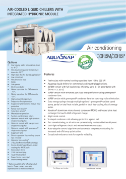

© Copyright 2026