
Owners Guide - DuraComm Power Supplies
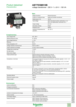
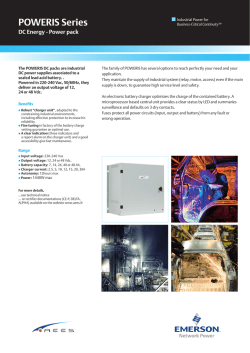
HE1U‐2524‐BMS High Efficiency 1U AC to DC Power Supply Owners Guide (These instructions are intended for use by a technician familiar with electronic products) Integrated Smart Charger Integrated Low Voltage Disconnect Selectable Input Voltage 110 or 220 VAC Remote control ON/OFF DC-OK TTL signal Short Circuit / Overload / Over Voltage / Over Temperature Protection Manual Battery Disconnect Switch 3 year warranty DESCRIPTION The HE1U-2524-BMS is a Heavy Duty AC to DC 750 Watt Power Supply with a 120 Watt smart charger and low voltage disconnect in a 1U chassis. The HE1U-2524-BMS comes with power factor correction, and four layers of protection against overload, over voltage, over temperature, and short circuit. This model also comes with a manual battery disconnect switch, internal power supply ON/OFF remote control, and DC-OK. The HE1U-2524-BMS comes with a 3 year warranty. SPECIFICATIONS Output Voltage ..........................................................................................................................................................................28 VDC Output Voltage Tolerance .......................................................................................................................................................... +/- 1 % Output Amperage ........................................................................................................................................................ 26.5 Amps max. Maximum Power, continuous ................................................................................................................................................ 750 Watts Maximum Ripple and Noise ........................................................................................................................................ 150 mV p-p max Input Voltage, Switch Selectable ................................................................................................................................. 110-or 220 VAC Input Frequency Range ...........................................................................................................................................................47-63 Hz Maximum AC Current ............................................................................................................. 8.2 Amps/115 VAC; 3.9 Amps/230 VAC Typical Efficiency ....................................................................................................................................................................... 90.5 % Max Inrush Current, single cycle ........................................................................................... 25 Amps / 115 VAC, 40 Amps / 230VAC Short Circuit Protection .................................................................................................................................Constant Current Limiting Overload Protection (operates) ................................................................................................................................. typical 105-125 % Line Regulation ....................................................................................................................................................................... +/- 0.5 % Load Regulation ...................................................................................................................................................................... +/- 0.5 % Fan Control ................................................................................................................................... Heat sink temp >140 F (60 C) = ON Over Temperature ........................................................................................................................ >195 F (90 C) auto output shutdown Rise Time following ON ............................................................................................................................................................... 50 mS Hold Time following OFF ............................................................................................................................................................. 10 mS Working Temperature Range ............................................................................................................. -22 F to +158 F (-30 C to +70 C) Storage Temperature ......................................................................................................................... -40 F to +185 F (-40 C to +85 C) Withstand Voltage .................. 3 KVAC @ 10 ma (I/P-O/P)/1 min, 2 KVAC @ 10 ma (I/P-FG)/1 min, 500 V @ 10 ma (O/P-FG)/1 min Dimensions ...................................................................................................................................................1.75” H x 19” W x 10.7” D Weight .........................................................................................................................................................................................8.4 lbs 1 of 5 January 28, 2015 BATTERY BACK UP & CHARGER Maximum Power, continuous (Battery Charge) ..................................................................................................................... 120 Watts Auto-revert to Battery or Power Supply ................................................................. provided by dual Shottky diode in OR configuration Maximum Output Current in Battery Mode ..................................................................................... 75 Amps (limited by Shottky diode) Maximum Charge Voltage ......................................................................................................................................................27.6 VDC Maximum Recharge Rate.............................................................................................. 4.3 Amps with auto sensing of charge current Charger Protection ........................................................................................Overload/voltage/temperature/reverse polarity protected Dead Battery Protection ............................................................................... Short circuit protected with deep discharge start function AC Input .................................................................................................................. 88-132 / 176-264 VAC, 47-63 Hz, switch selected Visual Indication ...................................................................... Bi color LED indication: Red = high rate charge, Green = Float charge LOW VOLTAGE DISCONNECT with RELAY Maximum Interrupt Current / continuous current ............................................................................................................... 75 Amps DC Disconnect Voltage ...................................................................................................................................................................20 VDC Reconnect Voltage ....................................................................................................................................................................25 VDC Disconnect Delay ..................................................................................................... 2 minutes @ less than preset disconnect voltage INSTALLER NOTES NOTE: DO NOT block any of the cooling vents on the sides and top and always allow adequate ventilation by not installing the unit inside tightly closed spaces. Physical mounting position is not critical but the cooling vents must not be blocked. NOTE: The outputs are NOT referenced to the chassis. The Modular System can be used either positive or negative ground. 2 of 5 January 28, 2015 INSTALLATION BLOCK DIAGRAM HE1U-2524-BMS Wiring Layout This system setup will provide continuous power to the load and maintain the battery bank with smart charger while AC power is on. There is a seamless transfer of the load to the battery when the AC power goes off. The LVD will disconnect the battery if the voltage drops below 20 VDC. The battery reconnects once AC power is restored and voltage reaches 25 VDC. 3 of 5 January 28, 2015 CONDUCTOR PRETREATMENT All kinds of copper conductors can be clamped without treatment. DO NOT solder tin stranded conductors. The solder yields and fractures under high pressure. The result is increased contact resistance and excessive temperature rise. Additionally, corrosion has been observed due to the fluxes. Notch fractures at the transition from the rigid tinned part to the flexible conductors are also possible. Ferrules can be used as a protection when wiring stranded conductors. Copper ferrules prevent the current transfer from being influenced by dissimilar metals and remove the risk of corrosion. Always use the correct tool to crimp the ferrule. RECOMMENDED COPPER WIRE SIZE FOR CURRENT CAPACITY (Insulated Wire, Single Conductor in free air) Current Level in Amperes <7 AMPERES Wire Size 20 AWG Up to 5 feet 18 AWG Up to 10 feet 18 AWG Up to 5 feet 16 AWG Up to 10 feet 16 AWG Up to 5 feet 14 AWG Up to 10 feet 14 AWG Up to 5 feet 12 AWG Up to 10 feet 12 AWG Up to 5 feet 10 AWG Up to 10 feet 10 AWG Up to 5 feet 8 AWG Up to 10 feet 8 AWG Up to 5 feet 6 AWG Up to 10 feet 6 AWG Up to 5 feet 4 AWG Up to 10 feet 14 AMPERES 20 AMPERES 30 AMPERES 40 AMPERES 50 AMPERES 70 AMPERES 100 AMPERES 4 of 5 January 28, 2015 LIMITED WARRANTY DuraComm warrants to the initial end user, each power supply manufactured by DuraComm to be free from defects in material and workmanship, when in normal use and service for a period of three years from the date of purchase, from an authorized DuraComm dealer. Should a product manufactured by DuraComm fail or malfunction due to manufacturing defect, or faulty component, DuraComm, at its option, will repair or replace the faulty product or parts thereof, which, after examination by DuraComm, prove to be defective or not operational according to specifications in effect at the time of sale to the initial end user. The product that is replaced or repaired under the provisions of this warranty, will be warranted for the remainder of the original warranty period, only, and will not extend into a new three year warranty period. The limited warranty does not extend to any DuraComm product which has been subject to misuse, accidental damage, neglect, incorrect wiring not associated with manufacture, improper charging voltages, or any product which has had the serial number removed, altered, defaced, or changed in any way. DuraComm reserves the right to change, alter, or improve the specifications of its products at any time, and by so doing, incurs no obligation to install or retrofit any such changes or improvements in or on products manufactured prior to inclusion of such changes. DuraComm requires any product needing in or out of warranty service to be returned to DuraComm. All requests for warranty service must be accompanied by proof of purchase, such as bill of sale with purchase date identified. DuraComm is not responsible for any expenses or payments incurred for the removal of the product from its place of use, transportation or shipping expenses to the place of repair, or return expenses of a repaired or replacement product to its place of use. The implied warranties which the law imposes on the sale of this product are expressly LIMITED, in duration, to the three (3) year time period specified herein. DuraComm will not be liable for damages, consequential or otherwise, resulting from the use and operation of this product, or from the breach of this LIMITED WARRANTY. Some states do not allow limitations on the duration of the implied warranty or exclusions or limitations of incidental or consequential damages, so said limitations or exclusions may not apply to you. This warranty gives you specific legal rights which vary from state to state. This warranty is given in lieu of all other warranties, whether expressed, implied, or by law. All other warranties, including WITHOUT LIMITATION, warranties of merchantability and fitness or suitability for a particular purpose, are specifically excluded. DuraComm reserves the right to change or modify its warranty and service programs without prior notice. DuraComm® Corporation 6655 Troost Avenue Kansas City, MO 64131 Phone (816) 472-5544 Fax (816) 472-0959 www.duracomm.com 5 of 5 January 28, 2015


© Copyright 2026