
Simulation software: not the same yesterday, today or
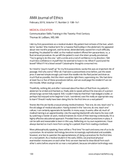
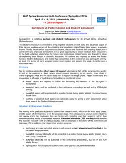
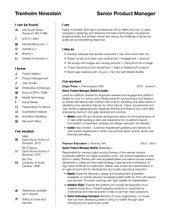
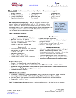
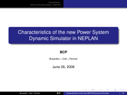
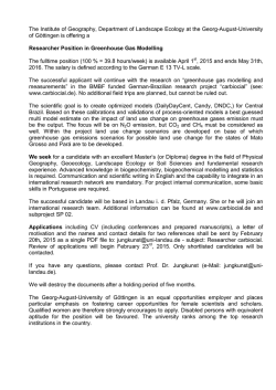
Journal of Simulation (2006), 1–14
r 2006 Operational Research Society Ltd. All rights reserved. 1747-7778/06 $30.00
www.palgrave-journals.com/jos
Simulation software: not the same yesterday,
today or forever
M Pidd* and A Carvalho
Lancaster University, Lancester, UK
It is probably true, at least in part, that each generation assumes that the way it operates is the only way to go about
things. It is easy to forget that different approaches were used in the past and hard to imagine what other approaches
might be used in the future. We consider the symbiotic relationship between general developments in computing,
especially in software and parallel developments in discrete event simulation. This shows that approaches other than
today’s excellent simulation packages were used in the past, albeit with difficulty, to conduct useful simulations. Given
that few current simulation packages make much use of recent developments in computer software, particularly in
component-based developments, we consider how simulation software might develop if it utilized these developments.
We present a brief description of DotNetSim, a prototype component-based discrete event simulation package to
illustrate our argument.
Journal of Simulation (2006) 0, 000–000. doi:10.1057/palgrave.jos.4250004
Keywords: simulation software; Microsoft.NET; composability; the future
Introduction
It will be very obvious to readers of this new journal that a
computer can be used to simulate the operation of a system
such as a factory or call centre, but whether it was so
obvious to the pioneers is not so clear. It is clear, though,
that when they realized the possibilities they were creative
and enthusiastic in developing methods that would harness
the emerging power of computers to the improvement of
productive systems. When computer simulation began, there
were no programming languages in the sense that we
understand them today. Instead, the earliest simulation
modellers found themselves flipping switches or writing in
machine code and, a few years later, writing in assembler; all
rather clumsy. More than 50 years later, computer simulation methods are taken for granted in many areas and there
are easy-to-use tools that enable people with limited
computing skills to develop and run simulation models
(Hollocks, 2004). Our aim, here, is to review the developments that occurred in that half century, trying to do justice
to the pioneers and to those who have moved things on since
then. About 20 years ago, one of us reviewed developments
in simulation and linked these to developments in computing
(Pidd, 1987), but much has changed since then.
Nowadays, computer simulation is rather a broad field
with applications in all scientific disciplines: indeed much of
climate science is wholly based on simulation models, many
of which are impossible to validate in any sense. Simulation
*Correspondence: M Pidd, Department of Management Science, Lancaster
University Management School, Lancaster University, Lancaster LA1
4YX, UK.
E-mail: [email protected]
methods are also common in the various sub-disciplines of
the social sciences and management sciences. Since this new
journal is published on behalf of the Operational Research
Society, we focus on simulation as used in OR/MS
(operational research/management science)—but there is
much more to simulation than this. Within OR/MS, the
term ‘computer simulation’ covers discrete event simulation,
continuous simulation, system dynamics and agent based
modelling. Since we have too little space to cover every
aspect of simulation, even in OR/MS, here we concentrate
on discrete event simulation.
A well-rounded discrete event simulation modeller requires three related skill sets. First, expertise in and
knowledge of probability and statistics, since many systems
modelled by discrete event simulation contain elements that
are best represented stochastically. This does not mean that
simulation modellers must be professional statisticians, but
they really should be comfortable with statistical variation
and probability. Secondly, modellers need expertise and
experience in computing, since discrete event simulations are
implemented in computer programs. It would be a mistake,
however, to assume that modellers require fully developed
programming skills in the sense that this would have been
meant 20 years ago. As will become clear later in this paper,
many, possibly most, discrete event simulations are implemented in modelling packages. These are often known as
Visual Interactive Modelling Systems (VIMS) and, although
they do require some programming, this consists of small
sets of logical statements rather than full programs. Thirdly,
and perhaps less obviously, discrete event simulation
modellers must be able to model. That is, they must learn
2 Journal of Simulation Vol. ] ], No. ] ]
the skills of extracting the essence from a situation,
embodying these in a conceptual model and using them
once they are implemented in a suitable computer system to
draw inferences about the system being simulated.
One of us, Pidd, is a management scientist who has been
involved with computer simulation for over 30 years. During
this period, he has maintained an interest in both the theory
and practice of simulation, especially of discrete event
simulation; though with more than a passing interest in
system dynamics. The other, Carvalho, is an experienced
computer scientist who, at the time this paper is written, is
close to completing a PhD in computer simulation, as part of
which she developed DotNetSim which is described later.
Our joint insights form the basis of this paper, which we
hope will be of value to people in considering not just the
past of simulation but also its possible future. Over the years,
a symbiotic relationship has developed between simulation
and computing. In general, computing has been ahead of
discrete event simulation; that is, simulation modellers have
taken up developments that occurred elsewhere in computing. But there have been exceptions to this rule, such as when
object orientation first appeared in the simulation programming language SIMULA (Dahl and Nygaard, 1966) and
also in the use of graphics for decision support.
In general, we consider the strong links between discrete
event simulation and developments in computing over the
last half century and suggest that, useful though they are,
today’s simulation packages may need to be radically rethought if they are to meet users’ future expectations. For a
broader treatment of developments in simulation see
Robinson (2005) who discusses issues beyond software.
Developments in computing and their effect on discrete
event simulation
It may once have been true that simulation modellers were
pleased to find any way to run even a simple simulation
model. Anyone who has written a reasonably complex
program in a language like FORTRAN or C þ þ knows the
feeling of relief when it seems to work properly—and the all
too common despair when a bug appears later. Eventually
the program will be declared fit for purpose, but behind this
will have been many bugs and development problems sorted
out one by one, in a laborious process of debugging and
verification. Nowadays, the existence of VIMS allows a
modeller to take for granted that a simulation model will run
once it has been built. Models can be built very quickly,
sometimes while the client for the work is watching and
taking part in the work. In the early days, a huge proportion
of the effort in a simulation project involved getting a model
into a computable form, so it could be used. That is;
programming, testing and refinement. Nowadays, thanks to
simulation tools, the emphasis is on the conceptualization
and use of a model to think through options for change or to
develop understanding. That is, modern simulation tools
have shifted the emphasis from programming and software
development to modelling and model use—at least as far as
simulation modellers are concerned. Of course, hidden away
in the background are the software engineers and developers
who provide the tools that have enabled this shift.
A quick review of the history of discrete event simulation
software
Without over-simplifying matters too much, we can consider
discrete event simulation software as passing through the
following phases.
1. Almost any programming language can be used to write a
discrete simulation application from scratch, as long as it
supports both numerical computation and logical operation. Thus, people have used FORTRAN, Pascal,
BASIC, Modula II, C, C þ þ and the variations around
these languages. Since common operations occur in any
discrete event simulation, programmers were quick to
develop libraries of subroutines and functions that could
be re-used. Initially, such re-use was for a single
individual or organization, but gradually products such
as GASP (described in Pritsker, 1974) and SIMON (Hills,
1965), which were libraries of subroutines, appeared in
the market. SIMON, a library of Algol routines, was sonamed because its originator, Robin Hills, intended it to
be simple to use—compared to the available alternatives.
Today, some simulations are still written by cutting
general-purpose code, but probably very few of these are
in the commercial world.
2. Since computer programming skills have rarely been
widespread, simulation software developers realized that
users without proper programming skills could be
supported by the development of application packages
based around the idea of a flow diagram, sometimes
known as a block diagram. Early examples of these were
GPSS (described in Gordon, 1962) and HOCUS (Hills,
1971). As originally envisaged, such models would be
developed in a two-stage process. First, the user would
draw a flow diagram that represented the outline of the
logic of the system to be simulated. Secondly, this logic
would be translated by the modeller into a command
sequence (using punched cards in the early days) that
would be read by the flow/block diagram system (eg
GPSS) as data. As long as the application was relatively
simple, the simulation could then be run. However, such
flow diagrams can rarely capture the full logic of a
simulation application and further development was
needed. Since an experienced modeller could write down
a series of GPSS block commands without drawing a
diagram, systems such as GPSS came to be regarded as
simulation languages and the idea of a GPSS ‘program’
appeared.
M Pidd and A Carvalho—Simulation software 3
3. Once the idea of a simulation program as a sequence of
high-level commands is accepted, it starts to become
sensible to develop full programming languages that
incorporate commands that execute operations frequently
used in a simulation. In this way, GPSS eventually
became GPSS/H (Crain, 1996), moving away from its
roots in flow diagrams by adding limited program control
constructs. Also employing a block structure, Pegden
developed SIMAN (described in Pegden et al, 1990),
which included the concept of a simulation experiment, or
frame, linked to the simulation model. SIMSCRIPT
(Markowitz et al, 1963) and its descendent SIMSCRIPT
II.5 (Russell, 1987) also appeared; as did CSL (Buxton
and Laski, 1963) and ECSL (Clementson, 1973). With the
benefit of hindsight, the queen of these simulation
languages was SIMULA (Dahl and Nygaard, 1966),
which introduced the concepts now included within
object orientation.
4. These language developments were also accompanied by
the creation of interactive program generators, of which
the best known was perhaps CAPS/ECSL (Clementson,
1982), although the ideas first appeared in Ginsberg et al
(1965). These required the user to develop a flow diagram,
which was described graphically or in text to the program
generator, which then wrote code that would compile and
run and, most significantly, could be edited to add those
tweaks that were impossible to represent on the flow
diagram. It should be noted, though, that editing
someone else’s computer program requires advanced
skills and some confidence and so these program
generators were not widely used.
5. As PCs grew cheaper and more powerful, they also
provided inexpensive and high-quality graphical displays.
Especially in the UK, simulation software developers
were quick to capitalize on this and, building on
Hurrion’s work at Warwick University (Hurrion, 1976),
Istel developed SEE-WHY (Fiddy, Bright and Hurrion,
1981) and an offshoot of British Steel developed FORSSIGHT (Business Science Computing, 1982). These were
Visual Interactive Simulation (VIS) packages that
allowed animations of model performance to be displayed
on-screen as a simulation ran and permitted the user to
interact with the model in a gaming mode. However, they
still required the user to write code—typically in
FORTRAN.
6. These VIS were quickly followed by VIMS in which the
user develops the core of a simulation model by placing
and linking icons from an on-screen palette. Detailed
event logic is added by allowing the user to write event
code in property sheets that are linked to the on-screen
diagram. The first such VIMS that enjoyed any success
was probably Witness, created by Istel (Gilman and
Watramez, 1986), which was quickly followed by many
others: including ProModel, Automod and Taylor II. A
quick glance at the software on display at conferences
such as the Winter Simulation Conference or at the
biennial simulation software survey conducted by Jim
Swain for INFORMS (Lionheart Publishing, http://
www.lionhrtpub.com/ORMS.shtml) shows that VIMS
now rule the roost.
Package bloat
Hence, simulation modellers have moved from a state
in which they were pleased to get any computer simulation
to run, even a simple one, after days of tedious debugging.
We now find ourselves with a wide range of VIMS
well-suited to specific application domains and, by using
them, we can quickly develop a simulation model that
will run. However, like most software, discrete event
simulation packages have begun to show signs of package
bloat. That is, the relatively simple idea of a simulation
executive that dynamically executes the static logic laid out
in event, process or activity code has ended in a situation in
which the typical package is, effectively, a simulation
modelling and support environment that provides the
following:
Modelling tools, such as
* A graphical modelling environment.
* Built-in simulation objects (eg machines, conveyors)
with defined properties and behaviour.
* Property sheets and visual controls to enable simulation
parameters to be set and varied.
* Sampling routines and other utilities employed in the
model.
Tools to execute the simulation, such as
* A simulation executive to run a model.
* Animated graphics or virtual reality representations to
allow a user to view the model state as the simulation
proceeds.
* Simulation run control to enable the user to interact
safely with the simulation as it runs.
Tools to support experimentation, such as
* Experimental frames that define run lengths, outputs
and parameters.
* Analysis tools that enable results to be interpreted and
presented.
* Optimization tools.
Links to other software such as spreadsheets, databases
and corporate systems.
Figure 1 shows a hypothetical but typical simulation
package and its various components that provide the above
functionality.
4 Journal of Simulation Vol. ] ], No. ] ]
Code generators
Debuggers, Interpreters
and compilers
Libraries of
prefabricated objects
Legend
Data Input Analysis
(ExpertFit, Sat::Fit, …)
Graphical Editor
Graphics generators
(predefined user-defined
graphs,…)
(Designing the
model layout)
Report generators
(predefined user-defined
reports,…)
Output analysis
Optimisers
(OptQuest,…)
3D representation and
animation
Rules Editor
(adding logic and
data to objects
and connections)
Simulation
programming
language
General purpose
programming
languages
Core
application
Add-ons
External
components
Simulation engine
(running scenarios)
Core application
Templates
(classes of problems)
Wizards to generate
models
Access to external
data sources
General-purpose packages
ExpertFit, Stat::Fit, Oracle, Microsoft Office, ...
Figure 1
A typical simulation package currently consists of a core application, and a wide range of add-ons.
Hence, modellers expect discrete event simulation software packages to present themselves as huge, monolithic
applications that aim to do almost everything. They possess
functionalities that are constantly extended by adding
wizards, templates, etc in a generalizing–customizing–
generalizing development cycle. This has happened because
simulation software vendors, like other software suppliers,
have been trapped by their own success. It has been easier to
add features, however inelegantly done, than to design again
from scratch. In this way, most current simulation packages
have enough functionality to cope with a large number of
problems, but may be an evolutionary dead-end.
Most of these packages were designed with a particular
application domain in mind, usually manufacturing. However, they have enjoyed success in other areas that could
hardly have been imagined by their originators, and their
pre-defined object libraries have grown to accommodate this
broad range of applications. This approach, however
successful, may be reaching its limits and other development
alternatives should be considered in order to support robust,
easy-to-use, quick-to-develop, quick-to-change and quickto-run simulation software solutions. In doing so, it is
sensible to resort to the latest advances in component-based
and layered-based paradigms, and integration mechanisms
to promote the composition of simulation software solutions
from existing or newly developed prefabricated components.
A quick review of software development paradigms
In order to see a better way forward for discrete event
simulation software, it is necessary to quickly review
successive software development paradigms. Understanding
this explains much of why simulation software has taken its
form and also suggests how a different approach might be
used in future. The review here begins in the 1970s, when
computer programming was an established skill but most
programs were developed in languages such as FORTRAN
and COBOL, in versions that now seem very crude. The use
of such languages led to a crisis in software development in
which it became clear that there was a need for standardization and for approaches that ease software development and
subsequent maintenance.
Theoretical frameworks or paradigms were successively
designed to provide programmers with a set of laws, rules
and generalizations that enable programs to display desirable properties. Naturally, there are different paradigms for
different programming domains as these also target different
sets of desirable properties. Our scope is however confined to
application software for simulation and hence Table 1 lists
some of the desirable properties for simulation software. It
should be no surprise, though, that virtually all application
software has similar core requirements; that is, to software
professionals, many core simulation software requirements
are the same as those in other application domains. Hence, it
is worth reviewing four programming paradigms, each of
which was intended to support the development of software
with these properties.
1. Structured programming (Dahl et al, 1972) was the first
formal programming paradigm on which others where
built. Modularity and its implicit ‘divide and conquer’
M Pidd and A Carvalho—Simulation software 5
Table 1 Desirable properties of simulation software
Property
Brief description
A program should
Dependability
Ability to deliver the intended functionality when
requested without causing danger or damages,
resisting external attacks (Sommerville, 2004) and
handling error conditions.
Ability to provide friendly user interfaces that permit
different levels of utilisation, detection and recovery
from input errors.
Ability to be incrementally built by composition of
self-contained units—functions, procedures, modules,
components, etc.
Ability to run on different configurations, be
composed with other programs and to communicate
with packages of different vendors
Be reliable, available, safe, secure and robust.
Usability
Modularity
Reusability
principle were its most important contributions to
programming. It advocates techniques to structure the
program’s flow control that are still recommended so as
to make programs easier to read and to maintain.
Structured programs are sets of modules, which are, in
turn, sets of procedures or functions. Procedures may
invoke themselves or other procedures and functions to
manipulate local and global variables. The program runs
by passing data through parameters among procedures.
Although functions and procedures can be re-used by
lifting them from one program and pasting them into
another, it remains true that structured programs are
monolithic pieces of code developed from scratch or,
sometimes, from scavenged code.
2. Functional and logic programming paradigms (Bird and
Wadler, 1998) and their combination emerged within the
artificial intelligence community in the early 1990s. They
led to declarative programming paradigms, that is, they
focus on the description of data’s relationships, either
mathematically or logically, as a means to approach
human modes of thought.
Functional programming approaches derive from the
Church’s-Calculus (Church, 1941) and, therefore, consist of sets of functions that produce values or other
functions, once applied to their arguments. The
execution of a functional program deals with the
evaluation of expressions and their replacement by
the corresponding values. This implies referential
transparency, that is, functions must not produce side
effects, since it is crucial to guarantee that the
application of a function to the same argument always
returns the same result. Functional programming
originated heavily recursive languages such as Lisp,
Miranda and Haskell, which are intuitive but lead to
programs that are memory-demanding and slow to run.
Logic programming derives from the first-order predicate calculus, hence the outputs of a logic program
are inferred from the known facts and the relationships
between a set of objects. Prolog is the commonest logic
Be easy to learn and operate, adaptable to specific
models of work, and recoverable from user errors.
Be modularly composed and extendible.
Be portable, integrable and interoperable
programming language and is used mainly for expert
systems.
Functional logic programming paradigms combines
these two paradigms so that the programming primitives have the power of logical inference, in for
example, non-deterministic search and the efficiency
of the functional evaluation strategies such as lazy
evaluation. ALF, Babel and Curry are examples of
functional logic programming languages.
3. Object-oriented programming (OOP) (Booch, 1994;
Meyer, 1994) originated with Simula, an Algol-based
language that supported discrete simulation. The application of OOP in simulation is demonstrated in Pidd (1995)
and is based on the notion of objects, their attributes and
the functionalities they provide. An object is a data
structure composed of data (attributes) and code
(methods) that implement the object’s functionalities.
For example, a queue is an object with attributes such as
queue name, location and discipline and methods that
enqueue and dequeue elements, determine the length of
the queue at each state, reverse the queue, etc. Objects
interact by invoking methods of other objects, that is, by
requesting others to execute the functionalities they
provide. An observer service, for example, may be
another object that interacts with the queue by invoking
its methods to enqueue and dequeue clients and compute
performance indicators. Several programming languages
implement OO concepts. Some are fully object-oriented
such as C# and VB.NET. Others, such as earlier versions
of Visual Basic and corresponding subsets (VBA) are not
fully OO languages as they do not implement inheritance
and offer limited utilization of abstraction and polymorphism.
Classes are fundamental to OO programs. A class is an
abstraction of an object that defines the attributes and
methods of a family of objects. An object is therefore a
class’s concretization. For instance, the class Queue is a
generalization of all queues and the object ‘Queue for
6 Journal of Simulation Vol. ] ], No. ] ]
the Teller A’ is an instance of that class. A class gathers
together, in a self-contained unit of code, attribute
declarations (properties or field variables) and methods
that allow the creation, at runtime, of objects
(instances) with all the specified functionality of the
class. The class encapsulates all its contents within itself
and only exposes the information required for the
invocation of its methods.
Inheritance mechanisms allow classes to be organized
into hierarchies of super-classes and sub-classes. Subclasses inherit the attributes and methods of the superclasses from which they are derived, and may add
more attributes and methods, which are then passed to
their own sub-classes. For instance, the B and C
activities of the three-phase simulation worldview are
both activities that share attributes such as name
and description, and methods such as those to set and
get the common attributes. Hence, B_activity and
C_activity classes may be derived from the super-class
Activity. In addition, these sub-classes may also have
their own attributes and methods: for example, a
C_activity has attributes and methods associated with
the condition that determines its execution but these
are not present in a B_activity, nor in the Activity
super-class.
Polymorphism allows a method of a super-class (or an
interface) to be implemented differently in any of its
subclasses. At runtime, the implementation of this
method in a sub-class overrides its implementation in
the super-class. Thus, this method appears in many
forms depending on the context of its implementation.
For example, if the super-class Event of a discrete event
simulation defines a method for updating the state
variables, it is likely that this method has different
implementations in each event routine. Also, methods
may need to refer to collections of different objects
whose types are only known at runtime. Polymorphism
allows the definition of generic objects that suit
different types and at runtime they will assume the
type of the given object.
4. Component-oriented programming extends OOP concepts
to provide a framework for constructing programs from
prefabricated OO pieces of code (components). A
component is a software artefact that is independently
deployable, compose-able by third-parties and with no
observable external state (Szyperski, 2002). To meet these
requirements, components must be self-contained and
encapsulated units that, by exposing the functionalities
they offer and the needs for their delivery, can be plugged
into (and unplugged from) other components. It is
important that they are immutable, in the sense that they
are abstract definitions and consequently two copies
provide exactly the same functionality under the same
conditions.
Fine-grained components provide limited functionality
and typically deal with detailed data structures. Hence,
they tend to be specific and dependent on the
deployment environment (they may even include
operating system basic functionality). Many finegrained components are rather like the FORTRAN
subroutines and C functions widely available for
generating random numbers: they are small and
perform a single, well-defined task.
On the other hand, coarse-grained components deal with
large-scale data structures and have a high degree of
abstraction that makes them generic and adaptable to
several deployment environments.
5. Layer-oriented programming (LOP) paradigm applies
mainly to the design of system architectures and is
concerned with the interconnection of software components. A layered system is incrementally built, layer upon
layer (Szyperski, 2002). LOP inspired the OSI reference
model (Tanenbaum, 2002) and was first used to develop
onion-structured operating systems (Deitel et al, 2003).
Each layer receives from the layer immediately below
well-defined functionality, which it increments and passes
to the layer immediately above. Each layer may be
composed of several components. LOP is associated with
meta-programs that provide the functionality to interpret,
inspect, adapt and extend the structure and behaviour of
the underlying software. The metadata (attributes) and
computational reflection allow for the dynamic composition of layers of components. This presents the possibility
of on-demand software programming (Elfatatry, 2002;
Elfatatry and Layzell, 2004) based on the dynamic
assembly of software solutions by selecting, negotiating
and invoking suitable components, as web services, at
runtime. Simulation systems could be constructed with
layered structures, for example, by adding layers as
shown in Figure 2. This is a pyramid-layered structure
(Moses, 2001, http://esd.mit.edu/HeadLine/mosesspeaks.
html, accessed 21 March 2005) in which each layer
receives from its immediately lower layer the necessary
functionality to provide more specific and finer grained
functionality.
Software developments and their impact on simulation
software
Early simulation texts (eg Fishman, 1973) stressed that a
computer program that executes a discrete event simulation
has three main parts as shown in Figure 3. These are firstly, a
simulation executive that manages simulation time and
ensures that the events of the simulation are executed at the
correct time and in the correct sequence. It does this by
maintaining an event list, or calendar, into which future
events are added and from which events are executed when
Specific simulation
solution
Concretisation
Fine-grained functionality
………..
………… ...
Domain-specific simulation template
Simulation library of components
Simulation development framework
General-purpose development functionalities
Hardware and operating system functionalities
Figure 2
Coarse grained functionality
Abstraction
Pyramid composition of a simulation system.
Simulation executive
Logical
operations
Utilities
Discrete event simulation program
Figure 3
Composed by analysis
Decomposed by syntesis
M Pidd and A Carvalho—Simulation software 7
Inside a discrete event simulation program.
the correct simulation time is reached. There are many ways
in which the calendar and event management can be
implemented, but the principles are consistent. Once the
concept of a simulation language was established, the
executive was provided by the simulation language developer
and used by the modeller when developing an application.
The second part of Figure 3 is a set of utilities, also
provided by the language vendor and used by the modeller
for particular applications. The utilities perform common
simulation tasks such as random number generation,
random sampling from defined distributions, list management and maintenance for keeping track of simulation
entities, debugging tools and report generators. To these, the
experienced modeller may add his/her own utilities based on
the requirements of his/her own application domain.
The third part of Figure 3 is the set of routines that
capture the dynamic logic and interactions that underpin the
operation of the simulation as it proceeds over time. How
these are labelled and implemented will depend on the
simulation world-view in place (event-based, activity-based,
process-based or three-phase) and the programming language in use. It is the task of the simulation modeller to
determine what events/activities/processes are required and
to program them in a parsimonious way. These events/
activities/processes are controlled by the simulation executive and communicate with it by defined protocols as the
simulation proceeds.
This well-defined structure is characteristic of the way in
which simulation packages and programs were implemented
from the late 1960s onwards. Its affinity with structured
programming, as introduced above, should be obvious. It is
unclear whether the architecture of Figure 3 emerged
because it coincided with the introduction of structured
programming ideas or whether the obvious structure drove
simulation software developers toward structured programming. Certainly, though, the two have been happy bedfellows and continue so to this day.
Inside a typical VIMS
To demonstrate this continued, apparently happy, symbiosis
between simulation programs and structured programming,
consider the typical internal organization of a VIMS shown
in Figure 4 (taken from Pidd, 2004). It presents a user
interface that exploits the API of what-ever operating system
is in place (usually a version of Windowst). Within this, the
user will be allowed to develop a model, to edit an existing
model, to run a model and to conduct controlled experiments. The latter usually allows at least some statistical
analysis, and the export of results files in some suitable,
external format. Models are constructed by selecting icons
that represent features of the system being simulated and
these are linked together on-screen, and parameterized using
property sheets. This is fine if the objects provided are a
good fit for the application. However, the default logic
provided by the simulator may be inadequate to model the
particular interactions of specific business processes. To
allow customization, most VIMS provide a coding language
in which interactions can be programmed. Some offer links
with general-purpose programming languages (eg Visual
Basic). Others incorporate simulation quasi-language logic
builders that permit little beyond the assignment of
attributes, the definition of if statements, loops and limited
access to component properties. Some of the limitations of
these languages and their part in VIMS are discussed in
Melao and Pidd (2006).
8 Journal of Simulation Vol. ] ], No. ] ]
USER INTERFACE
model builder
& editor
simulation
engine
simulation &
application
classes
generic model
Model
development
Figure 4
Model
running
analysis &
experimentation
toolkit
Experimentation
Internal organisation of a typical VIMS.
Underneath the user interface is a generic simulation
model that is presented to the user in one of two ways,
sometimes both. The most common way, as seen in Witness
and similar packages, is that of a machine network in which
parts flow from workstation to workstation. For example, a
part may go to a lathe, then through a washer, then to an
inspection point and then into a shrink wrapper etc. A
workstation may well be able to carry out more than a single
task and may be able to cope with more than a single type of
part. As parts flow through the network, they sit at a
workstation for a time, possibly stochastic, often known as
the cycle time. As a result of their interaction with the
workstation during the cycle time, the parts change state.
Parts are routed through the machine network and each
machine must be parameterized by the completion of a sheet
that specifies its predefined properties.
By contrast, systems such as Micro Saint Sharp offer a
task network that represents the sequence of tasks through
which the main entities of the simulation will flow. Thus,
passengers may disembark from an aircraft, may walk to
immigration, may be processed in immigration, walk to the
baggage hall, etc. Each task requires resources for its
completion and tasks may compete for resources. The
resources required and the conditions governing the start of
the task are specified in a property sheet, along with the
consequences of the task.
Of course, these two types of VIMS network are
equivalent; much as the dual formulation of a mathematical
programming problem is equivalent to its primal. That is,
with suitable imagination, an application that appears to be
a sequence of tasks may be modelled as a machine network
and vice versa—however, choosing a horse for the right
course can make life much easier.
Inside every VIMS is a generic simulation model that is
not usually available to the user to edit. In essence, the
generic model takes the network diagram as data, much as
GPSS was designed to take a series of punched cards that it
then interpreted. Thus, if it were thought desirable, a VIMS
on-screen network could be replaced by a series of textual
commands each of which carries attribute and method data
to represent the data of the property sheets. The generic
model assumes that simulation entities change state and it
reads the network description to define the sequence of those
states and the conditions that govern them. Code fragments,
in whatever simulation language, are then used to modify the
generic model in some way or other. That is, a VIMS
provides much of the dynamic logic (Part 3 of Figure 3)
needed in a simulation model and this communicates with,
and is controlled by, a hidden simulation executive. Likely as
not, the generic model and executive will have been written
in a structured programming language, although some show
signs of object orientation.
Although this approach works very well, it does have a
couple of significant problems. The first is that an
experienced modeller is unable to do much in the way of
extending or customizing the VIMS to better fit her own
circumstances. Although some packages allow the user to
develop her own simulation objects, this is usually very
limited—possibly not surprising, since VIMS are sold,
primarily, on the basis of ease-of use. However, while
providing software that is promoted as easy to use, the
vendors must also provide enough support and flexibility for
the VIMS to be used in applications of some complexity and
scale. As discussed earlier, this has led to package bloat,
which is the second problem with this approach.
There is another way
The past and the current evolution of simulation software
lead us to expect that simulation software will continue to
rely on the latest advances in computer science to support
computer simulations of increasing size and complexity.
Progress achieved in areas such as programming paradigms,
integration of hardware and software platforms, networks
and communications and the continuous advance of internet
technologies is crucial to the future of simulation software.
Figure 5 summarizes the parallel evolution of computing and
simulation software. Away from simulation, it seems that
computing is now evolving toward ‘on demand software’ or
instant assembly of software, in which software builders
‘rent and pay per use’ only the functionality required at
runtime. It is worth considering whether simulation software
might similarly evolve in the direction of the just-in-time
assembly of simulation solutions.
This commercial demand for customized solutions may
well force current simulation packages to be restructured so
that each user gets exactly the functionality a solution needs
or, even better, the user gets the capability to produce the
functionality a solution needs. Doing this will require
simulation software that fully complies with object-oriented,
component-oriented and layered-oriented programming
paradigms, as these support on-demand customization.
Looking further ahead, simulation software might evolve
toward on-demand component assembly and use based on
an open market of components. In this, software solutions
M Pidd and A Carvalho—Simulation software 9
On Demand
Software
Layer-orientation
Distributed
computing
Component-based
Component-orientation
Object-orientation
Structured programming
VIMS
Interactive and
graphical
computing
High level languages
Machine languages
Packaged
Portable
Computers
Computing
Figure 5
Simulation
software
Machine
Oriented
Parallel evolution of computing and simulation software.
would be built by modellers who select and assemble at
runtime the functionality needed for the specific applications
by negotiating with those who develop and publish
simulation software components as web services.
Some existing attempts
Progress in this direction has already begun. The ProModel
Process simulator (ProModel Corporation, 2005, http://
www.promodel.com/products/processsimulator, accessed 16
December 2005) is an example of a simulation package that
interfaces with another software tool, in this case Microsoft
Visiot. Visio is used to provide a graphical template in
which a business process model may be developed. In
essence, it allows the machine-based view of ProModel to be
presented as if were a task network, this being much more
useful for business process simulation modelling. These
Visio-derived models are then compiled into an appropriate
format and run by the ProModel simulation engine. While
running a model, the ProModel runtime environment and its
animation capabilities replaces the Visio modelling environment. The simulation results are displayed in the ProModel
Output Viewer 3DR in a variety of graphical and tabular
formats. These can be saved in text formats and opened in
generic applications such as Microsoft Excel. As usual,
what-if analysis is then available and different scenarios can
be saved.
This Visio-based graphical interface highlights the trend
for developers to integrate their simulation engine with
generic software in order to leverage its usability by
compliance with human–computer interaction ‘standards’.
This is certainly an improvement but it only applies to the
modelling input interface. The integration of the Visio
modelling environment and the simulation engine consists of
a black-boxed compilation into a file, which is later
automatically input into the simulation engine. The simulation engine and the output interface are still specific and
therefore not changeable by the builder or the user of the
simulation package. The user can, however, open the results
files in other applications for further analysis.
Micro Saint Sharp (Micro Analysis and Design Inc,
2004a,b, http://www.maad.com/index.pl/whats_new#mss,
accessed 16 December 2005; http://www.maad.com/index.pl/micro_saint, accessed 22 April 2006) is a second
example of a move towards component-based customization. It succeeds the earlier Micro Saint product and adopts
a similar task network as its graphical modelling template,
but uses C# as its modelling and programming language.
The C#-based logic builder enables users to define the
process logic and dynamics using a subset of this generic
programming language. User-defined functions can then be
written within the package to extend its capabilities. Perhaps
because C# is so powerful, Micro Saint Sharp handles only a
restricted subset of C# programming language with limited
OOP features. However, built-in classes, such as Model and
Task, are provided and have their own built-in functions.
The user may code methods for responding to events, that is,
beginning and ending effects. New objects with properties,
that is containers of field variables, may be created by
resorting to an object designer. But proper inheritance
is unavailable and polymorphism is limited to variant
variables.
Micro Saint Sharp is based on Microsoft’s .NET framework and uses this to offer communication modules that
simplify the access to external data by providing built-in
connectors for Excelt, Sockets, ADO, Text Files, ConsoleApplications, and Web Sites. Connectors to specific
applications can be created in C# by resorting to the
networking classes and interfaces of .NET. A ‘Plug-in
Framework’ is also provided to install user defined addins. This framework contains the signatures of the interfaces
the user has to implement in order to attach a DLL file
written within the .NET framework. Data exchange with
other applications is also supported through TXT and XLS
10 Journal of Simulation Vol. ] ], No. ] ]
Built-in
frame works
Tailored Simulation
application
Add-ins
Development tools
HighMastTM
.Net Framework
Simulation Class Library
Base Simulation engine
Operating System
Hardware
Framework Class Library
General data structures
Integration
Communication …
Basic Infrastructure
Editors, Debbugers, CLR, ….
Figure 6
HighMastt infrastructure and composition.
file formats for input and output. Thus, the core Micro Saint
Sharp simulation application can be augmented with other
software that is .NET compliant.
HighMast, Highpoint’s Modelling And Simulation Toolkit, is a .NET-based modelling and simulation framework
(Bosh,
2003,
http://www.highpointsoftware.com/highmast.htm, accessed 7 October 2003) that supports the
gradual development of software applications for running
discrete-event and continuous simulation systems. It sits on
top of the .NET framework using a layer-oriented programming paradigm as shown in Figure 6.
Unlike Micro Saint Sharp, HighMast is a source-codebased platform, but it also uses the .NET environment’s
underlying conceptual principles and relies on its integration
and communication capabilities to provide a platform for
the development of tailored stand-alone and distributed
simulation applications. Thus, it relies on object-oriented
principles, component-based development paradigms and
dynamic binding mechanisms to allow simulation applications to be built in layers of software. Users may build
specific simulation software solutions by integrating appropriate software packages, multi-lingual components and web
services with a simulation engine and pre-built frameworks.
Users can alter prefabricated components, write new ones
and assemble the whole package by using general-purpose
programming languages. The user’s tailored simulation
application can, in its turn, be constituted as a web service
available for other applications.
HighMast itself is coded in C# and consists of a
foundation simulation library and a base simulation engine.
The foundation simulation library includes classes that
implement simulation related features such as distribution
functions, event generators, resource management and graph
traversing. The base simulation engine consists of a model
class and an executive class implemented separately. The
executive class runs the model by handling synchronous
events (event-based simulation), and detachable or batched
events (process-based simulation) and committing or rolling
back the transition of each model state.
HighMast provides tools and data structures to facilitate
the integration of third-party components. Examples include
tools for database manipulation, graphic generators and
reporting allow the retrieval and display of externally
sourced data. Other tools ease the run-time plugging of
self-documenting components. Other techniques and microframeworks may become available as add-ins that can be
installed according to the user’s needs. Statistics logs, multirooted dictionaries of user-specified data structures and
modelling expressions, instant snap-shot of the current
running state, tree or tabular representation of object
hierarchies and handlers of compiled queries at run time
are already available. Its source-code and layer-based
approach enables the development of frameworks for
particular application areas. HighMast frameworks are in
development for modular supply chain models, bank teller
models and product or service transformation models.
These three examples of current developments in commercially available simulation packages illustrate a concern to
ease the task of integrating simulation software with widely
used tools such as Visiot and Excelt. In the case of the
ProModel Process Simulator, this integration is limited to
the presentation of a friendlier graphical modelling template
that provides data to the underlying ProModel simulator.
This is useful, but much more can be done. Micro Saint
Sharp and HighMast both go much further than this, being
designed to exploit Microsoft’s component-based .NET
framework and, thereby, supporting aspects of extendability
and plug and play. This allows the simulation package itself
to be based on an assembly of components and permits the
user to integrate other .NET software to meet the
requirements of a particular application. This is increasingly
important as the pressure to produce customized solutions in
shorter time increases further.
Figure 7 shows a vision for future simulation software in
which, rather than continuing the addition of extra
functionality to existing packages, vendors and others
pursue a different route. In this vision, a core simulation
application is built to support its linkage to other software
components through a defined architecture. Approaches
such as that of the ProModel Process Simulators use of
Visiot are merely a continuation of the current mode of
simulation software development. There was no attempt to
re-design the underlying simulation package, but the link to
Visiot (which is itself customisable) allows the general
package to present itself as more suitable for business
process modelling than manufacturing, which was the
original application domain of ProModel.
Micro Saint Sharp moves further towards the ideal
scenario, as its core application was re-designed within
the .NET framework so as to take advantage of objectoriented and component-based programming paradigms.
M Pidd and A Carvalho—Simulation software 11
TM
HighMast
Micro Saint
Sharp
Process
Simulator
Past
•
•
•
•
•
Huge monolithic applications
Specific software
development tools
Customisation by addition of
the features needed at the
moment
Slow and complicated
maintenance, expansion,
customisation and utili sation
………………………..
Figure 7
Ideal Future
Current experiences
•
•
•
•
•
•
•
•
•
Base simulation frameworks
and libraries of tools
Customisation by derivation of
specialised tools
Generic and specialised
development environments
Different levels of usage
Easy to learn and easy to use
Easy expansion by derivation
Run fast
Maintenance confined
………………………..
Timeline of the past, current and ideal approaches to the development of simulation software.
Its approach is based on these programming paradigms and
their implementation in the powerful C# language and
enables easier customization and interoperability with other
applications, Additional features are loaded only if required;
and new features can be written in C# and attached to Micro
Saint Sharp as DLLs. Also, the built-in tools to interoperate
with other applications can be extended by resorting to a
‘Plug-in Framework’ based on the networking classes and
interfaces of .NET. This hugely increases the capability to
connect several packages, including those for simulation,
and those to model and run distributed systems. In addition,
it provides a C#-based logic builder that allows the user to
add more complex logic to be added to the models. This is a
very restricted subset of C#, but logic that requires more
powerful programming primitives can be implemented in C#
and invoked as DLLs.
HighMast, moves even closer towards the ideal scenario.
It is really a development framework that derives from the
Microsoft .NET framework and lies above it; that is, its
vertical architecture promotes the generalize–specialize
development cycle. Theoretically, further specialization can
be built on the underlying frameworks. Their object and
component orientations allow simulation tools to be derived
from foundation libraries of tools to provide the functionality required by a simulation model. This allows computingsavvy users to produce the functionality each simulation
model requires, by combining and altering the existing
source-coded tools. HighMast offers event and processbased simulation executives, but all varieties of simulation
worldviews can be implemented. Interoperability across
computers, packages and programming languages is avail-
able through the Microsoft .NET framework. HighMast
implements an entirely new approach to the development of
simulation software applications. Theoretically, it is very
close to our ideal scenario, but does not support the dynamic
selection and assembly of components needed for ondemand simulation.
DotNetSim: exploiting these new technologies much
further
Our work with the DotNetSim prototype exploits the
Microsoft .NET integration philosophy for the progression
of simulation software along the time line toward our ideal
scenario. The idea is to explore how far the new integration
mechanisms can pull DES modelling and simulation software toward fully object-orientated components that cross
programming languages, packages and platforms and link
them in a single application that might be deployed as web
services. This approach is investigated across the entire
requirements of a simulation application package including
user interfaces, simulation executives and output analysis.
This focuses on two main development issues:
1. Data exchange between distinct software development
tools through the instantiation of objects to apply the
OOP paradigm and replace the current creation of
intermediate files and associated format conversions.
2. The integration of powerful simulation engines with
widely used packages in an architecture that supports the
straightforward modification of modelling and simulation
environments.
12 Journal of Simulation Vol. ] ], No. ] ]
Description of events and inter-event relationships
(Excel, Word, PowerPoint, Project , Access, ...
Web service
Figure 8
Modelling
Environment
Diagram
Modelling data
Model description
Simulation
Engine
C#
Output Analysis
Data Analysis
Report generators
Report Generators
Additional
components
executive. It reads the model’s logic by instantiating the
Visio modelling environment, runs the event-based simulation and returns the simulation results to Excelt for
analysis. It can also be deployed as a web service to which
the model’s logic is remotely input.
The output analysis is an Excel template that is
instantiated by the simulation engine to output the simulation results as they are produced. It implements a set of VBA
components to analyse and report the simulation results.
Excel
Visio
Overview of the DotNetSim functional structure.
The DotNetSim project addresses three major fields and
their inter-relationships: discrete event modelling (using
event graphs; Schruben, 1983), integration technologies
(using .NET) and discrete event simulation in a functional
structure shown in Figure 8.
It is important to realize that the three coarse-grained
components of the prototype could be substituted by others
that deliver the same functionality, although with different
internal operations—for example, representing alternative
simulation worldviews. For example, the prototype graphical modelling environment emulates Schruben’s event graph
methodology for simulation modelling. However, other
methodologies such as activity cycle diagrams, Petri nets
or control flow graphs could substitute for it. If required, the
same approach could be used to develop different graphical
modelling environments to suit particular application
domains, such as manufacturing.
The prototype graphical modelling environment that
supports event graphs is based on Microsoft Visio 2003t.
Event graphs are drawn by the user, or generated
automatically from Excel-based lists of attributes given the
stencil’s modelling notation. That is, the prototype allows
models to be specified graphically or via Excel tables and
each input mode can generate a model representation in the
other. Modelling data are stored in relational tables
associated with simulation events and their inter-relationships and can be reported in Wordt, Excelt and PowerPointt documents. This list could easily be extended so that
the model’s logic and dynamics, and the data reporting can
be generated or displayed within a wider range of .NET
compliant applications.
The DotNetSim graphical modelling environment uses
specially developed VBA components to link together the
different Microsoft applications by instantiating one application from within others. This supports bi-directional data
exchange in order to create the stencil’s modelling notation,
and to capture the models’ application logic and its
dynamics.
The simulation engine consists of several C# and VB.NET
components that implement an event-based simulation
Some lessons from DotNetSim
We have reviewed the history of developments in discrete
event software and have pointed out the dependence of most
existing software on procedural programming approaches
that have, in other computing domains, been replaced by
paradigms that employ components.
The working DotNetSim prototype illustrates the way
that a defined component-based architecture, Microsoft’s
.NET framework in this case, can support an approach to
the development of simulation packages that is very different
from that evident in much contemporary simulation software. Rather than aiming at a monolithic and highly
integrated application, it is deliberately assembled from a
small set of coarse-grained components—each of which is
composed of finer grained components. For the software
developer this has several advantages. First, each of the
components can be substituted by others that offer the same
interfaces and external functionality. For example, the Visiobased event graph modelling component could be replaced
by another event graph environment developed in some
other configurable graphical system that is .NET compatible. Alternatively, a different modelling approach (such as
Petri nets or activity cycle diagrams) could be developed in
Visiot. In doing so, there is no need to change the
simulation engine or output analysis component. Likewise,
the event-based executive could be replaced by one based on
a different simulation worldview and could be written in
.NET-compatible languages other than C# and VB.NET—
again without the need to alter the graphical front end or
analysis back end. Hence, the system can be customized to
meet the preferences of different customers.
In like manner, other components could be added to the
three described here so as to provide extra functionality.
Examples might be links to other corporate software or to
optimization or statistical packages. These can be added
only if required, can be charged separately, and the customer
need not buy (or even rent, in the case of a web service)
something that is not needed. In this way, vendors can
respond to as yet unknown requirements of the type shown
at the right-hand end of Figure 7. That is, DotNetSim
prototypes an approach that is designed for extension and
substitution when that is necessary and this can be done
without a performance penalty.
M Pidd and A Carvalho—Simulation software 13
Prototype systems such as DotNetSim are, however,
somewhat complex to alter or to extend. In this, though, it is
no different from existing software—except that, being
component-based from the ground up, unexpected side
effects should be few if the original components and their
substitutes are properly defined. Its mode of construction
suggests that, as proposed in Melao and Pidd (2006), three
classes of developers might use something like DotNetSim.
The first, and most experienced, are the component
developers who code these components and guarantee their
functionality within the agreed architecture. They make
money by selling and maintaining the components that they
build. System integrators compose the second group, and
they take the components and assemble them so as to
produce and sell a system that is suited to particular problem
domains—such as manufacturing, call centres, healthcare or
whatever. They make money by selling application-specific
packages that, much like existing VIMS, are simple to use in
defined domains. Finally, there are the end users, who wish
to use the resulting product to deliver solutions in their
application domain. They are not much interested in the
underlying technologies but in customizable software that
they can easily tailor by acquiring only the functionality
needed by their current simulation work.
Hence, we argue that simulation software developers must
prepare for a world in which users expect software to be
provided as an on-demand service. This will require
developers to re-write their products as a set of components
that are linked as required for particular applications. Doing
this and making money, while retaining their existing users
and maintaining their existing products will be difficult, but
not doing so will, we suggest, open the market to new
entrants who are prepared to operate in this way.
References
Bird R and Wadler P (1998). Introduction to Functional Programming using Haskell. Prentice-Hall Series in Computer Science:
Upper Saddle River, NJ.
Booch G (1994). Object-Oriented Analysis and Design. BenjaminCummings: Redwood City, CA.
Bosh P (2003). Simulations on .NET using highpoint’s HightMastt
Simulation Toolkit, Highpoint Software System, LLC, Available
online.
Business Science Computing (1982). FORSSIGHT User Manual.
Business Science Computing: Sheffield.
Buxton JN and Laski JG (1963). Control and simulation language.
Comput J 5: 194–199.
Church A (1941). The Calculi of lambda conversion. Princeton
University Press: Princeton.
Clementson AT (1973). The Extended CSL. University of Birmingham, Birmingham.
Clementson AT (1982). Extended Control and Simulation Language.
Cle. Com Ltd: Birmingham.
Crain RC (1996). Simulation using GPSS/H. In: Charnes JM,
Morrice DJ, Brunner DT and Swain JJ (eds). Proceedings of the
1996 Winter Simulation Conference; 8–11 December 1996. San
Diego, CA.
Dahl O-J and Nygaard K (1966). Simula—an Algol-based
simulation language. Commun ACM 9(9): 671–678.
Dahl O-J, Dijkstra EW and Hoare AR (1972). Structured
Programming. Academic Press: New York.
Deitel HM, Deitel PJ and Choffnes DR (2003). Operating Systems.
3rd edn. CA: Prentice-Hall.
Elfatatry A (2002). Service oriented software: a negotiation
perspective. PhD thesis, University of Manchester Institute of
Science and Technology.
Elfatatry A and Layzell P (2004). Negotiating in service-oriented
environments. Commun ACM 47: 103–108.
Fiddy E, Bright JG and Hurrion RD (1981). See-Why: interactive
simulation on the screen. Proc Inst Mech Eng C293_81:
167–172.
Fishman GS (1973). Concepts and Methods of Discrete Event Digital
Simulation. John Wiley and Sons: New York.
Gilman A and Watramez RM (1986). A tutorial on SEE WHY and
WITNESS. In: Wilson JR, Henriksen JO, Roberst SD (eds).
Proceedings of the 1986 Winter Simulation Conference; 8–10
December 1986. Washington, DC.
Ginsberg AS, Markowitz HM and Oldfather PM (1965). Programming by Questionnaire. RM-4460-PR, The RAND Corporation:
Santa Monica, CA.
Gordon G (1962). A general purpose systems simulator. IBM
Systems J 1: 18–32.
Hills PR (1971). HOCUS. P-E Group. Egham: Surrey.
Hills PR (1965). SIMON—a simulation language in Algol. In:
Hollingdale SM (ed). Simulation in Operational Research.
English Universities Press: London.
Hollocks BW (2004). Still simulating after all these years—
reflections on 40 years in simulation. In: Brailsford SC,
Oakshott L, Robinson S and Taylor SJE (eds). Proceedings of
the 2004 Operational Research Society Simulation Workshop
(SW04) pp. 209–222, Operational Research Society: Birmingham.
Hurrion RD (1976). The design use and required facilities of an
interactive visual computer simulation language to explore
production planning problems. PhD thesis, University of
London..
Markowitz HM, Hansher B and Karr HW (1963). SIMSCRIPT: A
simulation programming language. RAND Corporation RM3310-pr 1962. Prentice-Hall: Englewood Cliffs, NJ.
Melao N and Pidd M (2006). Using component technology to
develop a simulation library for business process modelling. Eur
J Opl Res 172(1): 163–178.
Meyer B (1994). An Object-Oriented Environment: Principles and
Application. Prentice-Hall: Santa Barbara, CA.
Micro Analysis and Design Inc (2004a). Introducing Micro Saint Sharp
Version 1.0—The Sharpest Idea in Simulation, Available online.
Micro Analysis Design Inc (2004b). Micro Saint Sharp: everything
you need in simulation, Available online.
Moses J (2001). Pyramid structures and the art of decomposition,
Available online.
Pegden CD, Shannon RE and Sadowski RP (1990). Introduction to
simulation using SIMAN. McGraw-Hill: New York.
Pidd M (1987). Developments in discrete simulation. Asia-Pacific J
Ops Res 4(2): 187–200.
Pidd M (1995). Object orientation, discrete simulation and the
three-phase approach. J Opl Res Soc 46: 362–374.
Pidd M (2004). Simulation worldviews: so what? In: Ingalls RG,
Rossettti MD, Smith JS and Peters BA (eds). Proceedings of the
2004 Winter Simulation Conference; 5–8 December 2004.
Washington DC.
Pritsker AAB (1974). The GASP IV Simulation Language. John
Wiley & Sons: London.
14 Journal of Simulation Vol. ] ], No. ] ]
ProModel Corporation (2005). Process Simulator 4, Available online.
Robinson S (2005). Discrete-event simulation: from the pioneers to
the present, what next? J Opl Res Soc 56(6): 619–629.
Russell EC (1987). SIMSCRIPT II.5 programming language. CACI:
La Jolla, CA, USA.
Schruben L (1983). Simulation modeling with event graphs.
Commun ACM 26(11): 957–963.
Sommerville I (2004). Software Engineering, 7th edn. AddisonWesley: Harlow.
Szyperski C (2002). Component Software. Beyond ObjectOriented Programming, 2nd edn. Pearson Education Limited:
London.
Tanenbaum A (2002). Computer Networks, 4th edn. Pearson
Education, Inc.: Upper Saddle River, NJ.
;
© Copyright 2026