
OMRON - Documentation: Variateur de frequence - CIMR-G7
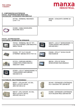
Y203-EN2-02-Katalog.book Seite 249 Mittwoch, 24. Mai 2006 2:22 14 CIMR-G7C Varispeed G7 World first three level inverter architecture • • • • • • • • • • • • • • 3 level control (400 V class) Current vector control and V/F with or without PG Torque control (closed loop and open loop) Silent operation Rotary and stationary autotuning High slip braking function Energy saving function standard LCD operator Embedded OMRON PLC functionality with PLC option card Standard RS-485 communications - Modbus Fieldbus options: DeviceNet, PROFIBUS, CANOpen, LONworks, ethernet PC configuration tool CX-drive and DriveWorksEZ. CE, UL, and cUL marking Customised application software Ratings • 200 V Class three-phase 0.4 to 110 kW • 400 V Class three-phase 0.4 to 300 kW System configuration 3G3IV-PCN329-E Inverter to PC cable CX-Drive DriveWorkEZ JVOP-160 OY Digital operator (LCD display) JVOP-161-OY Digital operator (LED display) Line filter 3G3IV-PCN126/326 Digital operator extension cable Braking accessories Varispeed G7 Monitor option card Feedback speed control card Reference option cards Communication option cards PLC option card U6 JP U10 R70 R11 U8 R28 C28 3 R1 R2 R5 C21 R3 R36 R35 C1 R R6 R8 R120 + U1 R55 R75 R114 C2 R131 U14 R21 R5 R25 R15 R15 R15 1 R54 R56 R57 R40 R39 TR + 2 C5 R20 R30 + C39 C17 R14 R7 C22 C16 R78 R6 D6 C35 R99 R95 Y1 C24 U11 TR 2 11 R11 R11 R10 0 7 C33 U10 U7 1 T1 JP3 C3 + + U9 R11 C26 R52 PE U12 05 R1 R1 R1 0 0 U15 C11 R94 R97 C20 R96 R102 C12 C13 JP5 JP6 R95 RT4 U13 U17 COD E No. SI-N C10 73600 -C021 0 AUDIN - 8, avenue de la malle - 51370 Saint Brice Courcelles - Tel : 03.26.04.20.21 - Fax : 03.26.04.28.20 - Web : http: www.audin.fr - Email : [email protected] Varispeed G7 249 Y203-EN2-02-Katalog.book Seite 250 Mittwoch, 24. Mai 2006 2:22 14 Specifications Type designation CIMR – G7 C 4 0P4 0 Inverter Protective enclosure 0: Open chassis type (IP00) 1: Enclosed type (IP20 / NEMA1) G7 series Specifications C: European standard specifications Max. applicable motor output ~ 0P4: 0.4 kW 022: 22 kW ~ Voltage 2: 200 V class 4: 400 V class 300: 300 kW [ "P" indicates a decimal point ] 200 V class1 Model CIMR-G7C 20P4 20P7 21P5 22P2 23P7 25P5 27P5 2011 2015 2018 2022 Output characteristics Max. applicable motor output2 Inverter capacity 2030 2037 2045 2055 2075 2090 2110 0.4 0.75 1.5 2.2 3.7 5.5 7.5 11 15 18.5 22 30 37 45 55 75 90 110 kVA 1.2 2.3 3.0 4.6 6.9 10 13 19 25 30 37 50 61 70 85 110 140 160 A 3.2 6 8 12 18 27 34 49 66 80 96 130 160 183 224 300 358 415 kW Rated current Max. voltage 3-phase, 200/208/220/230/240 V (proportional to input voltage) Max. output frequency 400 Hz (programmable) Rated input voltage and frequency Allowable voltage fluctuation Allowable frequency fluctuation Harmonic DC reactor wave prevention 12-pulse input Power supply 3-phase 200/208/220/230/240 V, 50/60 Hz3 1. 2. 3. 4. +10%, -15% ±5% Option Provided Not available Available4 The main circuit of 200 V class inverters uses 2-level control method. Standard 4-pole motors are used for max. applicable motor output. Choose the inverter model whose rated current is allowable within the motor rated current range. When using the inverter of 200 V class 30 kW or more with a cooling fan of three-phase 230 V 50 Hz or 240 V 50/60 Hz power supply, a transformer for the cooling fan is required. A 3-wired transformer is required at 12-pulse input. 400 V class1 Model CIMR-G7C Output characteristics Max. applicable motor output2 Inverter capacity Rated current 40P4 40P7 41P5 42P2 43P7 45P5 47P5 4011 4015 4018 4022 4030 4037 4045 4055 4075 4090 4110 4132 4160 4185 4220 4300 kW kVA A 0.4 0.75 1.5 2.2 3.7 5.5 7.5 11 15 18.5 22 30 37 45 55 75 1.4 2.6 3.7 4.7 6.9 11 16 21 26 32 40 50 61 74 98 130 150 180 210 250 280 340 460 1.8 3.4 4.8 6.2 9 15 21 27 34 42 52 65 80 97 128 165 195 240 270 325 370 450 605 Max. voltage 1. 2. 3. 110 132 160 185 220 300 3-phase, 380/400/415/440/460/480 V (proportional to input voltage) 400 Hz (programmable) 3-phase 380/400/415/440/460/480 V, 50/60 Hz Power supply Max. output frequency Rated input voltage and frequency Allowable voltage fluctuation Allowable frequency fluctuation Harmonic DC reactor wave prevention 12-pulse input 90 +10%, -15% ±5% Option Provided Not available Available3 The main circuit of 400 V class inverters uses 3-level control method. Standard 4-pole motors are used for max. applicable motor output. Choose the inverter model whose rated current is allowable within the motor rated current range. A 3-wired transformer is required at 12-pulse input. AUDIN - 8, avenue de la malle - 51370 Saint Brice Courcelles - Tel : 03.26.04.20.21 - Fax : 03.26.04.28.20 - Web : http: www.audin.fr - Email : [email protected] 250 Frequency inverters Y203-EN2-02-Katalog.book Seite 251 Mittwoch, 24. Mai 2006 2:22 14 200 V class Model CIMR-G7C 20P4 20P7 21P5 22P2 23P7 25P5 27P5 2011 2015 2018 2022 2030 2037 2045 2055 2075 2090 2110 Enclosed type Not Available as standard Available for option (IEC IP20) available Open chassis type Available by removing the upper and lower cover of Available as standard (IEC IP00) enclosed type 400 V class Enclosures Model CIMR-G7C 40P4 40P7 41P5 42P2 43P7 45P5 47P5 4011 4015 4018 4022 4030 4037 4045 4055 4075 4090 4110 4132 4160 4185 4220 4300 Enclosed type Available as standard Available for option Not available (IEC IP20) Open chassis type Available by removing the upper and lower cover of Available as standard (IEC IP00) enclosed type Commom specifications Model number CIMR-G7C Control method Torque characteristics Speed control range Control characteristics Closed loop vector control, open loop vector control 1&2, V/f control, V/f with PG control 150% at 0.3 Hz (open loop vector control 2) 150% at 0rpm (closed vector control) 1:200 (open loop vector control 2) 1:1000 (closed loop vector control) ± 0.2% (open loop vector control) ± 0.02% (closed loop vector control) (25 °C ± 10 °C) Speed control response 10 Hz (open loop vector control 2) 30 Hz (control with PG) Provided (4 quadrant steps can be changed by constant settings.) (Vector control) Torque accuracy ± 5% Frequency range 0.01 to 400 Hz Frequency accuracy (temperature characteristics) Frequency setting resolution Output frequency resolution Overload capacity and maximum current Frequency setting signal Digital references: ± 0.01% (-10 °C to +40 °C) Analog references: ± 0.1% (25 °C ±10 °C) Digital references: 0.01 Hz Analog references: 0.025/50 Hz (11 bits plus sign) 0.001 Hz 150% of rated output current for 1 minute 200% of rated output current for 0.5 second 0 to +10 V, -10 to +10 V, 4 to 20 mA, pulse train Accel/decel time 0.01 to 6000.0 s (4 selectable combinations of independent acceleration and deceleration time settings) Braking torque Approximately 20% (Approximately 125% with braking resistor option, braking transistor built into Inverters of 15 kW or less) Main control functions Restarting after momentary power loss, speed search, overtorque/undertorque detection, torque limits, 17-speed control (maximum), 4 acceleration and deceleration times, S-curve acceleration/deceleration, 3-wire control, auto-tuning (rotational or stationary), dwell function, cooling fan ON/OFF control, slip compensation, torque compensation, auto-restart after fault, jump frequencies, upper and lower limits for frequency references, DC braking for starting and stopping, high-slip braking, advanced PID control, energy-saving control, MEMOBUS communications (RS-485/422, 19.2 kbps maximum), 2 motor parameter sets, fault reset and parameter copy function. Motor protection Protection by electronic thermal overload relay. Instantaneous overcurrent protection Stops at approx. 200% of rated output current. Fuse blown protection Protective functions Sine wave PWM Speed control accuracy Torque limits Overload protection Stops for fuse blown. 150% of rated current for 1 minute 200% of rated current for 0.5 second Overvoltage protection 200 Class Inverter: stops when main-circuit DC voltage is above 410 V. 400 Class Inverter: stops when main-circuit DC voltage is above 820 V. Undervoltage protection 200 Class Inverter: stops when main-circuit DC voltage is below 190 V. 400 Class Inverter: stops when main-circuit DC voltage is below 380 V. Momentary power loss ride through Cooling fin overheating Stall prevention Grounding protection Charge indicator Ambient operating temperature Environment Specification Ambient operating humidity Storage temperature Application site Altitude Vibration By selecting the momentary power loss method, operation can be continued if power is restored within 2 s. Protection by thermistor. Stall prevention during acceleration, deceleration and running independently. Protection by electronic circuits. Illuminates when the main circuit DC voltage is approx. 10 VDC or more. -10 °C to 40 °C (enclosed wall-mounted type) -10 °C to 45 °C (open chassis type) 95% max. (with no condensation) - 20 °C to + 60 °C (short-term temperature during transportation) Indoor (no corrosive gas, dust, etc.) 1000 m max. 10 to 20 Hz, 9.8 m/s2 max.; 20 to 50 Hz, 2 m/s2 max AUDIN - 8, avenue de la malle - 51370 Saint Brice Courcelles - Tel : 03.26.04.20.21 - Fax : 03.26.04.28.20 - Web : http: www.audin.fr - Email : [email protected] Varispeed G7 251 Y203-EN2-02-Katalog.book Seite 252 Mittwoch, 24. Mai 2006 2:22 14 Dimensions Open chassis type (IEC IP00) W1 H T1 D1 H2 H1 4-d (5) (5) W (5) D Fig 1 400 V class (3-phase) 200 V class (3-phase) Voltage Max. applicable motor Inverter output kW CIMR-G7C 0.4 ------ 0.75 ------ 1.5 ------ 2.2 ------ 3.7 ------ 5.5 ------ 7.5 ------ 11 2011 15 2015 Fig W H D Dimensions in mm W1 H1 H2 2018 250 400 258 195 385 22 2022 275 450 258 220 435 30 2030 37 2037 375 600 250 575 45 2045 55 2055 450 725 348 325 700 75 2075 500 850 358 370 820 90 2090 110 2110 0.4 ----------- 1.5 ------ 2.2 ------ 4.0 ------ 5.5 ------ 7.5 ------ 11 4011 15 4015 18.5 4018 22 4022 30 4030 37 4037 45 4045 55 4055 75 4075 90 4090 110 4110 132 4132 160 4160 185 4185 220 4220 300 4300 T1 d Approx. weight kg Cooling method Not available please use the IP20 type removing the upper and lower cover 18.5 0.75 D1 1 575 885 298 328 378 7.5 100 855 21 M6 24 57 12.5 445 2.3 3.2 63 M10 86 130 Fan cooled 87 108 15 140 4.5 M12 150 Not available please use the IP20 type removing the upper and lower cover 275 450 258 220 435 325 550 283 260 535 450 725 348 325 700 100 7.5 26 2.3 M6 105 12.5 1 37 3.2 M10 130 500 850 575 916 710 1305 916 1475 358 378 415 370 820 445 855 540 1270 730 1440 90 91 109 15 Fan cooled 127 45.8 140 15 126 165 4.5 M12 175 263 280 415 AUDIN - 8, avenue de la malle - 51370 Saint Brice Courcelles - Tel : 03.26.04.20.21 - Fax : 03.26.04.28.20 - Web : http: www.audin.fr - Email : [email protected] 252 Frequency inverters Y203-EN2-02-Katalog.book Seite 253 Mittwoch, 24. Mai 2006 2:22 14 Enclosed type (IEC IP20) G7C27P51 to G7C20181 G7C20221 to G7C20751 G7C40P41 to G7C45P51 G7C47P51 to G7C40181 G7C40221 to G7C41601 400 V class (3-phase) W (5) H2 H H1 4-d 3 (5) D Inverter CIMR-G7C Fig W H 0.4 20P4 20P7 1.5 21P5 2.2 22P2 3.7 23P7 5.5 25P5 7.5 27P5 11 2011 15 2015 18.5 2018 250 400 22 2022 275 450 30 2030 2037 45 2045 55 2055 75 2075 90 2090 110 2110 0.4 40P4 0.75 40P7 1.5 41P5 2.2 42P2 3.7 43P7 5.5 45P5 7.5 47P5 11 4011 15 4015 18.5 4018 22 4022 30 4030 37 4037 45 4045 55 4055 75 4075 90 4090 110 4110 132 4132 160 4160 185 4185 220 4220 300 4300 (5) Fig 4 D Dimensions in mm W1 H1 H2 157 1 D Fig 3 0.75 37 T1 D1 H10 H3 4 D1 Fig 2 Max. applicable motor output kW 200 V class (3-phase) Voltage H0 H1 W Fig 1 H2 D 3 W1 H3 H0 H D1 W1 T1 T1 4 H2 W 4-d 4-d H1 W1 G7C4185 to G7C4300 H0 H G7C20P41 to G7C25P51 140 280 D1 T1 d 39 126 266 7 177 5 300 197 186 285 240 350 207 216 335 8 375 3 600 298 328 195 385 220 435 250 7 348 325 700 500 850 358 370 820 575 885 378 445 855 280 24 266 3.2 M10 130 300 197 186 285 240 350 207 216 335 275 450 258 220 435 325 550 283 260 535 450 725 348 325 700 63 86 87 108 15 140 7 177 200 Fan cooled 57 4.5 M12 39 126 11 21 12.5 725 140 M6 100 157 1 2.3 7.5 575 450 Self cooled 6 2 258 3 4 65.5 78 Cooling method M5 59 200 Approx. weight kg 8 150 3.5 5 Self cooled M5 59 4.5 65.5 7 78 10 2 3 7.5 100 2.3 M6 105 12.5 37 3.2 M10 130 4 500 850 358 370 820 15 575 916 378 445 855 45.8 710 1305 916 1475 415 540 1270 730 1440 26 Fan cooled 90 91 109 127 140 165 4.5 M12 175 263 15 126 280 415 AUDIN - 8, avenue de la malle - 51370 Saint Brice Courcelles - Tel : 03.26.04.20.21 - Fax : 03.26.04.28.20 - Web : http: www.audin.fr - Email : [email protected] Varispeed G7 253 Y203-EN2-02-Katalog.book Seite 254 Mittwoch, 24. Mai 2006 2:22 14 Filters Footprint / Flat filters Dimensions Model 200 V 400 V 1. 3G3RV-PFI3410-SE 1 A 330 355 408 330 330 355 355 408 386 B 141 206 236 141 141 206 206 236 115 C 46 60 80 46 46 50 50 65 260 D 281 302 355 281 281 302 302 355 306 E 313 336 390 313 313 336 336 390 240 F 115 175 205 115 115 175 175 205 235 G 5.5 6.5 6.5 5.5 5.5 6.5 6.5 6.5 12.0 3G3RV-PFI3600-SE 1 386 135 260 306 240 235 12.0 M12 - - - - 3G3RV-PFI3800-SE 1 564 160 300 516 420 275 9.0 M12 - - - - 3G3RV-PFI2035-SE 3G3RV-PFI2060-SE 3G3RV-PFI2100-SE 3G3RV-PFI3010-SE 3G3RV-PFI3018-SE 3G3RV-PFI3021-SE 3G3RV-PFI3035-SE 3G3RV-PFI3060-SE H M5 M6 M6 M5 M5 M4 M5 M6 M12 I 23 30 40 23 23 25 25 32.5 - J 126 186 216 126 126 186 186 216 - K 266 285 335 266 266 285 285 335 - L M5 M6 M6 M5 M5 M5 M6 M6 - Flat filters are not possible to be mounted as footprint filters. Bookform filters Model 200 V 400 V 3G3RV-PFI2130-SE 3G3RV-PFI2160-SE 3G3RV-PFI2200-SE 3G3RV-PFI3070-SE 3G3RV-PFI3100-SE 3G3RV-PFI3130-SE 3G3RV-PFI3170-SE 3G3RV-PFI3200-SE Dimensions A 366 451 610 331 326 370 451 610 B 180 170 240 185 150 180 170 240 C 90 120 130 80 90 90 120 130 D 280 350 480 300 240 280 350 480 E 310 380 518 329 270 310 380 518 F 65 102 90 55 65 65 102 90 G 6.5 6.5 8.2 6.5 6.5 6.5 6.5 8.3 H M10 M10 M10 M6 M10 M10 M10 M10 AUDIN - 8, avenue de la malle - 51370 Saint Brice Courcelles - Tel : 03.26.04.20.21 - Fax : 03.26.04.28.20 - Web : http: www.audin.fr - Email : [email protected] 254 Frequency inverters Y203-EN2-02-Katalog.book Seite 255 Mittwoch, 24. Mai 2006 2:22 14 Braking unit 12 36.5 Main Circuit Terminal M6 73 150 138 370 350 317 66.5 38 30 or more 30 or more 138.5 3-lead Wire Inlet (20 Dia. Rubber Bush) 104 Lead Wire Inlet (28 Dia. Rubber Bush) 2-lead Wire Inlet (35 Dia. Rubber Bush) 100 59 114.5 128 140 100 or more 38 30 or more 100 or less 72 4-M6 MTG Holes 140 111 156 200 50 140 180 30 or more 100 or less 4-M4 MTG Holes Model CDBR-2110 B 100 or more Model CDBR-2015 B, -2022 B, -4030B, -4045 B Weight 8.5 Kg Weight 1.8 Kg Model CDBR-4220 B 104 Lead Wire Inlet (28 Dia. Rubber Bush) 2-lead Wire Inlet (35 Dia. Rubber Bush) 156.5 118.5 111 156 200 50 30 or more 210 250 100 or more 70 30 or more 100 or more 9 36.5 Main Circuit Terminal M6 370 355 317 4-M6 MTG Holes 210 Weight 12 Kg Braking resistor unit (inverter-mounted type) Note: Prepare mounting screws (2-M4x8 tapped screws). Screws 8mm or more and general metric screws cannot be used. Weight: 0.2 kg Model ERF-150WJ_ 5 182 170 150 13 1.2 44 200 or more Braking resistor unit (separately-installed type) MTG Screw 150 or more 30 or more A 30 or more C 150 50 or more A 50 or more 260 Voltage 220 V class 400 V class Model LKEB-_ 20P7 21P5 22P2 23P7 25P5 25P5 40P7 41P5 42P2 43P7 45P5 47P5 Dimensions in mm A 105 130 130 130 250 250 105 130 130 130 250 250 B 275 350 350 350 350 350 275 350 350 350 350 350 C 50 75 75 75 200 200 50 75 75 75 200 200 D 260 335 335 335 335 335 260 335 335 335 332 332 MTG Screw M5 x 3 M5 x 4 M5 x 4 M5 x 4 M6 x 4 M6 x 4 M5 x 3 M5 x 4 M5 x 4 M5 x 4 M6 x 4 M6 x 4 Weight kg 3.0 4.5 4.5 5.0 7.5 8.5 3.0 4.5 4.5 5.0 7.5 8.5 Voltage 220 V class 400 V class Model LKEB-_ 2011 2015 2018 2022 4011 4015 4018 4022 4030 4037 4045 200 or more C B D B D 150 or more MTG Screw Dimensions in mm A 266 356 446 446 350 350 446 446 356 446 446 B 543 543 543 543 412 412 543 543 956 956 956 C 246 336 426 426 330 330 426 426 336 426 426 D 340 340 340 340 325 325 340 340 740 740 740 MTG Screw M8 x 4 M8 x 4 M8 x 4 M8 x 4 M6 x 4 M6 x 4 M8 x 4 M8 x 4 M8 x 4 M8 x 4 M8 x 4 Weight kg 10 15 19 19 16 18 19 19 25 33 33 AUDIN - 8, avenue de la malle - 51370 Saint Brice Courcelles - Tel : 03.26.04.20.21 - Fax : 03.26.04.28.20 - Web : http: www.audin.fr - Email : [email protected] Varispeed G7 255 Y203-EN2-02-Katalog.book Seite 256 Mittwoch, 24. Mai 2006 2:22 14 Attachments Heatsink external mounting attachment The Varispeed G7 inverters under the 200/400 V class 15 kW or less need this attachment for mounting the heatsink externally. This attachment expands the outer dimensions of the width and height of the inverter. (Attachment is not required for inverters of 18.5 kW or more.) Wall H1 H Mounting panel W1 W D1 D2 D3 or more CIMRG7C 20P4 20P7 21P5 22P2 23P7 25P5 27P5 2011 2015 40P4 40P7 41P5 42P2 43P7 45P5 47P5 4011 4015 Attachment order code W 72616 -EZZ08676A 155 H 302 Dimensions in mm W1 H1 D1 D2 126 D3 37.4 40 57.4 60 290 122.6 72616-EZZ08676B 210 330 180 316 136.1 63.4 70 72616-EZZ08676C 250 392 216 372 133.6 76.4 85 37.4 40 72616-EZZ08676A 155 302 126 290 122.6 57.4 60 72616-EZZ08676B 210 330 180 316 136.1 63.4 70 72616-EZZ08676C 250 392 216 372 133.6 76.4 85 Panel cut for external mounting of cooling fin (heatsink) CIMRG7C 20P4 20P7 21P5 22P2 23P7 25P5 27P5 2011 2015 2018 2022 2030 2037 2045 2055 2075 2090 2100 40P4 40P7 41P5 42P2 43P7 45P5 47P5 4011 4015 4018 4022 4030 4037 4045 4055 4075 4090 4110 4132 4160 4185 4220 4300 Fig W H Dimensions in mm W1 (W2) (W3) H1 (H2) (H3) 155 302 126 6 A B d 8.5 290 9.5 6 138 271 M5 6.5 316 7 197 298 8.5 372 9.5 10 233 353 M6 385 435 8 7.5 244 369 269 419 575 15 1 210 330 180 9 8.5 250 392 216 250 400 195 24.5 275 450 220 3 375 600 250 2 54.5 8 450 725 325 359 545 12.5 700 13.5 M10 434 673 500 850 370 57 8 820 575 885 445 55 10 855 19 15 484 782 155 302 126 6 8.5 290 9.5 6 138 271 M5 6.5 316 7 197 298 250 392 216 8.5 372 9.5 10 233 353 275 450 220 3 555 817 M12 1 210 330 180 9 8.5 435 24.5 269 419 8 325 550 260 M6 7.5 535 309 519 2 450 725 325 54.5 3 500 850 370 57 575 925 445 55 8 700 13.5 12.5 434 673 M10 820 10 19 15 484 782 895 see1 15 555 817 1 4 710 1305 540 76.5 8.5 1270 21.5 see 5 916 1475 730 72.5 20.5 1440 21.5 see1 875 1397 M12 693 1227 1.The sizes are different between the top and the bottom. Refer to figs. 3 to 5 AUDIN - 8, avenue de la malle - 51370 Saint Brice Courcelles - Tel : 03.26.04.20.21 - Fax : 03.26.04.28.20 - Web : http: www.audin.fr - Email : [email protected] 256 Frequency inverters Y203-EN2-02-Katalog.book Seite 257 Mittwoch, 24. Mai 2006 2:22 14 Installation Standard connections DC reactor to improve inputs power factor (optional) U Braking resistor (option) X Short-circuit bar T Main contactor and fuses 2 1 L1 3-phase Power supply L2 200 to 240 V L3 50/60 Hz B1 U/T1 R/L1 Line filter Motor B2 S/L2 V/T2 T/L3 W/T3 Varispeed G7 CIMR-G7C47P5 PE Forward run/stop S1 Reverse run/stop S2 MA MB MC External fault S3 Full reset S4 Multi-step speed setting 1 S5 M2 Multi-step speed setting 2 S6 M3 Jog reference S7 External base Block reference S8 Multi-step speed setting 3 S9 Multi-step speed setting 4 S10 Accel/decel time 1 Emergency stop (NO contact) S11 M1 Multi-function digital inputs [Factory setting] M M4 M5 M6 SC 2 1 -10 to 10 V/ 4 to 20 mA -10 to 10 V P MP AC +V Analog input power supply +15V,, 20 mA -10 to 10 V P P Open collector output 2 [Frequency agreement signal at factory setting] Multi-function open collector output 48 VDC 50mA or less E(G) RP Pulse train input [Default: Frequency reference input] 0 to 32 kHz 2k• 3 Multi-function contact output 250 VAC, 1A or less 30 VDC, 1A or less 24V E(G) 2k• Open collector output 1 [Zero speed signal at factory setting] Open collector output 4 [Frequency (FOUT) detection 2 at factory setting] SN Analog input setting adjustment Run signal at Factory settings Open collector output 3 [Ready to operate at factory setting] S12 SP Fault contact output 250 VAC, 1A or less 30 VDC, 1A or less Analog input 1 Master A1 frequency reference 0 to +10 V (20 k•) FM Multi-functions analog input 2 A2 [Default: Frequency bias 4 to 20 mA (250•)] A2 Multi-functions analog input 3 [Default: Auxiliary Frequency Reference 0 to 10 V (20•)] AM AC AC Pulse train output 0 to 32kHz (2.2 k•) [Output frequency at factory setting] Frequency master adjusting potentiometer 20 k• + Multi-function analog output 1 FM (-10 to +10V, 2mA) [Output frequency af factory Ammeter setting 0 to 10 V] adjusting potentiometer 20 kΩ + Multi-function analog output 2 AM (-10 to +10 V, 2 mA) [Output current at factory o to +10 V] 0V -V Analog input power supply -15 V, 20 mA Terminating resistance R+ P MEMOBUS communication RS-485/422 RS+ P S- IG Shielded cable P Shielded twisted pair cable AUDIN - 8, avenue de la malle - 51370 Saint Brice Courcelles - Tel : 03.26.04.20.21 - Fax : 03.26.04.28.20 - Web : http: www.audin.fr - Email : [email protected] Varispeed G7 257 Y203-EN2-02-Katalog.book Seite 258 Mittwoch, 24. Mai 2006 2:22 14 Main circuit Voltage 200 V 400 V Model CIMR-G7C 20P4 to 2015 2018, 2022 2030 to 2110 40P4 to 4015 4018 to 4045 4055 to 4300 Max. applicable motor output 0.4 to 15 kW 18.5 to 22 kW 30 to 110 kW 0.4 to 15 kW 18.5 to 45 kW 55 to 300 kW R/L1 Main circuit input power supply S/L2 T/L3 R1/L11 S1/L21 Main circuit input power supply Main circuit input power supply R-R1, S-S1 and T-T1 have been wired before shipment (see P59). --- Main circuit input power supply R-R1, S-S1 and T-T1 have been wired before shipment --- T1/L31 U/T1 Inverter output V/T2 Inverter output W/T3 B1 Braking resistor unit B2 •DC reactor ( 1- 2) •DC power supply1 ( 1- ) --- 1 2 3 /l2 Braking resistor unit -----•DC power supply ( 1- 2)1 •Braking unit ( 3- ) ------ •DC reactor ( 1- 2) •DC power supply1 ( 1- ) --- --- ------ 400 / l2 400 Ground terminal (100 Ω or less) 1. 1- •DC power supply ( 1- 2)1 •Braking unit ( 3- ) --- Cooling fan power supply2 r/l1 200 / l2 200 ------ Cooling fan power supply3 Ground terminal (10 Ω or less) DC power input does not conform to UL/c-UL listed standard. 2. Cooling fan power supply r/l1- /l2: 200 to 220 VAC 50 Hz, 200 to 230 VAC 60 Hz (A transformer is required for 230 V 50 Hz or 240 V 50/60 Hz power supply.) 3. Cooling fan power supply r/l1 - 200 / l2 200: 200 to 220 VAC 50 Hz, 200 to 230 VAC 60 Hz, r/l1 - 400 / l2 400: 380 to 480 VAC 50/60 Hz Main circuit configuration CIMR-G7C2018, 2022 CIMR-G7C40P4 to 4015 CIMR-G7C4018 to 4045 CIMR-G7C2030 to 2110 200V class CIMR-G7C20P4 to 2015 400V class CIMR-G7C4055 to 4300 1. For 200 V class filters, consult with standard OMRON supplier. AUDIN - 8, avenue de la malle - 51370 Saint Brice Courcelles - Tel : 03.26.04.20.21 - Fax : 03.26.04.28.20 - Web : http: www.audin.fr - Email : [email protected] 258 Frequency inverters Y203-EN2-02-Katalog.book Seite 259 Mittwoch, 24. Mai 2006 2:22 14 Control circuit Analog input Sequence input Type No. Signal name S1 S2 S3 S4 Forward run/stop signal Reverse run/stop signal Multi-function input selection 1 Multi-function input selection 2 S5 Multi-function input selection 3 S6 Multi-function input selection 4 S7 S8 Multi-function input selection 5 Multi-function input selection 6 S9 Multi-function input selection 7 S10 Multi-function input selection 8 S11 Multi-function input selection 9 S12 Multi-function input selection 10 SC Sequence control input common +V +15 V power supply output –V –15 V power supply output A1 Master speed frequency reference A2 Multi-function analog input A3 AC E(G) RS-485/422 Pulse I/O Analog monitor output Relay output Photo-coupler output P1 P2 PC Master speed frequency reference Analog common Connection to shield wire and option ground wire Multi-function PHC output 1 Multi-function PHC output 2 Function – – Multi-function PHC output 3 Factory setting: ready to operate (READY). Multi-function PHC output 4 Factory setting: frequency (FOUT) detection 2 MA Fault output (NO contact) Fault at “closed” between terminals MA and MC MB MC M1 M2 FM Fault output (NC contact) Rely contact output common Multi-function contact output (NO contact) Multi-function analog monitor 1 AM Multi-function analog monitor 2 AC RP MP R+ RS+ SIG Analog common Multi-function pulse input Multi-function pulse monitor Fault at “open” between terminals MB and MC – Factory setting: run signal Running at “closed” between terminals M1 and M2 Factory setting: output frequency 0 to 10 V/100% freq. Factory setting: current monitor 5 V / inverter rated current – Factory setting: frequency reference input (H6-01=0) Factory setting: output frequency (H6-06=2) C3 P4 C4 MEMOBUS communications input MEMOBUS communications output Signal common – Factory setting: zero speed signal “Closed” at or below zero speed level (b2-01) Factory setting: frequency agreement “Closed” within ±2Hz of setting frequency Photo-coupler output common P3 Signal level Forward run at “closed”, stop at “open” Reverse run at “closed”, stop at “open” Factory setting: external fault at “closed” Factory setting: fault reset at “closed” Factory setting: multi-step speed setting 1 is valid at “closed” Factory setting: multi-step speed setting 2 is valid at “closed” Factory setting: JOG run at “closed” Photo-coupler input +24 VDC Factory setting: external baseblock at “closed” 8 mA isolation Factory setting: multi-step speed setting 3 is valid at “closed” Factory setting: multi-step speed setting 4 is valid at “closed” Factory setting: accel/decel time setting 1 is valid at “closed” Factory setting: emergency stop (NO contact) is valid at “closed” – +15 V (allowable current For analog reference +15 V power supply 20 mA max.) -15 V (allowable current For analog reference -15 V power supply 20 mA max.) -10 to +10 V, 0 to +10V -10 to +10 V/ -100 to +100%, 0 to +10 V/ 100% (input impedance 20 k) 4 to 20 mA/100%, -10 to +10 V/ -100 to +100%, 4 to 20 mA 0 to +10 V/ 100% (input impedance 250 Ω) Factory setting: added to the terminal A1 (H3-09=0) -10 to +10 V/ -100 to +100%, 0 to +10 V/ 100% 0 to +10 V Factory setting: preset frequency reference (input impedance 20 kΩ) 0V – For 2-wire RS-485, short R+ and S+ as well as R- and S-. – +48 VDC 50 mA or less Dry contact, contact capacity 250 VAC 1 A or less 30 VDC 1 A or less 0 to +10 VDC ±5% 2 mA or less 0 to 32 kHz (3 kΩ) 0 to 32 kHz (2.2 kΩ) Differential input, photocoupler isolation Differential input, photocoupler isolation – AUDIN - 8, avenue de la malle - 51370 Saint Brice Courcelles - Tel : 03.26.04.20.21 - Fax : 03.26.04.28.20 - Web : http: www.audin.fr - Email : [email protected] Varispeed G7 259 Y203-EN2-02-Katalog.book Seite 260 Mittwoch, 24. Mai 2006 2:22 14 Remove the upper and lower covers for the models of 15 kW or less in 200 V and 400 V classes. When using open chassis type inverters of 200 V/400 V 22 kW or more, secure spaces for eyebolts and wiring of the main circuit. Upper cover Internal heatsink Upper cover 55 ˚C 50 mm or more 120 mm or more Air Upper part air temperature -10 to 55 ˚C Heatsink Heatsink Open chassis type inverter Lower cover Inverter inlet temperature -10 to 45 ˚C 45 ˚C 30 mm or more 50 mm or more Peripheral temperature 40 ˚C Lower cover 30 mm or more 120 mm or more Air Side spaces Top and bottom spaces Cover MTG screw Inverter heat loss 200 V class Heat loss W Model CIMR-G7C 20P4 Inverter capacity kVA 1.2 A 3.2 Rated current 20P7 2.3 21P5 3.0 22P2 4.6 23P7 6.9 25P5 10 27P5 13 2011 19 2015 25 2018 30 2022 37 2030 50 2037 61 2045 70 2055 85 2075 110 2090 140 2110 160 6 8 12 18 27 34 49 66 80 96 130 160 183 224 300 358 415 Fin W 21 43 58 83 122 187 263 357 473 599 679 878 1080 1291 1474 2009 1660 2389 Inside unit W 36 42 47 53 64 87 112 136 174 242 257 362 434 510 607 823 871 1194 Total heat loss W 57 85 105 136 186 274 375 493 647 839 936 1240 1514 1801 2081 2832 2531 3583 Self cooled Fin coding Fan cooled 400 V class Model CIMR-G7C Inverter capacity 40P4 40P7 41P5 42P2 43P7 45P5 47P5 4011 4015 4018 4022 4030 4037 4045 4055 4075 4090 4110 4132 4160 4185 4220 4300 1.4 2.6 3.7 4.7 6.9 11 16 21 26 32 40 50 61 74 98 130 150 180 194 230 280 340 460 A 1.8 3.4 4.8 6.2 9 15 21 27 34 42 52 65 80 97 Fin W 10 21 33 41 76 132 198 246 311 354 516 633 737 929 1239 1554 1928 2299 2612 3614 4436 5329 6749 Inside unit W 39 44 46 49 64 79 106 116 135 174 210 246 285 340 Total heat loss W 49 65 79 90 140 211 304 362 446 528 726 879 1022 1269 1727 2150 2690 3227 3717 5115 6430 7534 9690 Rated current Heat loss W kVA Self cooled Fin coding 128 488 165 596 240 762 255 302 370 450 605 928 1105 1501 1994 2205 2941 Fan cooled Connections for braking units Connections for braking resistors P B Braking resistor Braking resistor overload relay trip contact (thermal relay trip contact) 1 3 MCCB MC 3-phase R S Power Supply T 195 R B1 T 2 Motor Varispeed G7 P U V 1 2 Braking Resistor Unit B2 S Braking resistor overload relay trip contact (thermal relay trip contact) Braking resistor unit *3 B P B IM · Set constant L8-01 to 1 (mounting type braking resistor protection enabled). Level detector W Varispeed G7 MASTER MASTER SLAVE SLAVE +15 5 1 1 Braking unit 2*2 P · Set sequence to shutt off the power side at inverter fault contact output. 6 2 Braking unit 1 3 4 Cooling fin overheat contact (Thermoswitch contact) 2 3 4 Cooling fin overheat contact (Thermoswitch contact) AUDIN - 8, avenue de la malle - 51370 Saint Brice Courcelles - Tel : 03.26.04.20.21 - Fax : 03.26.04.28.20 - Web : http: www.audin.fr - Email : [email protected] 260 Frequency inverters Y203-EN2-02-Katalog.book Seite 261 Mittwoch, 24. Mai 2006 2:22 14 AC reactor Application example Connection example Power supply capacity (kVA) AC reactor MCCB Motor AC reactor required for power supply harmonics Varispeed G7 AC reactor not required Inverter capacity (kVA) Max. applicable motor output kW 0.4 0.75 1.5 2.2 3.7 5.5 7.5 11 15 18.5 22 30 37 45 55 75 90 110 200 V Class Current value A 2.5 5 10 15 20 30 40 60 80 90 120 160 200 240 280 360 500 500 Inductance mH 4.2 2.1 1.1 0.71 0.53 0.35 0.265 0.18 0.13 0.12 0.09 0.07 0.05 0.044 0.038 0.026 0.02 0.02 Max. applicable motor output kW 0.4 0.75 1.5 2.2 3.7 5.5 7.5 11 15 18.5 22 30 37 45 55 75 90/110 132/160 185 220 300 400 V class Current value A 1.3 2.5 5 7.5 10 15 20 30 40 50 60 80 90 120 150 200 250 330 Inductance mH 18.0 8.4 4.2 3.6 2.2 1.42 1.06 0.7 0.53 0.42 0.36 0.26 0.24 0.18 0.15 0.11 0.09 0.06 490 0.04 660 0.03 DC reactor DC reactor MCCB ⊕ ⊕ Motor Varispeed G7 Power supply capacity (kVA) Take off the common bar between G1 and G2, and wire as shown in the diagram. With reactor for power supply coordination Inverter capacity (kVA) 200 V class Max. applicable motor output kW 0.4 0.75 400 V class Current value A Inductance mH 5.4 8 18 3 1.5 2.2 Max. applicable motor output kW 0.4 0.75 1.5 2.2 3.7 3.7 5.5 5.5 7.5 11 15 18.5 22 to 110 Without reactor 36 1 72 0.5 90 0.4 Built-in 7.5 11 15 18.5 22 to 300 Current value A Inductance mH 3.2 28 5.7 11 12 6.3 23 3.6 33 1.9 47 1.3 Built-in AUDIN - 8, avenue de la malle - 51370 Saint Brice Courcelles - Tel : 03.26.04.20.21 - Fax : 03.26.04.28.20 - Web : http: www.audin.fr - Email : [email protected] Varispeed G7 261 Y203-EN2-02-Katalog.book Seite 262 Mittwoch, 24. Mai 2006 2:22 14 Fuse installation To protect the inverter, it is recommended to use semiconductor fuses as shown in the table below Inverter type FUSE Voltage (V) Current (A) I2t (A2s) 20P4 20P7 21P5 22P2 23P7 25P5 27P5 2011 2015 2018 2022 2030 2037 2045 2055 2075 2090 2110 240 240 240 240 240 240 240 240 240 240 240 240 240 240 240 240 240 240 10 15 20 30 40 60 80 100 130 150 180 240 300 350 450 550 600 700 12~25 23~55 34~98 82~220 220~610 290~1300 450~5000 1200~7200 1800~7200 870~16200 1500~23000 2100~19000 2700~55000 4000~55000 7100~64000 11000~64000 13000~83000 13000~83000 40P4 40P7 41P5 42P2 43P7 44P0 45P5 47P5 4011 4015 4018 4022 4030 4037 4045 4055 4075 4090 4110 4132 4160 4185 4220 4300 480 480 480 480 480 480 480 480 480 480 480 480 480 480 480 480 480 480 480 480 480 480 480 480 5 10 10 15 20 25 30 40 50 60 70 90 110 140 160 220 300 330 400 450 540 750 750 1000 16~660 19~660 46~660 78~660 110~660 220~660 240~900 320~900 1000~18000 1500~4100 530~5800 1130~5800 1700~5800 2000~13000 3000~13000 6800~55000 3800~55000 12000~23000 18000~64000 28000~25000 40000~250000 63000~400000 63000~400000 94000~920000 AUDIN - 8, avenue de la malle - 51370 Saint Brice Courcelles - Tel : 03.26.04.20.21 - Fax : 03.26.04.28.20 - Web : http: www.audin.fr - Email : [email protected] 262 Frequency inverters Y203-EN2-02-Katalog.book Seite 263 Mittwoch, 24. Mai 2006 2:22 14 Ordering information 3G3IV-PCN329-E Inverter to PC cable G CX-Drive DriveWorkEZ G JVOP-160 OY Digital operator (LCD display) JVOP-161-OY Digital operator (LED display) 3G3IV-PCN126/326 Digital operator extension cable G G G Line filter Braking accessories Varispeed G7 A H Feedback speed control card Monitor option card Reference option cards Communication option cards PLC option card T1 JP3 JP 1 U10 R5 C21 R3 R36 R35 R1 R2 R70 R11 U8 R28 C28 R8 R120 + U1 R55 R75 R114 C2 U14 R21 R5 R25 R15 R15 R15 1 R54 R56 R57 R40 R39 TR + 2 C5 R20 R30 + C39 C17 R14 R7 R131 R78 R6 D6 C35 R99 R95 Y1 C22 C16 3 U10 U7 C1 R R6 C24 U11 TR 2 11 R11 R11 R10 0 7 C33 U6 C3 + + U9 R11 C26 R52 PE U12 R1 05 R1 R1 0 0 U15 C11 R94 R97 C20 R96 R102 C12 C13 JP5 JP6 R95 B C RT4 D U13 U17 COD E No. SI-N C10 73600 -C021 0 E F Varispeed G7 200 V 400 V Inverter Model Varispeed G7 Line Filters Inverter Model EN55011 Class B, 25 m A, 100 m Current (A) 10 B, 25 m A, 100 m B, 25 m A, 100 m 18 1.3 35 1.4 3G3RV-PFI2060-SE B, 25 m A, 100 m 60 3 CIMR-G7C40P4 CIMR-G7C40P7 CIMR-G7C41P5 CIMR-G7C42P2 CIMR-G7C43P7 CIMR-G7C44P0 CIMR-G7C45P5 3G3RV-PFI2100-SE B, 25 m A, 100 m 100 4.9 CIMR-G7C47P5 Type CIMR-G7C20P4 CIMR-G7C20P7 CIMR-G7C21P5 3G3RV-PFI3010-SE CIMR-G7C22P2 CIMR-G7C23P7 CIMR-G7C25P5 CIMR-G7C27P5 CIMR-G7C2011 CIMR-G7C2015 CIMR-G7C2018 CIMR-G7C2022 CIMR-G7C2030 CIMR-G7C2037 CIMR-G7C2045 CIMR-G7C2055 CIMR-G7C2075 CIMR-G7C2090 CIMR-G7C2110 3G3RV-PFI2035-SE 3G3RV-PFI3018-SE Weight (kg) 1.2 3G3RV-PFI2130-SE 3G3RV-PFI2160-SE 3G3RV-PFI2200-SE A, 100 m A, 100 m A, 100 m 130 160 200 4.3 6.0 11.0 3G3RV-PFI3410-SE A, 100 m 400 8.6 3G3RV-PFI3600-SE A, 100 m 600 11.0 Varispeed G7 CIMR-G7C4011 CIMR-G7C4015 CIMR-G7C4018 CIMR-G7C4022 CIMR-G7C4030 CIMR-G7C4037 CIMR-G7C4045 CIMR-G7C4055 CIMR-G7C4075 CIMR-G7C4090 CIMR-G7C4110 CIMR-G7C4132 CIMR-G7C4160 CIMR-G7C4185 CIMR-G7C4220 CIMR-G7C4300 Line Filters Type EN55011 Class Current (A) Weight (kg) 3G3RV-PFI3010-SE B, 25 m A, 100 m 10 1.2 3G3RV-PFI3018-SE B, 25 m A, 100 m 18 1.3 21 1.8 35 2.2 60 4.0 3G3RV-PFI3021-SE 3G3RV-PFI3035-SE 3G3RV-PFI3060-SE B, 25 m A, 100 m B, 25 m A, 100 m B, 25 m A, 100 m 3G3RV-PFI3070-SE B, 25 m A, 100 m 70 3.4 3G3RV-PFI3100-SE A, 100 m 100 4.5 3G3RV-PFI3130-SE 3G3RV-PFI3170-SE 3G3RV-PFI3200-SE A, 100 m A, 100 m A, 100 m 130 170 250 4.7 6.0 11 3G3RV-PFI3410-SE A, 100 m 400 8.6 3G3RV-PFI3600-SE A, 100 m 600 11 3G3RV-PFI3800-SE A, 100 m 800 31.0 AUDIN - 8, avenue de la malle - 51370 Saint Brice Courcelles - Tel : 03.26.04.20.21 - Fax : 03.26.04.28.20 - Web : http: www.audin.fr - Email : [email protected] Varispeed G7 263 Y203-EN2-02-Katalog.book Seite 264 Mittwoch, 24. Mai 2006 2:22 14 A Line filters 200 V 400 V Inverter model Varispeed G7 Line filters Type CIMR-G7C20P4 CIMR-G7C20P7 3G3RV-PFI3010-SE CIMR-G7C21P5 3G3RV-PFI3018-SE CIMR-G7C22P2 CIMR-G7C23P7 CIMR-G7C25P5 CIMR-G7C27P5 CIMR-G7C2011 CIMR-G7C2015 CIMR-G7C2018 CIMR-G7C2022 CIMR-G7C2030 CIMR-G7C2037 CIMR-G7C2045 CIMR-G7C2055 CIMR-G7C2075 CIMR-G7C2090 CIMR-G7C2110 3G3RV-PFI2035-SE EN55011 class B, 25 m A, 100 m B, 25 m A, 100 m B, 25 m A, 100 m Current (A) Weight (kg) 10 1.2 18 1.3 35 1.4 3G3RV-PFI2060-SE B, 25 m A, 100 m 60 3 3G3RV-PFI2100-SE B, 25 m A, 100 m 100 4.9 3G3RV-PFI2130-SE 3G3RV-PFI2160-SE A, 100 m A, 100 m 130 160 4.3 6.0 3G3RV-PFI2200-SE A, 100 m 200 11.0 3G3RV-PFI3410-SE A, 100 m 400 8.6 3G3RV-PFI3600-SE A, 100 m 600 11.0 Inverter model Varispeed G7 CIMR-G7C40P4 CIMR-G7C40P7 CIMR-G7C41P5 CIMR-G7C42P2 CIMR-G7C43P7 CIMR-G7C44P0 Line filters Model Current (A) Weight (kg) 3G3RV-PFI3010-SE B, 25 m A, 100 m 10 1.2 3G3RV-PFI3018-SE B, 25 m A, 100 m 18 1.3 21 1.8 35 2.2 CIMR-G7C45P5 3G3RV-PFI3021-SE CIMR-G7C47P5 3G3RV-PFI3035-SE CIMR-G7C4011 CIMR-G7C4015 CIMR-G7C4018 CIMR-G7C4022 CIMR-G7C4030 CIMR-G7C4037 CIMR-G7C4045 CIMR-G7C4055 CIMR-G7C4075 CIMR-G7C4090 CIMR-G7C4110 CIMR-G7C4132 CIMR-G7C4160 CIMR-G7C4185 CIMR-G7C4220 CIMR-G7C4300 EN 55011 class B, 25 m A, 100 m B, 25 m A, 100 m B, 25 m A, 100 m 60 4.0 3G3RV-PFI3070-SE B, 25 m A, 100 m 70 3.4 3G3RV-PFI3100-SE A, 100 m 100 4.5 3G3RV-PFI3130-SE 3G3RV-PFI3170-SE 3G3RV-PFI3200-SE A, 100 m A, 100 m A, 100 m 130 170 250 4.7 6.0 11 3G3RV-PFI3410-SE A, 100 m 400 8.6 3G3RV-PFI3600-SE A, 100 m 600 11.0 3G3RV-PFI3800-SE A, 100 m 800 31.0 3G3RV-PFI3060-SE B Monitor option cards Monitor option card Type Model AO-08 / 3G3IV-PAO08 AO-12 / 3G3IV-PAO12 Description Analog monitor card DO-08 / 3G3IV-PDO08 Digital output card DO-02C / 3G3IV-PDO02C 2C-relay output card Function • Outputs analog signal for monitoring inverter output state (output freq., output current etc.) after absolute value conversion. • Output resolution: 8 bits (1/256) • Output voltage: 0 to {10 V (non isolated) EOutput channel: 2 channels • Outputs analog signal for monitoring inverter output state (output freq., output current etc.) • Output resolution: 11 bits (1/2048) + code • Output voltage: |10 to {10 V (non isolated) EOutput channel: 2 channels • Outputs isolated type digital signal for monitoring inverter run state (alarm signal, zero speed detection etc.) . • Output channel: photo coupler 6 channels (48 V, 50 mA or less) Relay contact output 2 channels (250 VAC, 1 A or less 30 VDC, 1 A or less) • Two multi-function contact outputs (2C-relay) can be used other than those of the inverter proper unit. AUDIN - 8, avenue de la malle - 51370 Saint Brice Courcelles - Tel : 03.26.04.20.21 - Fax : 03.26.04.28.20 - Web : http: www.audin.fr - Email : [email protected] 264 Frequency inverters Y203-EN2-02-Katalog.book Seite 265 Mittwoch, 24. Mai 2006 2:22 14 Type Model PG-A2 / 3G3FV-PPGA2 Feedback speed control card C Feedback speed control cards PG-B2 / 3G3FV-PPGB2 PG-D2 / 3G3FV-PPGD2 Description Function • Phase A pulse (single pulse) inputs (voltage, complementary, open collector input) • PG frequency range: Approx. 30 kHz max. [Power supply output for PG: +12 V, max. current 200 mA] • Pulse monitor output: +12 V, 20 mA • Phase A and B pulse inputs (exclusively for complementary input) • PG frequency range: Approx. 30 kHz max. [Power supply output for PG: +12 V, Max. current 200 mA] • Pulse monitor output: Open collector, +24 V, Max. current 30 mA PG speed controller card (used for V/f control with PG or • Phase A pulse (differential pulse) input for V/f control (RS-422 input) flux vector) • PG frequency range: Approx. 300 kHz max. [Power supply output for PG: +5 V or +12 V, Max. current 200 mA] • Pulse monitor output: RS-422 PG-X2 / 3G3FV-PPGX2 • Phase A, B and Z pulse (differential pulse) inputs (RS-422 input) • PG frequency range: Approx. 300 kHz max. [Power supply output for PG: +5 V or +12 V, Max. current 200 mA] • Pulse monitor output: RS-422 D Communication option cards Model Communication option card Type 1. Description SI-N1 DeviceNet option card SI-P1 PROFIBUS-DP option card SI-S1 CANopen option card SI-J LONWORKS option card SI-T MECHATROLINK-II option board CM090 Ethernet option card Function • Used for running or stopping the inverter, setting or referencing parameters, and monitoring output frequency, output current, or similar items through DeviceNet communication with the host controller. • Used for running or stopping the inverter, setting or referencing parameters, and monitoring output frequency, output current, or similar items through PROFIBUS-DP communication with the host controller. • Used for running or stopping the inverter, setting or referencing parameters, and monitoring output frequency, output current, or similar items through CANopen communication with the host controller. • Used for HVAC control, running or stopping the inverter, setting or referencing parameters, and monitoring output current, watt-hours, or similar items through LONWORKS communications with peripheral devices. • High speed motion bus • Used for running or stopping the inverter, setting or referencing parameters, and monitoring output frequency, output current, or similar items through MECHATROLINK-II communication with the host controller. • Host contoller: Trajexia, MCH and MP series 1 • Modbus TCP/IP ethernet interface unit Please refer to Trajexia, MCH or MP series for host controllers detailed information. E Reference option cards Reference option card Type Model Description AI-14U / 3G3IV-PAI14U Analog input card AI-14B / 3G3IV-PAI14B DI-08 / 3G3IV-PDI08 DI-16H2 / 3G3IV-PDI16H2 Digital reference card Function • 2 channel high resolution analog input card • Channel 1: 0 to 10 V (20 KΩ) • Channel 2: 4 to 20 mA (250 Ω) • Resolution 14 bit • 3 Channel high resolution analog input card • Signal level: -10 to +10 V (20 KΩ) • 4 to 20 mA (250 Ω) •Resolution: 13 bit + sign • 8 bit digital speed reference input card • 16 bit digital speed reference input card F PLC option boards Type Model 3G3RV-P10ST8-E Description PLC option PLC option Function • Full PLC features, wireless installation and seamless access to the inverter parameters and analogue/digital inputs and outputs. • Embedded Compubus/S fieldbus • Standard OMRON tools can be used for programming • Same features as standard models with DeviceNet support. PLC option with DeviceNet 3G3RV-P10ST8-DRT-E AUDIN - 8, avenue de la malle - 51370 Saint Brice Courcelles - Tel : 03.26.04.20.21 - Fax : 03.26.04.28.20 - Web : http: www.audin.fr - Email : [email protected] Varispeed G7 265 Y203-EN2-02-Katalog.book Seite 266 Mittwoch, 24. Mai 2006 2:22 14 G Accessories Type Model JVOP-160-OY Description Installation Panel cutout 57 70 44 Through Hole 20 14.5 2.5 JVOP-161-OY Panel 2-M3 MTG Holes 120 111 120 Digital operator 5 lines LCD digital operator 7 language support 70 15.8 6.4 7 segment LED digital operator (60) Accessories Panel cutout installation 3G3IV-PCN126 3G3IV-PCN326 Digital operator extension cable 1 meter 3 meters ----- 3G3IV-PCN329-E PC configuration cable ----- G Accessories Software Type Model CX-drive 1.1 Description Computer software Function Configuration and monitoring software tool for drives (Version 1.1 or higher) DriveWorksEZ Computer software Programming special functionality software tool for drives CX-One Computer software Complete automation software including CX-drive. AUDIN - 8, avenue de la malle - 51370 Saint Brice Courcelles - Tel : 03.26.04.20.21 - Fax : 03.26.04.28.20 - Web : http: www.audin.fr - Email : [email protected] 266 Frequency inverters Y203-EN2-02-Katalog.book Seite 267 Mittwoch, 24. Mai 2006 2:22 14 H Braking unit, braking resistor unit Braking resistor unit1 Separately-installed type (10 %ED, 10 sec. max.)3 Braking unit Inverter-mounted type (3 %ED, 10 sec max)2 Inverter Voltage 200 V class 400 V class 1. 2. 3. 4. 5. Max. applicable motor output kW 0.4 0.75 1.5 2.2 3.7 5.5 7.5 11 15 18.5 22 30 37 45 55 75 90 110 0.4 0.75 1.5 2.2 3.7 4.0 5.5 7.5 11 15 18.5 22 30 37 45 55 75 90 110 132 160 185 220 300 Model CIMRG7C_ 20P4 20P7 21P5 22P2 23P7 25P5 27P5 2011 2015 2018 2022 2030 2037 2045 2055 2075 2090 2110 40P4 40P7 41P5 42P2 43P7 44P0 45P5 47P5 4011 4015 4018 4022 4030 4037 4045 4055 4075 4090 4110 4132 4160 4185 4220 4300 Model No. of Model Resis- No. of CDBR_ used ERF-150WJ_ tance Used 201 201 101 700 620 Built-in 2022B 2015B 2015B 2022B 2022B 2110B 2110B 2110B 1 2 2 2 2 1 1 1 Built in 4030B 4030B 4045B 4045B 4030B 4045B 4220B 4220B 4220B 4220B 4220B 4220B 4220B 1 1 1 1 2 2 1 1 1 1 1 1 2 200 Ω 200 Ω 100 Ω 70 Ω 62 Ω 1 1 1 1 1 Braking torque % Model LKEB_ 220 125 125 120 100 70 W 70 W 260 W 260 W 390 W 520 W 780 W 2400 W 3000 W 3000 W 4800 W 3000 W 3000 W 4800 W 4800 W 4800 W 4800 W 4800 W 70 W 70 W 260 W 260 W 200 Ω 200 Ω 100 Ω 70 Ω 40 Ω 30 Ω 20 Ω 13.6 Ω 10 Ω 10 Ω 6.8 Ω 10 Ω 10 Ω 6.8 Ω 6.8 Ω 6.8 Ω 6.8 Ω 8Ω 750 Ω 750 Ω 400 Ω 250 Ω 1 1 1 1 1 1 1 1 1 1 1 2 2 2 2 3 4 5 1 1 1 1 220 125 125 120 125 115 125 125 125 125 125 125 100 120 100 110 120 100 230 130 125 135 Connectable min resistance value Ω 48 48 48 16 16 16 9.6 9.6 9.6 9.6 6.4 9.6 9.6 6.4 6.4 1.6 1.6 1.6 96 96 64 64 Specifications No. of of resistor Used Braking torque % 751 751 401 301 750 Ω 750 Ω 400 Ω 300 Ω 1 1 1 1 230 130 125 115 20P7 20P7 21P5 22P2 23P7 25P5 27P5 2011 2015 2015 2022 2015 2015 2022 2022 2022 2022 2018 40P7 40P7 41P5 42P2 201 200 Ω 1 110 43P7 390 W 150 Ω 1 135 32 45P5 47P5 4011 4015 4018 4022 4030 4037 4045 4030 4045 4030 4030 4045 4045 4045 4037 4045 520 W 780 W 1040 W 1560 W 4800 W 4800 W 6000 W 9600 W 9600 W 6000 W 9600 W 6000 W 6000 W 9600 W 9600 W 9600 W 9600 W 9600 W 100 Ω 75 Ω 50 Ω 40 Ω 32 Ω 27.2 Ω 20 Ω 16 Ω 13.6 Ω 20 Ω 13.6 Ω 20 Ω 20 Ω 13.6 Ω 13.6 Ω 13.6 Ω 16 Ω 13.6 Ω 1 1 1 1 1 1 1 1 1 2 2 3 3 4 4 4 5 6 135 130 135 125 125 125 125 125 125 135 145 100 100 140 140 120 110 110 32 32 20 20 19.2 19.2 19.2 12.8 12.8 19.2 12.8 3.2 3.2 3.2 3.2 3.2 3.2 3.2 --- --- --- --- When connecting a mounting type resistor or braking resistor unit, set system constant L3-04 to 0 (stall prevention disabled during deceleration). If operating without changing the constant, motor does not stop at set deceleration time. When connecting mounting type braking resistor, set system constant L8-01 to 1 (braking resistor protection enabled). Load factor during deceleration to stop a load with constant torque. With constant output or continuous regenerative braking, the load factor is smaller than the specified value. Resistance value per one braking unit. Select a resistance value that is larger than connectable minimum resistance value to obtain enough braking torque. For an application with large regenerative power such as hoisting, the braking torque or other items may exceed the capacity of a braking unit with a braking resistor in a standard combination (can result in capacity overload). Contact your OMRON representatives when the braking torque or any other item exceeds the values in the table. AUDIN - 8, avenue de la malle - 51370 Saint Brice Courcelles - Tel : 03.26.04.20.21 - Fax : 03.26.04.28.20 - Web : http: www.audin.fr - Email : [email protected] Varispeed G7 267 Y203-EN2-02-Katalog.book Seite 268 Mittwoch, 24. Mai 2006 2:22 14 ALL DIMENSIONS SHOWN ARE IN MILLIMETERS. To convert millimeters into inches, multiply by 0.03937. To convert grams into ounces, multiply by 0.03527. In the interest of product improvement, specifications are subject to change without notice. Cat. No. I37E-EN-01A AUDIN - 8, avenue de la malle - 51370 Saint Brice Courcelles - Tel : 03.26.04.20.21 - Fax : 03.26.04.28.20 - Web : http: www.audin.fr - Email : [email protected] 268 Frequency inverters
© Copyright 2026