
GLOBE CONTROL VALVE - Valtek Sulamericana MENA Valves
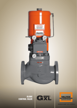
GLOBE CONTROL VALVE GL H VALTEK SULAMERICANA MIDDLE EAST & N. AFRICA GL MIDDLE H GLOBE CONTROL EAST & VALVE N. AFRICA 1 I N T R O D U C T I O N The GL H globe control valve was designed primarily for critical, high-pressure applications for the oil and gas, power and process industries. The GLH Series was developed as an extension to the renowned GLS control valve made by Valtek Sulamericana, having similar advanced characteristics such as a self-centering seat, double upper guide system, top entry assembly and spring-cylinder actuators, among other features. The clamped-in seat ring, secured by the seat retainer, as well as all other components of the valve and the actuator, do not require any special tools for removal. The plug, is not guided by the seat retainer thus increasing trim service life. Manufactured in sizes from 1 to 24 inches and ANSI 900, 1500 and 2500 pressure classes, the GLH Series is available with several body and trim configurations, including special versions for severe service conditions. The GLH Series is developed with the concept of interchangeability of parts that are extremlly easy to maintain, which in turn translate into reduced operating costs. The GLH Series uses a double-acting cylinder and piston type actuators, to achieve the required failsafe position, providing high pneumatic stiffness, excellent positioning in throttling control, fast and reliable response to changes in the control signal. Operating with an air supply pressure of up to 150 psi (10.3 Bar), the actuators of the GLH Series provide more than sufficient force to achieve the desired tightness, even in cases when the valve experiences very high differential pressures. Valtek Sulamericana offers a wide range of positioners, complete with high performance anti-cavitation/noise attenuation trim, making the GLH Series one of the most trusted and relied upon control valve for high pressure and severe service applications worldwide. 2 GL H GLOBE CONTROL VALVE GLH SERIES – BODY SUB-ASSEMBLY (FIGURE 1) Top Entry Assembly: Quick and Easy Maintenance PT Packing for Fugitive Emissions Control Supplied as Standard with optional live loading Self-Centering Seat: Excellent Shutoff Ability; No Special Tools Required Double Upper Guide System: Out of Flow Passage- Rangeability 30:1 (Typical) ANSI Class Shutoff IV — Metal Seat* ANSI Class VI Shutoff — Soft Seat* * Standard for valves with unbalanced trim. VALTEK SULAMERICANA MIDDLE EAST & N. AFRICA B O D Y F O R M S Conventional Globe-style Body The GLH Series globe-style body (fig.1) features a streamlined and smooth passageway. The internal passage of the valve body is designed to maintain a nearly constant area with no pockets, allowing high capacity flows with minimum turbulence. The GLH Series valve bodies are engineered anddesigned to maintain uniform wall thicknesses, resulting in optimized weight and cost. The benefits of this optimisation is greatly felt when a valve body is manufactured in exotic alloys. ANGLE-STYLE BODY (FIGURE 2) Angle-style Body A GLH Series valve body, when manufactured in an “Angle-Body Style” (fig 2) is fully interchangeable with a standard GLH globe-style valve. Other than the actual body, all other components are the same. Depending on the application for which the valve is intended, the GLS valve with angle body may be supplied with an optional venturi-type seat ring, (fig 3) which extends itself up to the outlet flange of the body and provides additional protection against the erosive action of the fluid. Special Versions In addition to the conventional or angle-style bodies, the GLH Series control valves can be optionally offered in the following configurations: ANGLE VALVE W/VENTURI SEAT (FIGURE 3) Three-way body design for converging flow (mixing action) or diverging flow (bypass action); The GLH Series offers a wide range of anti-cavitation trim, (fig 4) such as the Alpha trim for services with low or medium cavitation, and the Gamma Trim for medium to high cavitation applications. Noise attenuation trims are also available for the GLH series such as the Beta trim and the Delta trim, when the attenuation of high noise levels are necessary. VALVE WITH SPECIAL TRIM (FIGURE 4) VALTEK SULAMERICANA MIDDLE EAST & N. AFRICA GL H GLOBE CONTROL VALVE 3 C H A R A C T E R Í S T I C S , A D V A N T A G E S With the GLH Series, the intelligent concept of design translates into performance and operational benefits: Rugged Guiding and Packing The GLH valve construction makes it less prone to corrosion attacks from process fluids when compared to conventional globe valves. The GLH Series guiding system deserves special recognition as not only does it eliminate the disadvantages of a guiding system at the seat retainer, the GLH guides, being well spaced and with large bearing support surfaces, eliminate the problems related to vibration in control valves. The rugged plug stem, as well as other valve components, are designed for heavy-duty services and can withstand high differential pressures. When necessary, optional low-noise and anti-cavitation trim are also available. Making the GLH Series control valves the ideal choice for high pressure, severe service application. Seating In addition to providing accurate control, the concept of the GLH valve with a single and self-centering seat provides for an exceptional shutoff capability, normally assisted by the fluid pressure. In normal conditions, along with the air supply, the double acting spring-cylinder actuator ensures a high seating force; in the event of an air supply loss, the actuator spring plus the resulting force from fluid pressure, move the plug to required failsafe position. Due to the use of this advanced guiding system, the rugged plug stem of the GL S valve may be subjected to twice the thrust produced by available oversized actuators, without the risk of buckling. The depth of the GLH Series packing box allows the use of all packing options offered by Valtek Sulamericana, and the excellent surface finish of the bonnet bore and the plug stem contributes for a long packing life, with no leakage. Non Jamming Trim The double upper guide system, located out of the flow passage way, assures a perfect alignment of the plug stem, while providing considerable clearance between the plug head and the seat retainer, eliminating friction problems related to the guiding system in the seat retainer (cageguided). Quick and Easy maintenance Valtek Sulamericana’s top entry assembly design simplifies maintenance tasks. Once the bonnet flange nuts are removed, the bonnet and the plug can be easily removed from the valve body, allowing access to other internal components. The clamped-in seat ring, secured by the seat retainer, as well as all other components of the valve and the actuator, do not require the use of special tools for its disassembly and reassembly. The compact size of the valve and it’s low weight helps it’s handling for maintenance and installation. 4 GL H GLOBE CONTROL VALVE Versatile In addition to conventional globe-style bodies, angle-style, three-ways or steam-jacketed bodies are also available; these bodies are compliant with several standards relevant to faceto-face dimensions. The modular concept of the GL S design allows for a high degree of interchangeability between different valves sizes and versions, making Valtek Sulamericana a market leader in this regard, consequently benefitting the end user by reducing the need for a large inventory of spare parts. VALTEK SULAMERICANA MIDDLE EAST & N. AFRICA Double acting spring-cylinder actuator – Advantages: High actuating pneumatic stiffness; thrust and Field reversible, without the need of additional parts; Provides reliable operation; Compact design when compared with spring-diaphragm actuators with equivalent thrust; Operates with a controlled movement and high speed stroke; Accurate positioning, response capability; with high High repeatability; Allows for the assembly of numerous types of positioners and accessories; Can optionally can be supplied with various types of manual handwheels and stroke stops; Operates with air supply pressure as high as 150 psi (10.3 Bar), without the need of a pressure regulator. Option to operate with natural gas. GLH CONTROL VALVE (FIGURE 5) VALTEK SULAMERICANA MIDDLE EAST & N. AFRICA GL H GLOBE CONTROL VALVE 5 E N D C O N N E C T I O N S , F L A N G E S , GLH valves are supplied with raised face integral flanges as standard. In order to have better sealing to the adjacent piping flanges, the contact surface of valve flanges are machined with spiral grooves. Other optional flange facings are available such as: smooth finish, flat face, RTJ, large and small tongue and, large and small groove. In addition to the flanged versions other types of end connections are available, such as: NPT threaded connection, socketweld (SW) and buttweld (BW). B O L T I N G INTEGRAL FLANGE (FIGURE 7) Bonnet Flange The bonnet flange design of the GLH Series uses a separable flange concept, not integral to the bonnet. As the bonnet flange does not get in contact with the operating fluid, it is normally manufactured in carbon steel; however it may be manufactured in stainless steel, or other materials to match the body, if this is required due to the operating temperature or aggressive process. RTJ FLANGE (FIGURE 8) Bonnet Flange Bolting The GLH Series bonnet is attached to the valve body by means of studs and nuts. The standard material is ASTM A193 Gr. B7 for studs and ASTM A194 Gr. 2H for nuts, suitable for operating temperatures from –20 to 800ºF (–28 to 426°C). Optionally, studs and nuts may be supplied also in stainless steel, suitable for temperature ranges from –425 to 1500ºF (-253 to 815ºC). These temperature limits are valid for maximum operating pressure as stated in ANSI B16.34. BUTTWELD END CONNECTION (FIGURE 9) BODY END & BONNET FLANGE (FIGURE 6) 6 GL H GLOBE CONTROL VALVE VALTEK SULAMERICANA MIDDLE EAST & N. AFRICA G A S K E T S , C L A M P S Gaskets Clamps The GLH Series is designed with the bonnet gasket totally enclosed. The GLH valve bonnet has a shoulder projection that doubles as a mechanical stop, limiting the gasket compression. Thus, the bonnet gasket remains completely sealed and it’s compression is determined by the depth of the shoulder projection existing in the bonnet. The body, seat retainer and the seat itself are machined within tight tolerances to ensure proper gasket compression. In contrast to the bonnet, the seat ring does not in fact come into direct contact with the body, due to it resting on the gasket. Maintaining proper clearance, this allows for thermal expansion while maintaining mechanical tolerances. The actuator of the GLH Series is attached to the valve by means of bolting which secures the actuator yoke to the valve bonnet. For smaller sizes, the actuator yoke is connected to the valve bonnet by means of two yoke clamps manufactured in investment cast stainless steel. Each clamp has a flat-sloped surface so, when one clamp is bolted to the other, a force is generated, securing the actuator yoke firmly to the valve bonnet. In contrast with conventional threaded clamps, the design of GLH clamps allows its easy removal, even under severe corrosion conditions. BODY GASKETS (FIGURE 10) YOKE BOLTING (FIGURE 11) TEMPERATURE AND PRESSURE LIMITS FOR VALVE GASKETS (TABLE I) Standard Gaskets Optional Gaskets TYPE GASKET MATERIAL Flat TEMPERATURE LIMITS PRESSURE LIMITS ºF ºC PTFE -200 to 350 -130 to 177 6000 psi @ -200ºF (415 Bar @ -130ºC) / 1000 psi @ 350ºF (69 Bar @ 177ºC) Spiral Wound 304 SS/Graphite -320 to 750 -196 to 400 6250 psi (431 Bar) Spiral Wound 316 SS/Graphite Flat AFG Flat -320 to 1000 (1) -196 to 538 (1) 6250 psi (431 Bar) -20 to 600 -28 to 315 CF (3) KEL-F -320 (4) to 350 -196 (4) to 177 6000 psi @ -320ºF (415 Bar @ -196ºC) / 1000 psi @ 350ºF (69 Bar @ 177ºC) Flat PTFEG -200 to 450 -130 to 232 6000 psi @ -200ºF (415 Bar @ -130ºC) / 500 psi @ 450ºF (35 Bar @ 232ºC) Spiral Wound 304 SS/AFG (2) -20 to 750 -28 to 400 6250 psi (431 Bar) Spiral Wound 316 SS/AFG (2) -20 to 1000 -28 to 538 6250 psi (431 Bar) Hollow O-Ring Inconel X-750 -20 to 1500 -28 to 815 15000 psi (1034 Bar) (2) Limited to 800°F (426ºC) in oxidizing service. (2) Gasket material free of asbestos. (3) Contact factory for pressure limits of non-asbestos material specified.(4) Lower temperatures upon request. (1) VALTEK SULAMERICANA MIDDLE EAST & N. AFRICA GL H GLOBE CONTROL VALVE 7 B O N N E T T Y P E S Standard Bonnet Extended Bonnet The GLH Series standard bonnet is usually manufactured with the same material as the valve body and withstands operating temperatures from –20 to 800ºF (-28 to 426ºC), depending on the material (customer specified) and packing material (see temperature limits for different packing materials on table IV). The extended bonnet protects the packing against excessive heat or cold that could affect the performance of the valve. The extended bonnet manufactured with carbon steel can be used with operating temperatures from –20 to 800ºF (-28 to 426ºC), and the extended bonnet manufactured with 304 or 316 stainless steel can work with operating temperatures from -150 to 1500ºF (-100 to 815ºC). Alternative materials are available. GLH CONTROL VALVE – BONNET TYPES (FIGURE 12) BONNET FLANGE AND BOLTING SPECIFICATIONS (TABLE II) BONNET FLANGE (STANDARD) BONNET FLANGE (OPTIONAL) BONNET FLANGE STUDS & NUTS (STANDARD) BONNET FLANGE STUDS & NUTS (OPTIONAL) Carbon Steel Stainless Steel (1) or same material as body ASTM A193 Gr. B7 / ASTM A194 Gr. 2H (2) 304 or 316 Stainless Steel (1) (3) (4) Optional materials of bonnet flange and bonnet flange bolting are always necessary when exceeded the temperature limits of standard carbon steel or B7/2H. (2) Operating temperature from -20 to 800ºF (-28 to 426°C), provided that the body limits are respected. (3) Operating temperature from -425 to 1500ºF (-253 to 815°C), provided that the body limits are respected. (4) Other materials upon request, depending on operating conditions and design criteria. (1) 8 GL H GLOBE CONTROL VALVE VALTEK SULAMERICANA MIDDLE EAST & N. AFRICA P A C K I N G , G U I D I N G Packing Box 3. Eliminates problems caused by friction and wear, usually associated to the guide system in the seat retainer (cage-guided); 4. Two large and widely spaced guides, located out of the flow path and a plug stem with large diameter comprise the advanced guiding system of the GLH Series. The upper guide works also as a packing gland, while the lower guide, located next to the plug head, assures a sturdy alignment between the plug and the seat ring. 5. The guide options available cover all range of applications of GLH valves The GLH valve packing box is deep and has excellent surface finish, allowing the use off all packing options offered by Valtek Sulamericana and offering the following additional advantages: 1. PT packing for fugitive emissions control is standard for the GLH valves. 2. The spacing between the lower wiper packing set and the upper packing set, which is effectively responsible for stem sealing, is designed to restrict the wetted portion of plug stem from reaching the upper packing set. TYPICAL GUIDING AND STANDARD PT PACKING ARRANGEMENT (FIGURE 13) Not Compressed Compressed High Density Graphite Rings (Fire-safe) Upper Guide Carbon-filled PTFE “V” Rings . Upper Packing Set Purge Connection Lower Guide Virgin PTFE “V” Rings Twin Packing Set Wiper Rings Standard Configuration Options TEMPERATURE AND PRESSURE LIMITS FOR PLUG GUIDES/INSERTS (TABLE III) GUIDE/INSERT MATERIALS Stainless steel with graphite insert (1) (2) Stainless steel with PTFEG insert Bronze (solid guide) (4) Alloy #6 (solid guide) (6) TEMPERATURE LIMITS ºF ºC -320 to 1500 (3) -196 to 815 (3) -20 to 300 -28 to 150 -425 to 500 (5) -425 to 1500 -253 to 260 (5) -253 to 815 PRESSURE LIMITS up to 1000 psi (69.0 Bar) for sizes up to 2 in. up to 600 psi (41.4 Bar) for 3 and 4 in. up to 500 psi (34.5 Bar) for sizes 6 in. and larger 850 psi @ 100ºF (58.6 Bar @ 38ºC); 100 psi @ 300ºF (6.9 Bar @ 150ºC) body rating body rating (1) The ∆P through the valve must be observed for each valve size. Contact factory. (2) Do not use in oxygen enriched services. In applications under cavitation condition, the use of lower guide with graphite insert is not recommended. (3) For oxidizing services such as air, the maximum operating temperature is 800ºF (426ºC). (4) Bronze solid guides shall not be used in corrosive applications or where NACE certification is required. (5) For upper guide, the maximum temperature limit is 900ºF (482ºC). (6) Whenever the valve trim is a 300 series stainless steel and the lower guide made from Alloy #6 is specified, the plug stem must be hardened with Alloy #6 in the stem region in contact with the lower guide. VALTEK SULAMERICANA MIDDLE EAST & N. AFRICA GL H GLOBE CONTROL VALVE 9 F U G I T I V E E M I S S I O N S C O N T R O L PTG and PTG XT Packing PTG & PTG XT PACKING SYSTEMS (FIGURE 14) When the operating temperature exceeds the recommended limits of the PT packing or even when a higher sealing capacity is expected, the PTG packing is the ideal choice. To comply with EPA* regulations, PTG packing assures emission levels much lower than 500 ppm (usually 10 ppm), making it a highly reliable and economical option instead of using metal bellows seals. The PTG packing set can be installed in all valves supplied by Valtek Sulamericana, offering long useful life with reduced need for retightening the packing set. Optionally, the PTG packing set may be supplied in a fire-safe version, in according to the requirements of API 607. For higher operating temperatures the PTG XT is offered, and its application limits are provided on table IV. High Density Graphite Ring (Fire-safe) Carbon-filled PTFE or PEEK “V” Rings . Purge Connection Kalrez® or Zymax® “V” Rings Twin Packing Set Wiper Rings * EPA = Environmental Protection Agency Standard Configuration Options PACKING TEMPERATURE LIMITS (TABLE IV) BONNET TYPE Standard (1) Extended (1) PACKING MATERIAL PTFE “V” Rings PT and PTG Braided PTFE Glass-filled PTFE (PTFEG) PTG XT Graphite/AFP (3) Graphite/AFP (3), Inconel Wire Graphite (5) PTFE “V” Rings PT and PTG Braided PTFE Glass-filled PTFE (PTFEG) PTG XT Graphite/AFP (3) Graphite/AFP (3), Inconel Wire Graphite (5) TEMPERATURE LIMITS (2) ºF ºC -20 to 450 -28 to 232 -20 to 450 -28 to 232 -20 to 500 -28 to 260 -20 to 500 -28 to 260 -20 a 550 -28 to 288 -20 to 800 -28 to 426 -20 to 800 (4) -28 to 426 (4) -20 to 800 (4) -28 to 426 (4) -150 to 700 -100 to 371 -20 to 700 -28 to 371 -150 to 700 -100 to 371 -150 to 700 -100 to 371 -20 to 800 -28 to 426 -20 to 1200 -28 to 650 -20 to 1200 -28 to 650 -20 to 1500 -28 to 815 ANSI B16.34 specifies acceptable pressure and temperature limits for pressure retaining materials. Contact manufacturer for additional information about the pressure vs. temperature limits of packings. (2) Temperature limits are valid provided that the pressure vs. temperature limits of body, bonnet and remaining parts are respected. (3) High temperature packing, free of asbestos. (3) For sizes from 3 to 12 inches, the maximum temperature limit is 850ºF (454ºC). (5) Do not use graphite packing in oxidizing services such as air or oxygen with operating temperatures higher than 750ºF (400ºC). Due to the increased friction, the use of graphite packing may require the use of extra-strong springs and/or oversized actuators. (1) 10 GL H GLOBE CONTROL VALVE VALTEK SULAMERICANA MIDDLE EAST & N. AFRICA T R I M T Y P E S , S E A T S Trim The GLH Series Trim is developed to eliminate the issues normally associated to valves with threaded seats or with cage-guided plug design. As the seat is not threaded, but is fixed onto the body by means of the bonnet and the seat retainer, it’s removal is quite simple, even when the valve operates in corrosive conditions. In contrast to trim with a guide in the seat retainer, that is easily susceptable to wear and jamming, the GLH Series trim is guided by a double upper guide system that avoids the contact between the seat retainer and the plug. As there is no direct contact with the plug, the retainer may be manufactured in stainless steel, instead of costly hardened materials. The flow characteristic is determined by the plug shape, instead of by openings located in the retainer. For services with very high differential pressures, a pressure-balanced trim system is used to reduce the thrust needed to stroke the plug through the reduction of trim off-balance areas. Valves with pressure-balanced trim shall be used with clean fluids only, considering also that flow direction for the safety fail-closed position is under the plug and, for fail-open position is over the plug. Optionally, the GLH Series may be supplied with special trim to attenuate the noise level and for applications under cavitation conditions. UNBALANCED TRIM (FIGURE 15) PRESSURE-BALANCED TRIM (FIGURE 16) SPECIFICATION GUIDE FOR PRESSURE-BALANCED PLUG SEALS (TABLE V) MATERIAL OF PLUG SEALS (1) PTFE Seals Reinforced PTFE Seals Buna-N O-Ring Viton-A O-Ring VMG Metal Seals Sizes from 2 to 4 in. Sizes 6 in. and larger TEMPERATURE LIMITS (2) ºF ºC 0 to 350 -18 to 176 0 to 400 -18 to 204 -40 to 200 -40 to 93 -10 to 400 -23 to 204 300 to 1600 149 to 871 300 to 1600 149 to 871 SHUTOFF CLASS WITH METAL SEAT WITH SOFT SEAT up to 10% of Class IV up to 1% of Class IV up to 10% of Class IV up to 1% of Class IV Class IV or V Class VI Class IV or V Class VI Class III N/A Class IV N/A Whenever used metal seals such as VMG, the bore surface of pressure-balanced sleeve must be hardened. (2) The temperature limits above are for information purpouses only. Contact Valtek Sulamericana to confirm the maximum allowable temperature regarding the operating pressure. (1) Metal Seats Soft Seats The GLH valve standard configuration, with an unbalanced trim and metal seat comply with ANSI B16.104/ FCI 70.2 class IV that specifies a maximum allowable leakage of 0.01% of nominal valve capacity. The exceptional sealing capacity of the GLH Series is easily reached due to its self-centering seat design. Higher seat leakage classes are available as an option. Soft seats are used in applications requiring extreme tightness, complying with ANSI B16.104/FCI 70.2 class VI. The GLH soft seat is comprised of a polymer assembled between two metal pieces, and it is interchangeable with the metal seat. The soft seat inserts are usually manufactured in PTFE and, therefore, the maximum operating temperature shall be lower than 300ºF @ 290 psig (150ºC @ 20 Barg). For temperatures below –85ºF (-65ºC), soft seats may be used in high-pressure applications. VALTEK SULAMERICANA MIDDLE EAST & N. AFRICA GL H GLOBE CONTROL VALVE 11 T R I M D A T A , S E A T S The standard manufacturing material for the GL H plug, seat and seat retainer is 316 stainless steel, except in cases where special alloys are required or specifed. As a general rule, hardened trim, such as Alloy 6 facing, heat treated SS, shall be used for all conditions of critical flow or in services where the operating temperature exceeds 600ºF (316ºC). Special alloys such as Alloy 20, Monel, Hastelloy C, Hastelloy B and other materials may be supplied upon request. Seats Soft Insert Insert Retainer Soft Seat Ring Metal Seat Configuration Soft Seat configuration GLH SERIES - SEAT OPTIONS (FIGURE 17) Trim Data DIFFERENTIAL PRESSURE VALUES REQUIRING HARDENED TRIM (TABLE VI) VALVE SIZE (Inches) On-Off Throttling psi Bar psi Bar STEAM (SUPER-HEATED) On-Off Throttling On-Off psi Bar psi Bar psi Bar WATER Throttling psi Bar PROCESS FLUIDS CLEAN GASES (GENERAL) Throttling On-Off Throttling On-Off psi Bar psi Bar psi Bar psi Bar STEAM (SATURATED) 0.5 to 1.5 175 12.1 250 17.2 100 6.9 200 13.8 300 20.7 600 41.4 175 12.1 250 17.2 600 41.4 900 2&3 150 10.3 200 13.8 25 1.7 50 3.4 200 13.8 300 20.7 150 10.3 200 13.8 350 24.1 600 41.4 4&6 100 6.9 125 8.6 All Apps. 25 1.7 100 6.9 150 10.3 75 5.2 125 8.6 200 13.8 300 20.7 8 to 12 50 3.4 100 6.9 All Apps. All Apps. 50 3.4 100 6.9 50 3.4 100 6.9 125 8.6 175 12.1 62.1 STANDARD UNBALANCED TRIM AND ACTUATOR DATA (TABLE VII) VALVE SIZE (Inches) 1 1.5 2 3 4 6 8 10 12 12 ANSI CLASS 900-1500 2500 900-1500 2500 900-1500 2500 900-1500 2500 900-1500 2500 900-1500 2500 900-1500 2500 900-1500 2500 900-1500 2500 FULL AREA TRIM SIZE in. mm 0.81 0.71 1.25 1.00 1.63 1.25 2.63 2.00 3.50 2.63 5.00 4.00 6.25 5.00 8.00 6.25 9.50 8.00 GL H GLOBE CONTROL VALVE 21 18 32 25 41 32 67 51 89 67 127 102 159 127 203 159 241 203 in.2 cm2 in. mm in.2 cm2 in. mm STANDARD ACTUATOR SIZE 0.518 0.405 1.227 0.785 2.074 1.227 5.412 3.142 9.621 5.412 19.63 12.57 30.68 19.63 50.27 30.68 70.88 50.27 3.345 2.613 7.917 5.067 13.38 7.917 34.92 20.27 62.07 34.92 126.7 81.07 198.0 126.7 324.3 198.0 457.3 324.3 0.575 0.575 0.890 0.890 0.890 0.890 1.520 1.138 1.520 1.520 2.024 2.024 2.524 2.524 3.024 3.024 3.024 3.024 14.6 14.6 22.6 22.6 22.6 22.6 38.6 28.9 38.6 38.6 51.4 51.4 64.1 64.1 76.8 76.8 76.8 76.8 0.259 0.259 0.622 0.622 0.622 0.622 1.814 1.017 1.814 1.814 3.216 3.216 5.002 5.002 7.180 7.180 7.180 7.180 1.674 1.674 4.011 4.011 4.011 4.011 11.70 6.560 11.70 11.70 20.75 20.75 32.27 32.27 46.32 46.32 46.32 46.32 0.75 0.75 1.00 0.75 1.50 1.00 2.00 1.50 2.50 2.00 3.00 3.00 4.00 3.00 4.00 4.00 4.00 4.00 19.05 19.05 25.40 19.05 38.10 25.40 50.80 38.10 63.50 50.80 76.20 76.20 101.6 76.20 101.6 101.6 101.6 101.6 25 25 50 50 50 50 100 100 100 100 100 100 100 100 100 100 100 100 SEAT AREA STEM DIAMETER STEM AREA STROKE VALTEK SULAMERICANA MIDDLE EAST & N. AFRICA T R I M , M A T E R I A L S PLUG - HARD FACING VARIATIONS (FIGURE 18B) SEAT - HARD FACING VARIATIONS (FIGURE 18A) Hard Facing Seat Area Lower Guide Area Seat Surface Hard Facing Full Bore Full Contour Full Contour & LGA CHARACTERISTICS OF TRIM MATERIALS (TABLE VIII) MAX. RECOMMENDED TEMPERATURE TRIM MATERIALS HARDNESS (RC ) 316 Stainless Steel Alloy #6 416 Stainless Steel 17-4 PH (H900) 440C Stainless Steel Monel K-500 8 44 40 44 ºF 600 1500 800 800 55-60 IMPACT STRENGTH CORROSION RESISTANCE EROSION RESISTANCE ABRASION RESISTANCE ºC 316 815 426 426 Excellent Excellent Good Good Excellent Excellent Fair Good to Excellent Fair Good Good Good Fair Good Good Good 800 426 Fair Fair Excellent Excellent 32 600 316 Good Fair to Good Good Tungsten 72 1200 650 Fair Excellent Excellent Colmonoy #5 45-50 1200 650 Good Good to Excellent Good on Bases, Poor on Acids Fair Good Good PRESSURE-BALANCED TRIM AND ACTUATOR DATA (TABLE IX) VALVE SIZE (Inches) 2 3 4 6 8 10 12 FULL AREA TRIM SIZE SEAT SIZE STEM DIAMETER in. mm in.2 in. 900-1500 1.63 41 2.074 2500 1.25 32 1.227 900-1500 2.63 67 2.00 900-1500 3.50 ANSI CLASS 2500 OFF-BALANCE AREA mm in.2 cm2 in.2 cm2 in.2 cm2 in.2 cm2 in. mm STANDARD ACTUATOR SIZE 14.6 0.259 1.674 2.41 15.5 0.09 0.58 0.35 2.25 1.00 25.4 50 0.575 14.6 0.259 1.674 1.55 10.0 0.07 0.45 0.33 2.12 1.00 25.4 50 5.412 34.92 0.890 22.6 0.622 4.011 6.49 41.9 0.48 3.10 1.10 7.11 2.00 50.8 100 51 3.142 20.27 0.890 22.6 0.622 4.011 3.86 24.9 0.12 0,77 0.74 4.78 1.50 38.1 100 cm2 13.38 0.575 7.92 STEM AREA SLEEVE AREA TENDING TO CLOSE (Flow Under) TENDING TO OPEN (Flow Over) STROKE 89 9.621 62.07 1.138 28.9 1.017 6.560 11.41 73.61 0.80 5,16 1.82 11.7 2.00 50.8 100 2.63 67 5.412 34.92 1.138 28.9 1.017 6.560 6.77 43.7 0.37 2.39 1.39 8.95 2.00 50.8 100 900-1500 5.00 127 19.63 126.7 1.520 38.6 1.814 11.70 22.69 146.4 1.29 8.32 3.10 20.0 2.50 63.5 100 4.00 102 12.57 81.07 1.520 38.6 1.814 11.70 15.03 0.69 4.45 2.50 16.2 2.50 63.5 100 900-1500 6.25 159 30.68 198.0 2.024 51.4 3.216 20.75 35.78 230.8 1.96 12.6 5.18 33.4 4.00 101.6 100 20.75 23.76 2500 2500 2500 5.00 127 19.63 2.024 51.4 3.216 153.3 0.99 6.38 4.21 27.1 3.00 76.2 100 900-1500 8.00 203 50.27 324.3 2.524 64.1 5.002 32.27 58.36 376.5 3.18 20.5 8.18 52.8 4.00 101.6 100 6.25 159 30.68 198.0 2.524 64.1 5.002 32.27 37.12 239.5 1.53 9.87 6.53 42.1 4.00 101.6 100 900-1500 9.50 241 70.88 2.524 64.1 5.002 32.27 79.53 513.1 3.74 24.1 8.74 56.4 4.00 101.6 100 203 50.27 324.3 2.524 64.1 5.002 32.27 56.75 366.1 1.57 10.1 6.57 42.4 4.00 101.6 100 2500 2500 8.00 126.7 97.0 457.3 VALTEK SULAMERICANA MIDDLE EAST & N. AFRICA GL H GLOBE CONTROL VALVE 13 T R I M , S E V E R E S E R V I C E Alpha Trim ALPHA TRIM Designed to reduce minor cavitation damage in liquid applications, saving trim and body, the Alpha trim is offered as a single stage retainer with diametrically opposed jets that provides cavitation control by containing the cavitation away from the metal boundary layer in the valve retainer. The Alpha trim is generally offered when the application calls for low or medium intensity cavitation control. It works exceptionally well for cavitation that occurs during start-up. The Alpha trim is a cage-guided trim that also benefits from Valtek Sulamericana’s double upper guide system and is available for the GLS and GLH Series control valves. Beta Trim Used in gas applications, the Beta trim is a multihole retainer that absorbs a considerable amount of the total ∆P across the valve. It’s principle of operation is by the gradual reduction in pressure through the retainer. The pressure drop does not just occur at the vena-contracta, but is distributed across the multiple retainer stages. Gas passing through each attenuator stage experiences sudden expansions and contractions, that help reduce the pressure gradually. With the gradual pressure drop, the velocity and turbulence carried into downstream pipe – the main source of noise generation – is controlled and high noise levels are avoided. Alpha Trim Available Sizes 1 to 12 inches (GL S 150#, 300#, 600#) 1 to 10 inches (GL H 900#, 1500#) 1 to 6 inches (GL H 2500#) * Flow over is mandatory for Alpha trims Single Stage Retainer Liquid Applications BETA TRIM The Beta trim is considered a cost effective solution for noise reduction, and is developed to with a simple low maintenance design in mind. Various versions of the Beta trim are offered, such as a simple assembly with one or to two stages, completely compatible with all GLS and GLH series valves, for noise attenuation up to 15 dBA. Multi-stage versions can also be offered, for noise attenuation of up to 25 dBA. The Beta trim can go up to a maximum of seven stages of attenuation depending of the valve size. All Beta trims rely on a guided design whenever the valve rating is CL 900 ( GLH series) and higher and/or when the operating ∆P is 600 psi or greater. Beta Trim Available Sizes 1 to 42 inches (GL S 150#, 300#, 600#) 1 to 24 inches (GL H 900#, 1500#) 1 to 12 inches (GL H 2500#) * Flow under is mandatory for Beta trims Offered upto seven stages, with noise attunuation from 15 to 25 dBA. Gas Applications 14 GL H GLOBE CONTROL VALVE VALTEK SULAMERICANA MIDDLE EAST & N. AFRICA Delta Trim Gamma Trim Designed for severe service liquid applications, the Gamma trim is a multi-stage retainer with channels and expansion orifices that provide gradual pressure reduction. When properly sized, the valve is designed to ensure that fluid pressure will never drop below the vapor pressure. This gradual pressure reduction is carried out by the following mechanisms: Sudden expansion of the flow passageway as soon as the liquid exits the restrictive channels and flows to the expansion orifices Turbulent mixing in the expansion orifices. The multiple small passageways causes energy losses due to friction. Opposite streams in the expansion orifices encounter one another. Passing thru the retainer, the fluid undergoes several direction changes. The Flow-over design eliminates damage from particulates and assists shutoff, as controlled velocities and no fluid impingement, result in longer retainer life. Gamma Trim Available Sizes 1.5 to 42 inches (GL S 150#, 300#, 600#) 1.5 to 14 inches (GL H 900#, 1500#) 1.5 to 6 inches (GL H 2500#) The Delta trim is Valtek Sulamericana’s most advanced severe service retainer (disc stack) composed of a series of discs that are made up of highly engineered concentric grooves, used in liquid or gas applications. The Delta trim’s principle of operation is based on the gradual reduction of pressure. The pressure drop does not occurs only at the vena-contracta, but is also distributed between the disc-stack stages. The fluid passing thru each disc-stack stage undergoes sudden expansions and contractions, causing reduction of pressure in steps. The disc-stack retainer handles a considerable part of the total pressure drop, with control pressure ratios (P1/P2) of up to 40:1. Stacks can be designed for optimal rangeability as well as for constant or variable resistance. Delta Trim Available Sizes 1.5 to 42 inches (GL S 150#, 300#, 600#) 1.5 to 12 inches (GL H 900#, 1500#) 1.5 to 8 inches (GL H 2500#) * Flow under is mandatory for Delta trims Offered upto eight stages, with noise attenuation upto 30 dBA Gas & Liquid Applications * Flow over is mandatory for Gamma trims Offered upto six stages Liquid Applications GAMMA TRIM VALTEK SULAMERICANA MIDDLE EAST & N. AFRICA DELTA TRIM GL H GLOBE CONTROL VALVE 15 G L H O V E R V I E W GLH SERIES - SPECIFICATIONS & MATERIALS OF CONSTRUCTION (TABLE X) BODY Sizes 1 to 24 inches ANSI Ratings 900, 1500 and 2500 Forms Globe, angle, 3-Way or special versions Materials of Construction Carbon steel, stainless steel, chrome-moly steel and other castable alloys upon request End Connections Integral flanges (all sizes) NPT threaded (0.5 to 2 inches) Socketweld (0.5 to 4 inches) Buttweld (all sizes) Grayloc (all sizes) Flat Gaskets 316 or 304 SS spiral wound with graphite, PTFE or other filler materials Spiral Wound free of asbestos (AFG) O-Rings BONNET Standard or extended Materials Same as body Bonnet Flange Separable, made from carbon steel or 316 stainless steel Guides Type Double upper guide on plug stem, out of flow path Materials 316 SS with PTFEG* or graphite insert, bronze, Alloy #6 or other materials available upon request Types Standard with “V” or square rings, twin seal, packing for vacuum applications Materials PTFE V-Rings, PTFEG* V-rings, braided PTFE, AFP** with Inconel wire, graphite and other materials upon request Types Unbalanced Pressure-balanced, with elastomer, polymer or metal plug seals Flow Characteristics Equal Percentage, Linear or Quick Open Materials 316 SS (standard), 304 SS, 347 SS, 416 SS, 420 SS, 440C SS, Alloy 20, Monel, Hastelloy B, Hastelloy C, 17-4 PH, nickel, titanium, tungsten carbide and others Hard Facings Soft Seats ACTUATOR POSITIONER Inconel X-750 / silver plated hollow O-Ring Types Packings TRIM PTFE, PTFEG*, KEL-F Types Types Materials Alloy #6, Colmonoy #5، tungsten carbide, boron coating and others Types Hardening of seating surfaces, hardening of plug full contour and seat full bore, hardening of plug stem region in contact with the lower guide Materials PTFE, PTFEG*, FEP, KEL-F, polyurethane, PEEK Pneumatic Double-acting cylinder with positive spring for failsafe action. Field reversible and available on sizes 25, 50, 100, 200, 300, 400, 500 and 600 Options: manual handwheel, limit stops and others (see the technical bulletin of linear actuators) Others Manual, electro-mechanical or electro-hydraulic upon request Pneumatic, analog electro-pneumatic or digital electro-pneumatic with multiple communication protocols * PTFEG: Glass-Filled PTFE. **AFP: Asbestos-free packing. 16 GL H GLOBE CONTROL VALVE VALTEK SULAMERICANA MIDDLE EAST & N. AFRICA F L O W C H A R A C T E R I S T I C S Equal Percentage Linear The Linear characteristic creates equal changes in flow rate per unit of valve stroke, regardless of plug position. Linear plugs are frequently used in systems where the differential pressure through the valve corresponds to the major part of the total differential pressure of the system. % Flow 50 0 50 100 % Valve Stroke (Equal Percentage) 100 % Flow Equal Percentage is the most common characteristic used in process control. The flow rate change by valve stroke unit is directly proportional to the flow rate passing through the valve at the moment immediately before the stroke movement. Whenever the total differential pressure of the system is large when compared to the differential pressure through the valve, a valve with an Equal Percentage characteristic will perform in most control loops, similarly to a valve with a Linear characteristic. 100 50 0 50 100 % Valve Stroke (Linear) Quick-open Quick-open plugs are used in on-off services and are designed to create large increments of flow rate, even from small opening percentages. % Flow 100 50 0 Trim Sizes Two sizes of trim are normally available: the standard size, with full-area trim and the second size with reduced area trim. Reduced area trims are available in a wide variety of dimensions, that are necessary when the required CV, due to the process conditions, is relatively small for a specific body size intended to be used. In addition to these options, an integral trim may be supplied, which uses a special seat machined onto the valve body and an oversized plug to provide an even larger CV than the CV provided by the standard full-area trim. As the GL H valve trim is completely interchangeable for a specific body size and pressure class, the change of trim size and valve nominal CV is a very simple operation 50 100 % Valve Stroke (Quick-Open) Full Area VALTEK SULAMERICANA MIDDLE EAST & N. AFRICA Reduced Area Integral TRIM SIZES (FIGURE 19) GL H GLOBE CONTROL VALVE 17 F L O W C O E F F I C I E N T S Class 900/1500 Flow Over FLOW COEFFICIENTS (CV) - EQUAL PERCENTAGE * (TABLE XI) VALVE SIZE (Inches) 1 1.5 2 3 4 6 8 TRIM SIZE T.N. C V AT PERCENT OPEN STROKE in. mm 100 90 80 70 60 50 40 30 20 10 0.81 (21) 0.75 19.05 9.8 8.7 7.3 5.4 3.9 2.7 1.89 1.29 0.85 0.58 0.71 (18) 0.75 19.05 9.2 7.9 6.1 4.5 3.2 2.2 1.49 0.99 0.68 0.46 0.63 (16) 0.75 19.05 8.4 6.6 4.9 3.5 2.4 1.71 1.11 0.76 0.51 0.35 0.50 (13) 0.75 19.05 6.3 4.5 3.3 2.3 1.58 1.09 0.71 0.48 0.33 0.22 0.38 (10) 0.75 19.05 4.1 2.8 1.92 1.32 0.90 0.61 0.42 0.27 0.182 0.132 0.31 (8) 0.75 19.05 2.8 2.0 1.27 0.89 0.60 0.40 0.27 0.186 0.127 0.088 0.25-06 (6.5-06) 0.75 19.05 1.92 1.31 0.87 0.59 0.39 0.27 0.192 0.121 0.083 0.057 0.25-12 (6.5-12) 0.75 19.05 1.10 0.83 0.60 0.36 0.23 0.159 0.100 0.074 0.060 0.045 0.12-00 (3.2-00) 0.50 12.70 0.57 0.36 0.22 0.150 0.110 0.072 0.054 0.038 0.027 0.019 1.25 (32) 1.00 25.40 24 22 18.4 13.3 9.6 6.6 4.6 3.1 2.1 1.43 1.00 (25) 0.75 19.05 19.4 18.4 14.3 9.3 6.3 4.3 3.0 1.94 1.33 0.91 0.81 (21) 0.75 19.05 15.9 12.9 8.7 6.0 4.1 2.8 1.89 1.29 0.85 0.59 0.63 (16) 0.75 19.05 11.2 7.8 5.4 3.7 2.5 1.73 1.12 0.77 0.52 0.36 0.38 (10) 0.75 19.05 4.2 2.9 1.88 1.28 0.87 0.59 0.41 0.27 0.178 0.128 1.63 (41) 1.50 38.10 37 35 29 22 15.7 10.8 7.4 5.0 3.4 2.3 1.25 (32) 1.00 25.40 31 28 21 14.2 9.9 6.7 4.6 3.1 2.1 1.42 1.00 (25) 0.75 19.05 24 19.8 14.9 9.3 6.2 4.3 2.9 1.88 1.29 0.88 0.81 (21) 0.75 19.05 17.7 13.8 8.9 6.0 4.0 2.8 1.87 1.28 0.85 0.57 0.63 (16) 0.75 19.05 11.1 8.0 5.3 3.6 2.5 1.72 1.11 0.77 0.51 0.35 0.38 (10) 0.75 19.05 4.3 2.9 1.88 1.28 0.87 0.59 0.41 0.27 0.178 0.128 2.63 (67) 2.00 50.80 98 88 77 63 41 29 20 12.9 9.0 6.1 2.00 (51) 1.50 38.10 75 64 55 42 25 17.1 11.1 7.9 5.2 3.5 1.63 (41) 1.50 38.10 60 52 36 24 16.9 10.9 7.5 5.1 3.5 2.3 1.25 (32) 1.00 25.40 38 34 23 14.1 9.9 6.8 4.5 3.0 2.1 1.41 3.50 (89) 2.50 63.50 176 160 141 118 76 51 35 24 16.1 11.1 2.63 (67) 2.00 50.80 131 114 102 69 43 29 20 13.1 9.1 6.1 2.25 (57) 2.00 50.80 105 90 70 42 29 22 14.9 9.7 6.6 4.6 1.63 (41) 1.50 38.10 71 55 37 25 16.9 10.9 7.5 5.1 3.5 2.3 5.00 (127) 3.00 76.20 366 335 291 236 182 106 71 49 33 23 3.50 (89) 2.50 63.50 254 210 167 132 79 52 35 24 16.0 11.0 3.00 (76) 2.00 50.80 193 157 124 104 62 38 26 17.9 11.9 8.0 2.63 (67) 2.00 50.80 155 124 103 72 43 29 20 12.9 9.1 6.1 6.25 (159) 4.00 101.6 570 521 447 361 256 164 112 76 51 35 5.00 (127) 3.00 76.20 468 406 330 259 192 108 72 49 33 23 3.50 (89) 2.50 63.50 276 222 177 135 80 52 35 24 16.0 11.0 2.63 (67) 2.00 50.80 157 128 111 72 43 29 20 12.9 9.0 6.1 * Data above refer to the valves with unbalanced trim. Consult Valtek Sulamericana to obtain information regarding the CV of pressure-balanced valves. 18 GL H GLOBE CONTROL VALVE VALTEK SULAMERICANA MIDDLE EAST & N. AFRICA Flow Under FLOW COEFFICIENTS (CV) - EQUAL PERCENTAGE * (TABLE XII) VALVE SIZE (Inches) 1 1.5 2 3 4 6 8 TRIM SIZE T.N. C V AT PERCENT OPEN STROKE in. mm 100 90 80 70 60 50 40 30 20 10 0.81 (21) 0.75 19.05 9.3 8.3 7.0 5.2 3.8 2.6 1.79 1.19 0.83 0.57 0.71 (18) 0.75 19.05 8.9 7.6 5.8 4.3 3.1 2.1 1.39 0.97 0.66 0.45 0.63 (16) 0.75 19.05 7.8 6.4 4.7 3.4 2.3 1.59 1.09 0.73 0.50 0.34 0.50 (13) 0.75 19.05 6.2 4.5 3.2 2.2 1.51 1.01 0.71 0.47 0.32 0.22 0.38 (10) 0.75 19.05 3.8 2.7 1.87 1.28 0.85 0.57 0.39 0.27 0.177 0.118 0.31 (8) 0.75 19.05 2.9 1.93 1.32 0.89 0.61 0.41 0.27 0.193 0.122 0.089 0.25-06 (6.5-06) 0.75 19.05 1.87 1.18 0.83 0.56 0.37 0.26 0.177 0.118 0.079 0.053 0.25-12 (6.5-12) 0.75 19.05 1.11 0.81 0.58 0.35 0.23 0.161 0.100 0.072 0.058 0.044 0.12-00 (3.2-00) 0.50 12.70 0.55 0.35 0.21 0.150 0.100 0.070 0.053 0.037 0.026 0.019 1.25 (32) 1.00 25.40 22 21 17.2 12.2 9.1 6.4 4.4 2.9 2.0 1.42 1.00 (25) 0.75 19.05 18.7 16.7 12.8 8.6 5.9 4.0 2.8 1.87 1.28 0.85 0.81 (21) 0.75 19.05 16.3 12.2 8.7 5.9 4.1 2.8 1.83 1.22 0.86 0.59 0.63 (16) 0.75 19.05 10.8 7.4 5.0 3.4 2.4 1.57 1.08 0.73 0.49 0.33 0.38 (10) 0.75 19.05 4.1 2.8 1.88 1.28 0.85 0.57 0.40 0.27 0.178 0.119 1.63 (41) 1.50 38.10 36 33 28 21 14.8 10.8 7.2 4.9 3.3 2.3 1.25 (32) 1.00 25.40 29 27 20 13.2 9.5 6.5 4.4 3.0 2.0 1.42 1.00 (25) 0.75 19.05 24 20 14.3 9.2 6.2 4.2 2.9 1.94 1.33 0.88 0.81 (21) 0.75 19.05 17.7 12.8 8.7 5.8 3.9 2.7 1.77 1.18 0.83 0.56 0.63 (16) 0.75 19.05 11.0 7.7 5.2 3.5 2.4 1.60 1.10 0.74 0.50 0.34 0.38 (10) 0.75 19.05 4.2 2.8 1.88 1.28 0.85 0.57 0.40 0.27 0.178 0.119 2.63 (67) 2.00 50.80 94 85 74 60 40 28 19.1 13.0 8.8 6.0 2.00 (51) 1.50 38.10 71 61 53 41 25 15.9 10.9 7.5 5.1 3.5 1.63 (41) 1.50 38.10 59 50 35 23 16.1 11.1 7.5 5.0 3.4 2.3 1.25 (32) 1.00 25.40 37 32 22 14.2 9.7 6.6 4.4 3.0 2.0 1.42 3.50 (89) 2.50 63.50 166 151 134 112 72 49 34 23 15.9 11.0 2.63 (67) 2.00 50.80 125 108 97 67 41 28 19.1 13.0 8.8 6.0 2.25 (57) 2.00 50.80 101 87 68 41 28 21 13.9 9.5 6.4 4.5 1.63 (41) 1.50 38.10 69 54 36 24 16.0 11.0 7.4 5.0 3.4 2.3 5.00 (127) 3.00 76.20 347 319 277 224 174 102 69 47 32 22 3.50 (89) 2.50 63.50 245 203 161 127 76 50 34 23 16.0 11.0 3.00 (76) 2.00 50.80 188 153 122 103 60 37 25 17.1 11.1 7.8 2.63 (67) 2.00 50.80 150 120 100 69 42 28 18.9 12.9 8.8 6.0 6.25 (159) 4.00 101.6 545 498 428 346 246 157 108 74 50 34 5.00 (127) 3.00 76.20 448 389 317 249 185 104 69 47 32 22 3.50 (89) 2.50 63.50 268 215 171 131 77 51 34 23 16.0 11.0 2.63 (67) 2.00 50.80 154 126 109 70 42 28 19.1 13.1 8.8 6.0 * Data above refer to the valves with unbalanced trim. Consult Valtek Sulamericana to obtain information regarding the CV of pressure-balanced valves. VALTEK SULAMERICANA MIDDLE EAST & N. AFRICA GL H GLOBE CONTROL VALVE 19 F L O W C O E F F I C I E N T S Class 900/1500 Flow Over FLOW COEFFICIENTS (CV) - LINEAR * (TABLE XIII) VALVE SIZE (Inches) 1 1.5 2 3 4 6 8 TRIM SIZE T.N. C V AT PERCENT OPEN STROKE in. mm 100 90 80 70 60 50 40 30 20 10 0.81 (21) 0.75 19.05 9.9 9.7 9.3 8.8 8.3 7.5 6.5 5.3 3.7 1.89 0.71 (18) 0.75 19.05 9.3 8.8 8.4 7.9 7.3 6.5 5.5 4.3 3.0 1.49 0.63 (16) 0.75 19.05 8.5 7.9 7.4 6.8 6.1 5.3 4.4 3.4 2.3 1.21 0.50 (13) 0.75 19.05 6.4 5.8 5.4 4.8 4.2 3.6 2.9 2.2 1.49 0.73 0.38 (10) 0.75 19.05 4.1 3.6 3.3 2.9 2.5 2.1 1.68 1.29 0.83 0.42 0.31 (8) 0.75 19.05 2.9 2.6 2.3 2.0 1.67 1.47 1.18 0.86 0.57 0.29 0.25-30 (6.5-30) 0.75 19.05 1.87 1.67 1.48 1.28 1.08 0.92 0.74 0.55 0.36 0.187 0.25-36 (6.5-36) 0.75 19.05 1.09 0.99 0.93 0.83 0.72 0.61 0.51 0.39 0.26 0.129 0.12-00 (3.2-00) 0.50 12.70 0.49 0.43 0.38 0.33 0.28 0.24 0.190 0.140 0.095 0.048 0.12-06 (3.2-06) 0.50 12.70 0.22 0.20 0.180 0.160 0.140 0.120 0.098 0.074 0.050 0.026 0.12-12 (3.2-12) 0.50 12.70 0.150 0.140 0.120 0.110 0.098 0.086 0.073 0.059 0.046 0.032 0.12-18 (3.2-18) 0.50 12.70 0.053 0.045 0.038 0.031 0.025 0.019 0.013 0.008 0.004 0.001 0.12-24 (3.2-24) 0.50 12.70 0.014 0.012 0.010 0.008 0.006 0.005 0.003 0.002 0.001 0.000 1.25 (32) 1.00 25.40 24 23 22 21 20 18.3 16.3 13.2 9.0 4.7 1.00 (25) 0.75 19.05 21 20 17.7 16.7 14.7 12.8 10.8 8.3 5.8 2.9 0.81 (21) 0.75 19.05 16.2 15.2 14.2 12.2 11.1 9.5 7.8 5.9 3.9 2.0 1.60 0.71 (18) 0.75 19.05 14.0 13.0 11.0 10.0 8.9 7.5 6.1 4.6 3.1 0.63 (16) 0.75 19.05 10.8 9.8 8.8 7.8 6.8 5.7 4.5 3.4 2.3 1.18 0.38 (10) 0.75 19.05 4.3 3.8 3.4 3.0 2.5 2.1 1.68 1.28 0.83 0.42 1.63 (41) 1.50 38.10 41 39 37 36 33 30 26 21 15.2 7.9 1.25 (32) 1.00 25.40 33 32 29 27 24 21 17.2 13.2 9.3 4.8 1.00 (25) 0.75 19.05 26 24 22 19.1 17.1 14.1 12.1 9.0 6.0 3.0 0.81 (21) 0.75 19.05 18.7 16.7 14.8 12.8 11.8 9.5 7.7 5.8 3.8 1.97 0.71 (18) 0.75 19.05 14.8 13.8 11.8 10.9 9.1 7.6 6.1 4.5 3.1 1.58 0.63 (16) 0.75 19.05 12.2 11.2 9.5 8.3 7.1 6.0 4.8 3.6 2.3 1.22 0.38 (10) 0.75 19.05 4.3 3.8 3.4 3.0 2.5 2.1 1.68 1.28 0.83 0.42 2.63 (67) 2.00 50.80 104 101 97 92 86 78 67 54 39 19.8 2.00 (51) 1.50 38.10 88 83 77 71 62 54 45 35 24 12.1 1.63 (41) 1.50 38.10 68 63 57 51 45 38 31 23 15.9 7.8 1.25 (32) 1.00 25.40 45 41 36 32 28 23 19.2 14.1 9.4 4.7 3.50 (89) 2.50 63.50 186 180 174 165 154 139 121 97 70 36 2.63 (67)) 2.00 50.80 153 144 133 122 108 93 77 60 41 21 2.25 (57) 2.00 50.80 128 119 108 97 84 72 59 45 30 15.1 1.63 (41) 1.50 38.10 77 69 62 54 47 39 31 24 15.9 7.8 5.00 (127) 3.00 76.20 381 370 357 339 316 286 248 201 142 74 3.50 (89) 2.50 63.50 289 270 249 224 199 171 140 107 72 36 3.00 (76) 2.00 50.80 236 216 196 175 153 130 105 80 54 27 2.63 (67) 2.00 50.80 193 176 157 139 120 101 82 61 41 21 6.25 (159) 4.00 101.6 596 579 557 529 493 447 388 314 222 115 5.00 (127) 3.00 76.20 515 488 458 422 381 332 277 215 147 75 3.50 (89) 2.50 63.50 334 304 275 244 212 179 144 109 73 37 2.63 (67) 2.00 50.80 206 185 163 143 123 103 83 62 41 21 * Data above refer to the valves with unbalanced trim. Consult Valtek Sulamericana to obtain information regarding the CV of pressure-balanced valves. 20 GL H GLOBE CONTROL VALVE VALTEK SULAMERICANA MIDDLE EAST & N. AFRICA Flow Under FLOW COEFFICIENTS (CV) - LINEAR * (TABLE XIV) VALVE SIZE (Inches) 1 1.5 2 3 4 6 8 TRIM SIZE T.N. C V AT PERCENT OPEN STROKE in. mm 100 90 80 70 60 50 40 30 20 10 0.81 (21) 0.75 19.05 9.5 9.2 8.9 8.4 8.0 7.2 6.3 5.1 3.6 1.89 0.71 (18) 0.75 19.05 9.0 8.6 8.2 7.7 7.0 6.3 5.3 4.2 2.9 1.49 0.63 (16) 0.75 19.05 8.1 7.6 7.1 6.5 5.8 5.1 4.2 3.3 2.2 1.11 0.50 (13) 0.75 19.05 6.2 5.6 5.2 4.7 4.1 3.5 2.8 2.2 1.49 0.72 0.38 (10) 0.75 19.05 4.0 3.5 3.2 2.8 2.4 2.0 1.62 1.21 0.83 0.41 0.31 (8) 0.75 19.05 2.9 2.5 2.2 2.0 1.72 1.41 1.11 0.87 0.58 0.28 0.25-30 (6.5-30) 0.75 19.05 1.87 1.57 1.48 1.28 1.08 0.90 0.72 0.54 0.36 0.177 0.25-36 (6.5-36) 0.75 19.05 1.11 1.01 0.92 0.82 0.72 0.62 0.50 0.38 0.26 0.131 0.12-00 (3.2-00) 0.50 12.70 0.47 0.42 0.37 0.32 0.28 0.23 0.180 0.140 0.093 0.047 0.12-06 (3.2-06) 0.50 12.70 0.22 0.20 0.180 0.160 0.140 0.120 0.096 0.073 0.049 0.031 0.12-12 (3.2-12) 0.50 12.70 0.140 0.130 0.120 0.110 0.096 0.084 0.071 0.058 0.045 0.025 0.12-18 (3.2-18) 0.50 12.70 0.052 0.044 0.037 0.030 0.024 0.018 0.013 0.008 0.004 0.001 0.12-24 (3.2-24) 0.50 12.70 0.014 0.012 0.010 0.008 0.006 0.005 0.003 0.002 0.001 0.000 1.25 (32) 1.00 25.40 23 22 21 20 19.3 17.3 15.3 12.2 8.7 4.6 1.00 (25) 0.75 19.05 20 18.8 17.8 15.8 14.9 12.9 10.9 8.3 5.6 2.9 0.81 (21) 0.75 19.05 16.2 15.2 13.2 12.2 11.1 9.2 7.5 5.8 3.8 1.92 0.71 (18) 0.75 19.05 12.8 11.8 10.8 9.7 8.5 7.2 5.8 4.4 3.0 1.48 0.63 (16) 0.75 19.05 11.1 9.8 8.8 7.8 6.8 5.7 4.5 3.4 2.3 1.11 0.38 (10) 0.75 19.05 4.2 3.7 3.3 2.9 2.5 2.1 1.58 1.19 0.81 0.41 1.63 (41) 1.50 38.10 38 37 36 34 32 29 25 20 14.8 7.5 1.25 (32) 1.00 25.40 33 30 28 26 23 20 17.3 13.2 9.0 4.7 1.00 (25) 0.75 19.05 25 23 21 18.7 15.7 13.8 10.8 8.5 5.7 2.9 0.81 (21) 0.75 19.05 17.7 15.7 14.8 12.8 10.8 9.2 7.5 5.6 3.7 1.87 0.71 (18) 0.75 19.05 14.9 12.9 11.9 9.9 8.8 7.5 6.0 4.5 3.0 1.49 1.08 0.63 (16) 0.75 19.05 10.8 9.8 8.8 7.8 6.7 5.5 4.5 3.3 2.3 0.38 (10) 0.75 19.05 4.2 3.7 3.3 2.9 2.5 2.1 1.58 1.19 0.81 0.41 2.63 (67) 2.00 50.80 99 96 93 88 82 75 66 53 38 19.9 2.00 (51) 1.50 38.10 84 79 74 67 60 52 43 34 23 12.1 1.63 (41) 1.50 38.10 66 60 55 49 43 37 30 23 15.0 7.7 1.25 (32) 1.00 25.40 43 39 34 31 27 22 17.7 13.8 9.0 4.5 3.50 (89) 2.50 63.50 178 172 166 158 147 134 116 94 68 35 2.63 (67) 2.00 50.80 147 137 127 117 104 90 75 58 40 20 2.25 (57) 2.00 50.80 124 114 104 94 82 70 57 43 29 15.1 1.63 (41) 1.50 38.10 74 66 59 52 44 37 31 23 14.8 7.7 5.00 (127) 3.00 76.20 363 353 340 323 302 274 239 193 138 72 3.50 (89) 2.50 63.50 279 260 240 217 192 165 136 104 71 36 3.00 (76) 2.00 50.80 228 210 190 170 148 126 102 78 52 26 2.63 (67) 2.00 50.80 185 169 151 134 116 97 78 59 40 20 6.25 (159) 4.00 101.6 567 551 531 506 472 429 374 303 215 112 5.00 (127) 3.00 76.20 495 469 440 406 367 321 268 209 143 73 3.50 (89) 2.50 63.50 323 295 266 236 205 173 140 106 71 36 2.63 (67) 2.00 50.80 198 178 158 139 119 100 80 60 40 20 * Data above refer to the valves with unbalanced trim. Consult Valtek Sulamericana to obtain information regarding the CV of pressure-balanced valves. VALTEK SULAMERICANA MIDDLE EAST & N. AFRICA GL H GLOBE CONTROL VALVE 21 F L O W C O E F F I C I E N T S Class 900/1500 Flow Over FLOW COEFFICIENTS (CV) - QUICK-OPEN * (TABLE XV) VALVE SIZE (Inches) TRIM SIZE T.N. 1 STROKE C V AT PERCENT OPEN in. mm 100 90 80 70 60 50 40 30 20 10 0.81 (21) 0.75 19.05 9.9 9.9 9.8 9.6 9.4 9.3 8.0 5.9 3.6 1.88 1.5 1.25 (32) 1.00 25.40 27 27 26 26 26 23 18.8 13.8 8.7 4.8 2 1.63 (41) 1.50 38.10 45 45 44 44 43 43 37 28 15.0 8.2 3 2.63 (67) 2.00 50.80 118 118 116 115 114 102 86 64 39 22 4 3.50 (89) 2.50 63.50 204 204 201 198 195 174 146 107 69 37 6 5.00 (127) 3.00 76.20 422 422 421 420 386 339 283 215 142 76 8 6.25 (159) 4.00 101.6 656 648 641 631 621 551 455 349 218 116 Flow Under FLOW COEFFICIENTS (CV) - QUICK-OPEN * (TABLE XVI) VALVE SIZE (Inches) TRIM SIZE T.N. 1 STROKE C V AT PERCENT OPEN in. mm 100 90 80 70 60 50 0.81 (21) 0.75 19.05 9.5 9.4 9.3 9.2 9.1 8.9 1.5 1.25 (32) 1.00 25.40 27 25 25 25 25 22 2 1.63 (41) 1.50 38.10 43 43 42 42 42 41 3 2.63 (67) 2.00 50.80 111 111 110 109 109 4 3.50 (89) 2.50 63.50 195 195 192 190 6 5.00 (127) 3.00 76.20 406 406 404 8 6.25 (159) 4.00 101.6 628 620 614 40 30 20 10 7.7 5.7 3.5 1.88 19.4 13.3 8.8 4.9 35 27 15.0 8.0 97 83 62 38 21 187 167 142 105 67 36 403 372 328 274 209 138 74 605 597 531 440 339 212 114 * Data above refer to the valves with unbalanced trim. Pressure-balanced trim is not available with quick-open characteristic. 22 GL H GLOBE CONTROL VALVE VALTEK SULAMERICANA MIDDLE EAST & N. AFRICA Class 2500 Flow Over FLOW COEFFICIENTS (CV) - EQUAL PERCENTAGE * (TABLE XVII) VALVE SIZE (Inches) 1 1.5 2 3 4 6 TRIM SIZE T.N. C V AT PERCENT OPEN STROKE in. mm 100 90 80 70 60 50 40 30 20 10 0.71 (18) 0.75 19.05 8.3 7.3 5.8 4.4 3.1 2.2 1.5 0.99 0.68 0.46 0.63 (16) 0.75 19.05 7.6 6.3 4.8 3.5 2.4 1.69 1.09 0.76 0.51 0.35 0.50 (13) 0.75 19.05 6.0 4.5 3.3 2.3 1.58 1.09 0.71 0.49 0.33 0.22 0.38 (10) 0.75 19.05 4.0 2.8 1.92 1.31 0.90 0.61 0.41 0.27 0.182 0.131 0.31 (8) 0.75 19.05 2.9 1.98 1.29 0.90 0.60 0.41 0.28 0.188 0.129 0.089 0.25-09 (6.5-09) 0.75 19.05 1.92 1.31 0.87 0.59 0.39 0.27 0.192 0.121 0.083 0.057 0.25-15 (6.5-15) 0.75 19.05 1.10 0.83 0.60 0.36 0.23 0.159 0.100 0.074 0.060 0.045 0.12-03 (3.2-03) 0.50 12.70 0.57 0.36 0.22 0.150 0.110 0.072 0.054 0.038 0.027 0.019 1.00 (25) 0.75 19.05 15.8 14.8 11.9 8.5 5.9 4.1 2.9 1.88 1.28 0.88 0.81 (21) 0.75 19.05 14.2 12.2 8.5 6.0 4.2 2.8 1.93 1.32 0.87 0.60 0.63 (16) 0.75 19.05 10.0 7.4 5.2 3.6 2.5 1.69 1.09 0.76 0.51 0.35 0.38 (10) 0.75 19.05 4.3 2.9 1.92 1.32 0.89 0.61 0.41 0.27 0.182 0.132 1.25 (32) 1.00 25.40 23 22 18.5 12.7 9.3 6.4 4.4 2.9 2.0 1.37 1.00 (25) 0.75 19.05 20 18.4 14.3 9.3 6.3 4.3 3.0 1.94 1.33 0.91 0.81 (21) 0.75 19.05 16.8 12.8 8.8 5.9 4.1 2.8 1.88 1.28 0.85 0.57 0.63 (16) 0.75 19.05 10.9 7.7 5.3 3.6 2.5 1.68 1.09 0.75 0.51 0.35 0.38 (10) 0.75 19.05 4.2 2.9 1.87 1.28 0.87 0.59 0.40 0.27 0.177 0.128 2.00 (51) 1.50 38.10 59 53 48 39 25 16.8 10.9 7.7 5.2 3.5 1.63 (41) 1.50 38.10 53 46 34 24 16.2 11.1 7.7 5.1 3.5 2.3 1.25 (32) 1.00 25.40 35 31 22 13.8 9.6 6.6 4.4 3.0 2.1 1.38 2.63 (67) 2.00 50.80 104 94 86 64 42 29 20 13.1 9.1 6.1 2.25 (57) 2.00 50.80 88 79 65 41 29 21 14.9 9.8 6.6 4.6 1.63 (41) 1.50 38.10 65 53 36 24 16.8 10.9 7.5 5.1 3.5 2.3 4.00 (102) 2.50 63.50 261 242 215 181 136 83 52 33 21 15.0 3.50 (89) 2.50 63.50 218 188 156 126 78 52 35 24 16.0 11.0 3.00 (76) 2.00 50.80 176 147 120 102 62 38 26 17.9 12.0 8.0 2.63 (67) 2.00 50.80 147 120 100 71 43 29 20 13.0 9.1 6.1 * Data above refer to the valves with unbalanced trim. Consult Valtek Sulamericana to obtain information regarding the CV of pressure-balanced valves. VALTEK SULAMERICANA MIDDLE EAST & N. AFRICA GL H GLOBE CONTROL VALVE 23 F L O W C O E F F I C I E N T S Class 2500 Flow Under FLOW COEFFICIENTS (CV) - EQUAL PERCENTAGE * (TABLE XVIII) VALVE SIZE (Inches) 1 1.5 2 3 4 6 TRIM SIZE T.N. STROKE C V AT PERCENT OPEN in. mm 100 90 80 70 60 50 40 30 20 10 0.71 (18) 0.75 19.05 8.0 7.0 5.6 4.2 3.0 2.1 1.39 0.97 0.66 0.45 0.63 (16) 0.75 19.05 7.3 6.0 4.6 3.3 2.3 1.61 1.10 0.74 0.50 0.34 0.50 (13) 0.75 19.05 5.7 4.3 3.2 2.2 1.48 0.99 0.69 0.47 0.32 0.22 0.38 (10) 0.75 19.05 3.9 2.7 1.93 1.32 0.87 0.59 0.40 0.27 0.182 0.122 0.31 (8) 0.75 19.05 2.8 1.91 1.31 0.89 0.60 0.40 0.27 0.191 0.121 0.089 0.25-09 (6.5-09) 0.75 19.05 1.79 1.19 0.84 0.57 0.38 0.26 0.179 0.119 0.080 0.054 0.25-15 (6.5-15) 0.75 19.05 1.10 0.81 0.58 0.35 0.23 0.159 0.100 0.072 0.058 0.044 0.12-03 (3.2-03) 0.50 12.70 0.55 0.35 0.21 0.150 0.100 0.070 0.053 0.037 0.026 0.019 1.00 (25) 0.75 19.05 15.2 14.2 12.2 8.4 5.9 4.1 2.8 1.93 1.32 0.87 0.81 (21) 0.75 19.05 12.8 10.8 8.0 5.6 3.8 2.7 1.77 1.18 0.83 0.57 0.63 (16) 0.75 19.05 9.8 7.2 5.0 3.5 2.4 1.61 1.11 0.74 0.50 0.34 0.38 (10) 0.75 19.05 4.1 2.8 1.88 1.28 0.85 0.57 0.40 0.27 0.178 0.119 1.25 (32) 1.00 25.40 23 22 17.8 12.8 9.0 6.2 4.2 2.9 1.97 1.38 1.00 (25) 0.75 19.05 19.2 17.2 13.1 8.9 6.1 4.1 2.8 1.92 1.31 0.87 0.81 (21) 0.75 19.05 16.1 12.1 8.7 5.8 4.0 2.7 1.81 1.21 0.85 0.57 0.63 (16) 0.75 19.05 10.8 7.4 5.0 3.4 2.4 1.57 1.08 0.73 0.49 0.33 0.38 (10) 0.75 19.05 4.1 2.8 1.88 1.29 0.85 0.57 0.40 0.27 0.178 0.119 2.00 (51) 1.50 38.10 58 51 46 37 24 16.1 11.1 7.6 5.1 3.5 1.63 (41) 1.50 38.10 48 43 32 23 15.8 10.9 7.2 4.9 3.4 2.3 1.25 (32) 1.00 25.40 34 31 22 14.1 9.6 6.6 4.4 3.0 2.0 1.41 2.63 (67) 2.00 50.80 97 88 82 61 40 28 18.9 12.9 8.7 6.0 2.25 (57) 2.00 50.80 86 77 63 39 28 21 13.9 9.5 6.4 4.5 1.63 (41) 1.50 38.10 63 50 35 24 15.8 10.9 7.3 4.9 3.4 2.3 4.00 (102) 2.50 63.50 248 230 205 174 131 80 50 32 20 15.0 3.50 (89) 2.50 63.50 211 181 149 121 75 50 34 23 16.0 11.0 3.00 (76) 2.00 50.80 171 143 116 99 60 37 25 17.1 11.0 7.8 2.63 (67) 2.00 50.80 140 115 97 69 42 28 18.9 12.9 8.8 6.0 * Data above refer to the valves with unbalanced trim. Consult Valtek Sulamericana to obtain information regarding the CV of pressure-balanced valves. 24 GL H GLOBE CONTROL VALVE VALTEK SULAMERICANA MIDDLE EAST & N. AFRICA Flow Over FLOW COEFFICIENTS (CV) - LINEAR * (TABLE XIX) VALVE SIZE (Inches) 1 1.5 2 3 4 6 TRIM SIZE T.N. STROKE C V AT PERCENT OPEN in. mm 100 90 80 70 60 50 40 30 20 10 0.71 (18) 0.75 19.05 8.4 8.0 7.8 7.3 6.9 6.2 5.3 4.2 3.0 1.49 0.63 (16) 0.75 19.05 7.6 7.2 6.8 6.4 5.8 5.1 4.3 3.3 2.3 1.19 0.50 (13) 0.75 19.05 6.3 5.8 5.3 4.7 4.1 3.5 2.9 2.2 1.51 0.75 0.38 (10) 0.75 19.05 4.0 3.6 3.2 2.9 2.5 2.1 1.72 1.31 0.85 0.42 0.31 (8) 0.75 19.05 2.9 2.6 2.3 2.0 1.68 1.48 1.19 0.87 0.57 0.29 0.25-33 (6.5-33) 0.75 19.05 1.88 1.68 1.48 1.29 1.09 0.92 0.74 0.55 0.37 0.188 0.25-39 (6.5-39) 0.75 19.05 1.09 0.99 0.93 0.83 0.72 0.61 0.51 0.39 0.26 0.129 0.12-03 (3.2-03) 0.50 12.70 0.49 0.43 0.38 0.33 0.28 0.24 0.190 0.140 0.095 0.048 0.12-09 (3.2-09) 0.50 12.70 0.22 0.20 0.180 0.160 0.140 0.120 0.098 0.074 0.050 0.026 0.12-15 (3.2-15) 0.50 12.70 0.150 0.140 0.120 0.110 0.098 0.086 0.073 0.059 0.046 0.032 0.12-21 (3.2-21) 0.50 12.70 0.053 0.045 0.038 0.031 0.025 0.019 0.013 0.008 0.004 0.001 0.12-27 (3.2-27) 0.50 12.70 0.014 0.012 0.010 0.008 0.006 0.005 0.003 0.002 0.001 0.000 1.00 (25) 0.75 19.05 16.1 16.1 15.1 14.1 13.1 12.1 12.1 12.1 5.7 3.0 0.81 (21) 0.75 19.05 13.8 12.8 11.8 10.8 9.9 8.8 7.3 5.6 3.8 1.97 0.71 (18) 0.75 19.05 12.1 12.1 11.1 9.7 8.6 7.4 6.1 4.5 3.1 1.51 0.63 (16) 0.75 19.05 10.0 9.4 8.6 7.6 6.7 5.7 4.6 3.5 2.3 1.20 0.38 (10) 0.75 19.05 4.3 3.8 3.4 2.9 2.5 2.1 1.68 1.28 0.83 0.42 1.25 (32) 1.00 25.40 26 25 24 22 21 18.8 15.8 12.9 8.9 4.5 1.00 (25) 0.75 19.05 22 20 19.2 17.2 16.1 14.1 11.1 8.8 5.8 3.0 0.81 (21) 0.75 19.05 16.9 15.9 13.9 12.9 10.9 9.3 7.5 5.7 3.9 1.98 0.71 (18) 0.75 19.05 14.1 13.1 12.1 10.1 9.1 7.7 6.1 4.6 3.1 1.61 0.63 (16) 0.75 19.05 11.2 10.2 9.3 8.1 7.0 5.9 4.8 3.6 2.3 1.22 0.38 (10) 0.75 19.05 4.3 3.8 3.4 3.0 2.5 2.1 1.69 1.29 0.83 0.42 2.00 (51) 1.50 38.10 64 62 59 56 53 47 41 33 23 11.9 1.63 (41) 1.50 38.10 56 53 49 45 41 35 29 23 16.1 8.0 1.25 (32) 1.00 25.40 41 38 34 31 27 23 17.8 13.9 9.2 4.7 2.63 (67) 2.00 50.80 111 107 103 97 91 81 70 56 39 19.9 2.25 (57) 2.00 50.80 102 96 90 83 75 66 55 43 30 15.1 1.63 (41) 1.50 38.10 71 64 58 52 45 38 31 23 16.1 8.0 4.00 (102) 2.50 63.50 263 257 248 232 209 187 159 126 86 41 3.50 (89) 2.50 63.50 241 229 216 200 181 159 133 104 71 36 3.00 (76) 2.00 50.80 205 193 178 162 144 123 101 78 53 27 2.63 (67) 2.00 50.80 177 164 149 133 116 99 80 61 41 21 * Data above refer to the valves with unbalanced trim. Consult Valtek Sulamericana to obtain information regarding the CV of pressure-balanced valves. VALTEK SULAMERICANA MIDDLE EAST & N. AFRICA GL H GLOBE CONTROL VALVE 25 F L O W C O E F F I C I E N T S Class 2500 Flow Under FLOW COEFFICIENTS (CV) - LINEAR * (TABLE XX) VALVE SIZE (Inches) 1 1.5 2 3 4 6 TRIM SIZE T.N. C V AT PERCENT OPEN STROKE in. mm 100 90 80 70 60 50 40 30 20 10 0.71 (18) 0.75 19.05 8.0 7.7 7.4 7.0 6.6 5.9 5.1 4.1 2.9 1.49 0.63 (16) 0.75 19.05 7.4 7.0 6.6 6.1 5.6 4.9 4.1 3.2 2.2 1.09 0.50 (13) 0.75 19.05 6.0 5.5 5.0 4.5 4.0 3.4 2.8 2.1 1.41 0.74 0.38 (10) 0.75 19.05 3.9 3.5 3.1 2.8 2.4 1.99 1.59 1.19 0.82 0.41 0.31 (8) 0.75 19.05 2.8 2.5 2.2 2.0 1.69 1.39 1.09 0.84 0.57 0.28 0.25-33 (6.5-33) 0.75 19.05 1.87 1.57 1.48 1.28 1.08 0.90 0.72 0.54 0.36 0.177 0.25-39 (6.5-39) 0.75 19.05 1.10 1.00 0.91 0.81 0.71 0.61 0.50 0.38 0.26 0.130 0.12-03 (3.2-03) 0.50 12.70 0.47 0.42 0.37 0.32 0.28 0.23 0.180 0.140 0.093 0.047 0.12-09 (3.2-09) 0.50 12.70 0.22 0.20 0.180 0.160 0.140 0.120 0.096 0.073 0.049 0.031 0.12-15 (3.2-15) 0.50 12.70 0.140 0.130 0.120 0.110 0.096 0.084 0.071 0.058 0.045 0.025 0.12-21 (3.2-21) 0.50 12.70 0.052 0.044 0.037 0.030 0.024 0.018 0.013 0.008 0.004 0.001 0.12-27 (3.2-27) 0.50 12.70 0.014 0.012 0.010 0.008 0.006 0.005 0.003 0.002 0.001 0.000 1.00 (25) 0.75 19.05 16.2 15.2 14.2 14.2 13.2 11.1 11.1 11.1 5.7 2.9 0.81 (21) 0.75 19.05 13.9 12.9 11.9 10.9 9.7 8.5 7.0 5.5 3.8 1.89 0.71 (18) 0.75 19.05 12.2 11.2 10.2 9.4 8.3 7.1 5.9 4.5 3.1 1.53 0.63 (16) 0.75 19.05 9.9 9.0 8.2 7.3 6.4 5.4 4.4 3.4 2.3 1.09 0.38 (10) 0.75 19.05 4.1 3.7 3.3 2.9 2.5 1.98 1.58 1.19 0.81 0.41 1.25 (32) 1.00 25.40 24 24 23 21 19.8 18 14.8 11.9 8.6 4.4 1.00 (25) 0.75 19.05 21 20 18 17.3 15.3 13.2 11.2 8.6 5.8 3.0 0.81 (21) 0.75 19.05 15.9 14.9 13.9 11.9 10.9 9.0 7.4 5.7 3.8 1.89 0.71 (18) 0.75 19.05 13.9 12.9 10.9 9.9 8.6 7.3 5.9 4.5 3.0 1.49 0.63 (16) 0.75 19.05 11.0 9.8 8.8 7.8 6.7 5.6 4.5 3.4 2.3 1.10 0.38 (10) 0.75 19.05 4.2 3.7 3.3 2.9 2.5 2.1 1.58 1.19 0.81 0.41 2.00 (51) 1.50 38.10 61 59 57 54 51 46 39 32 22 11.9 1.63 (41) 1.50 38.10 55 51 47 44 39 34 28 22 15.1 7.8 1.25 (32) 1.00 25.40 40 36 33 30 26 22 18.1 13.1 9.2 4.6 2.63 (67) 2.00 50.80 106 103 98 93 87 78 68 54 38 19.9 2.25 (57) 2.00 50.80 97 92 87 80 73 64 54 42 29 15.1 1.63 (41) 1.50 38.10 68 62 56 50 44 37 30 23 15.1 7.8 4.00 (102) 2.50 63.50 252 245 237 222 200 180 154 122 84 40 3.50 (89) 2.50 63.50 231 219 207 191 174 153 129 101 70 35 3.00 (76) 2.00 50.80 199 187 172 157 139 120 99 76 52 26 2.63 (67) 2.00 50.80 168 156 141 127 111 94 77 58 40 19.8 * Data above refer to the valves with unbalanced trim. Consult Valtek Sulamericana to obtain information regarding the CV of pressure-balanced valves. 26 GL H GLOBE CONTROL VALVE VALTEK SULAMERICANA MIDDLE EAST & N. AFRICA Flow Over FLOW COEFFICIENTS (CV) - QUICK-OPEN * (TABLE XXI) VALVE SIZE (Inches) TRIM SIZE T.N. in. mm 100 90 80 70 60 50 40 30 20 10 1 0.71 (18) 0.75 19.05 8.8 8.8 8.7 8.6 8.4 7.8 6.8 5.2 3.3 1.79 1.5 1.00 (25) 0.75 19.05 17.9 17.9 17.9 16.9 16.9 15.9 13.9 10.9 6.7 3.6 2 1.25 (32) 1.00 25.40 28 28 28 27 27 25 22 17.2 11.2 5.7 3 2.00 (51) 1.50 38.10 70 70 69 69 67 62 53 41 26 14.1 4 2.63 (67) 2.00 50.80 114 114 113 111 109 99 88 68 43 23 6 4.00 (102) 2.50 63.50 269 269 266 263 259 229 199 159 100 45 STROKE C V AT PERCENT OPEN Flow Under FLOW COEFFICIENTS (CV) - QUICK-OPEN *(TABLE XXII) VALVE SIZE (Inches) TRIM SIZE T.N. STROKE in. mm C V AT PERCENT OPEN 100 90 80 70 60 50 40 30 20 10 1 0.71 (18) 0.75 19.05 8.3 8.3 8.2 8.1 8.1 7.5 6.6 5.0 3.2 1.79 1.5 1.00 (25) 0.75 19.05 17.8 17.8 17.8 16.8 16.8 15.8 13.8 10.9 6.9 3.8 2 1.25 (32) 1.00 25.40 27 27 27 26 26 24 21 16.2 10.1 6.1 3 2.00 (51) 1.50 38.10 65 65 64 64 63 58 50 40 25 12.9 4 2.63 (67) 2.00 50.80 109 109 108 107 104 99 85 65 40 22 6 4.00 (102) 2.50 63.50 261 261 257 255 250 235 205 155 100 55 * Data above refer to the valves with unbalanced trim. Pressure-balanced trim is not available with quick-open characteristic. Valve Sizing GLH valves are sized and selected according to rigorous criteria established by Valtek Sulamericana, based on internationally recognized standards and procedures. Consult Valtek Sulamericana to receive valuable technical support, which will help you regarding control valves sizing & application issues. VALTEK SULAMERICANA MIDDLE EAST & N. AFRICA GL H GLOBE CONTROL VALVE 27 D I M E N S I O N S , E S T I M A T E D S H I P P I N G W E I G H T S Match Line B A DIMENSIONS - GLOBE VALVE - ANSI CLASS 900, 1500 & 2500 (TABLE XXIII) A VALVE SIZE (Inches) B Face-to-Face (1) Class 900 Class 1500 Standard Bonnet Class 2500 Class 900-1500 Class 2500 C Extended Bonnet Class 900-1500 Class 2500 Clearance Required Above Actuator for Disassembly Class 900-1500 Class 2500 Class 900-2500 in. mm in. mm in. mm in. mm in. mm in. mm in. mm in. mm in. mm in. mm 1 11.5 292 11.5 292 12.5 318 5.6 143 6.8 173 10.1 257 11.3 286 1.8 44 1.8 44 3.6 90 1.5 13.1 333 13.1 333 15.0 381 8.7 221 8.7 221 13.2 334 13.2 334 2.7 68 2.4 60 5.6 141 2 14.8 375 14.8 375 16.3 413 8.7 221 8.7 221 13.2 334 13.2 334 2.8 71 3.0 77 6.1 154 3 17.4 441 18.1 460 26.0 660 11.4 289 12.9 328 18.4 467 19.9 506 4.2 106 3.7 94 8.4 214 4 20.1 511 20.9 530 29.0 737 12.4 316 14.6 371 19.4 493 21.6 549 4.4 113 5.4 138 10.7 272 6 28.1 714 30.3 768 34.0 864 19.4 493 17.4 442 26.4 671 27.3 692 7.2 183 7.3 185 13.6 345 8 36.0 914 38.3 972 40.3 1022 18.6 473 24.3 616 24.2 613 31.3 794 9.4 240 10.3 262 17.8 451 10 39.0 991 42.0 1067 54.0 1372 21.9 556 26.0 660 28.9 734 33.0 838 11.2 284 10.0 254 19.5 495 12 44.5 1130 48.0 1219 62.0 1575 26.6 675 28.0 711 33.6 852 35.0 889 14.0 356 12.9 327 20.5 512 (1) Dimensions above are in accordance with the latest edition of ANSI/ISA-75.08.06 (long pattern) and are applicable only to flanged valves with raised face flanges. For RTJ flanges and other types of end connections, consult Valtek Sulamericana. 28 GL H GLOBE CONTROL VALVE VALTEK SULAMERICANA MIDDLE EAST & N. AFRICA Match Line B A A DIMENSIONS - ANGLE VALVE - ANSI CLASS 900, 1500 & 2500 (TABLE XXIV) VALVE SIZE (Inches) ANSI Class 0.5 to 1 900-1500 2500 900-1500 2500 900-1500 2500 900-1500 2500 900-1500 2500 900-1500 2500 900-1500 2500 900-1500 2500 1.5 2 3 4 6 8 10 (1) A (1) B Standard Bonnet Extended Bonnet in. mm in. mm in. mm 5.5 6.0 6.5 7.5 7.3 8.9 9.3 13.0 12.5 14.5 13.9 17.0 16.4 20.1 19.5 25.0 140 152 165 191 185 226 236 330 318 368 353 432 417 511 495 635 4.7 5.8 6.5 7.0 7.1 7.9 9.8 11.2 11.1 12.6 13.3 16.1 14.5 20.8 15.6 21.1 119 147 165 178 180 201 249 284 282 320 338 409 368 528 396 536 9.2 10.3 11.0 11.5 11.6 12.4 16.8 18.2 18.1 19.6 20.3 23.1 21.5 27.8 22.6 28.1 234 262 279 292 295 315 427 462 460 498 516 587 547 706 574 714 Clearance Required Above Actuator for Disassembly in. mm 3.6 3.6 5.6 5.6 6.1 6.1 8.4 8.3 9.7 10.7 12.2 13.6 16.7 17.8 18.3 19.7 90 90 142 142 155 155 213 211 246 272 310 345 424 452 465 500 Dimension A in accordance with Valtek Sulamericana’s standards. ADDITIONAL WEIGHT FOR OVERSIZED ACTUATORS (TABLE XXVI) ESTIMATED SHIPPING WEIGHTS* (TABLE XXV) VALVE SIZE (Inches) 1 1.5 2 3 4 6 8 10 Class 900 Class 1500 Class 2500 Add for Extended Bonnet lbs. kg lbs. kg lbs. kg lbs. kg 100 45 120 54 150 68 5 2 170 77 180 82 210 95 5 2 200 91 220 100 300 136 5 2 400 182 430 195 500 227 15 7 590 268 610 277 940 427 20 9 1000 454 1170 531 1400 636 40 18 1100 499 1320 599 1740 790 65 30 2050 931 2200 999 2600 1180 90 41 Standard Original Size Oversized Actuator Required lbs. kg 25 50 30 14 50 100 90 41 100 200 125 57 Add *Globe-style valve equipped with standard size actuator and positioner. VALTEK SULAMERICANA MIDDLE EAST & N. AFRICA GL H GLOBE CONTROL VALVE 29 N O T E S 30 GL H GLOBE CONTROL VALVE VALTEK SULAMERICANA MIDDLE EAST & N. AFRICA N O T E S VALTEK SULAMERICANA MIDDLE EAST & N. AFRICA GL H GLOBE CONTROL VALVE 31 The information and specifications contained in this bulletin are considered accurate. However, they are provided only for information purposes and should not be considered as certified. Valtek Sulamericana products are continuously improved and upgraded and the specifications, dimensions and information contained herein are subject to change without prior notice. For further information or to confirm what is presented here, contact your Valtek Sulamericana representative. Specific instructions for installation, operation and maintenance of the GL H control valve are provided in IOM Bulletin P/N 99814001. For further information please contact Monel is a registered trademark of Special Metals. Hastelloy C and Hastelloy B are registered trademarks of Haynes International. Buna N and Viton A are registered trademarks of Du Pont Dow Elastomers Cat.VSMENA GLH REV 4 P/N 99814002 | Printed in the United Arab Emirates | www.vsmena.ae VALTEK SULAMERICANA MENA VALVES MANUFACTURING LLC Operating under Industrial License issued by the UAE Ministry of Economy and Dubai Economic Dept with local manufacturer classification. Tel +971 4 2073 933 Fax +971 4 2675 503 P O Box 78250 Dubai United Arab Emirates Regional manufacturing, sales and support center for the following territories: Algeria • Bahrain • Egypt • Iraq • Jordan • Kuwait • Lebanon • Libya • Malta • Morroco • Oman • Pakistan • Qatar • Saudi Arabia • Tunesia • United Arab Emiratres • Yemen 32 GL H GLOBE CONTROL VALVE VALTEK SULAMERICANA MIDDLE EAST & N. AFRICA
© Copyright 2026