
SFSU Guide to Trimble GPS with Terrasync
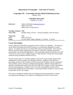
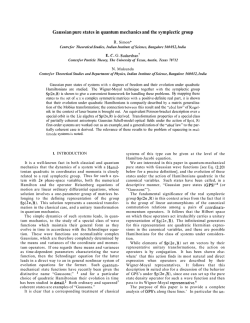
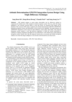
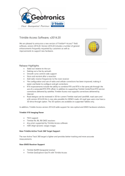
SFSU Guide to Trimble GPS with Terrasync This Guide provides the essentials for using the Trimble GPS units (Juno for 3-5 m accuracy, ProXH and GeoXH for submeter) to collect data points and other features using Terrasync. Data can be post-processed, and the setup can be configured to accept a Laser Rangefinder with Compass for offset shots. This guide documents its use with TerraSync software to collect points, lines and polygons. For more information, see the Terrasync Software Getting Started Guide (224 pp) which you can download from: http://www.trimble.com/terrasync_ts.asp and the manufacturer’s Juno, GeoXH or ProXH manual. Contents Physical Setups ............................................................................................................................... 2 Juno ............................................................................................................................................. 2 GeoXH 2008 ............................................................................................................................... 3 GeoXH & Zephyr Box Organization .......................................................................................... 4 GeoXH & Zephyr Rangepole Setup ........................................................................................... 6 ProXH + Recon ........................................................................................................................... 8 Trimble ProXH & Recon Parts List & Box Organization .......................................................... 9 MDL LaserAce Rangefinder..................................................................................................... 10 Backpack Setup for GeoXH or ProXH with Rangefinder ........................................................ 11 Basic Process of Using a Trimble ................................................................................................. 12 Terrasync Screen Layout .............................................................................................................. 13 Status Bar .................................................................................................................................. 14 Terrasync Sections ........................................................................................................................ 15 Terrasync sections: Status ........................................................................................................ 15 Terrasync sections: Setup ........................................................................................................ 16 Terrasync sections: Data .......................................................................................................... 18 Terrasync sections: Map .......................................................................................................... 19 Field Methods ............................................................................................................................... 20 Capturing a Feature with GPS Positions................................................................................... 20 Create a data dictionary in the field .......................................................................................... 22 Offsets ....................................................................................................................................... 23 Complex Offsets ....................................................................................................................... 25 Downloading & Post-processing with Pathfinder......................................................................... 29 Differential Correction .............................................................................................................. 30 Exporting to GIS ....................................................................................................................... 31 1 PHYSICAL SETUPS Physical Setups Juno (Figure from Trimble Juno manual). Note that the unit is inside an Otter Box, so it looks a bit different, and the buttons are inside black rubber covers. The Power button can be pressed by pushing on the black rubber cover at the right place. 2 PHYSICAL SETUPS GeoXH 2008 (Figure from Trimble GeoXH manual). 3 PHYSICAL SETUPS GeoXH 6000 (Figures from the Trimble GeoXH Quick Start Guide) 4 PHYSICAL SETUPS GeoXH & Zephyr Box Organization In Yellow Box partitions In left back partition: ☐ Range pole mount, 2 parts: o Pole connector, with or without integrated bubble level & compass. (The rangepole has a bubble level attached) o GeoXH holder ☐ AC adapter ☐ USB cable In center back partition: ☐ Zephyr Antenna ☐ Antenna cable (fits underneath) In right partition: ☐ GeoXH support module for charging and interfacing (gray) (not used in GeoXH 6000 – USB and charger plug in directly) In front partition ☐ GeoXH in yellow pouch Other parts not shown: ☐ Range pole in nylon bag ☐ Range pole bipod Pole connector with level GeoXH holder 5 PHYSICAL SETUPS GeoXH & Zephyr Rangepole Setup For benchmarking purposes, you need to collect positions with the antenna mounted a known distance directly above the benchmark, so we use a 2-m range pole. Zephyr Antenna connected by antenna cable In Terrasync, go to Setup/Logging Settings/Antenna Height to: 1. Enter the 2.0 m antenna height. 2. Identify the Zephyr as the antenna type. See the easier but less accurate backpack method later in this document. Look carefully: antenna cable must be inserted into the GeoXH up to the line on the cable plug. GeoXH mounted on pole with two-piece assembly, can be positioned for best visibility. Pull the elastic strap behind the mount for security. Either hold pole in place manually, or use bipod, shown here, for longer data collections, especially useful for benchmarking. Zephyr mounted on 2-part range pole, which is 2.0 m from the base of the antenna to the point at the bottom. Circle level for maintaining vertical position. 6 Bipod legs have push-button quick releases for adjusting the length. Once the feet are firmly in the ground, use the releases to level the pole. PHYSICAL SETUPS Longer Extension using Prism Pole In riparian areas and other points where getting a GNSS signal is difficult, a longer range pole may be employed by using one of our prism poles that extends to 4.51 m. With the graphite GPS range pole extenders (shown on the previous page), you can get this to 6.426 m, which can really help in these situations. However, you need to be careful, and use the following guidelines: You will need the 5m antenna cable. If you are extending the antenna through branches, you need to be careful to (a) extend exactly vertically (not easy to do), (b) not damage the antenna cable. Using Velcro straps to wrap the cable around the extension pole can help. Set the antenna height correctly in Terrasync. Note that the prism pole has markings on it that indicate the height of the prism above the base of the pole, however the prism when mounted is 0.14 m above where your antenna mount is, so the antenna height setting must take that into consideration. With the two extenders, the antenna height = prism pole marking + 1.776. To avoid potentially making a mistake in the field, the simplest approach is to use a table of antenna heights at the maximum reach of each prism pole section. The following table assumes that two graphite extensions are mounted between the top of the prism pole and the antenna: Prism pole height reading (max reading for each section) Antenna height to enter in Terrasync 1.65 3.426 2.65 4.426 3.65 5.426 4.65 6.426 7 PHYSICAL SETUPS ProXH + Recon The ProXH provides submeter accuracy after postprocessing, and can be configured to accept a Laser Rangefinder with Compass for offset shots. This guide documents its use with TerraSync software to collect points, lines and polygons. The basic process of using the instrument with TerraSync is as follows. See the subsequent sections describing the different section menus of TerraSync. 1. Make sure you have all of the equipment, taking care to maintain all equipment carefully. Note the organization of the black box (next page). 2. The night before you plan to use it, charge all of the instruments, and secure extra batteries for the rangefinder (2 AAs). 3. Hook up everything, and turn on Recon and ProXH GPS receiver. Measure the height of the receiver above the ground. 4. Start TerraSync from the Start menu. Tap the window icon, then select Programs/TerraSync. 5. Move to where the receiver has a good sky view. 6. Check the Status (p. 3) to make sure everything's working, and to see what satellites are available. If GPS is disconnected, go to setup. 7. Change the Setup as needed to get the GPS connection working, set up real-time differential correction, and configure a laser rangefinder for offsets. 8. Configure the Map view so we can see where we are, in reference to previously created points, or other map layers. 9. Use the Data area to create files and and capture GPS data points. 10. Download the data to your computer, and remove it from the Recon. 11. Return all parts in good condition, and organized in the box as illustrated. 8 Range pole setup, including: ProXH GPS receiver, mounted on quick-release bracket (GPS-BR) at top of range pole. If you need offsets, one option (shown here) is using a rangefinder such as the MDH LaserAce shown here. Can also be handheld. Uses Bluetooth interface. Recon PDA running Windows CE, attached to range pole with quickrelease mount on side of LEVEL attachment. Connected to GPS with serial cable, and to LaserAce and GeoBeacon (not shown) via Bluetooth. PHYSICAL SETUPS Trimble ProXH & Recon Parts List & Box Organization In Black Box partitions In back partition: ☐ GPS1 or 2: Trimble ProXH receiver ☐ GPS Charger 1 or 2: Power Supply for wall charging serial cable USB cable GPS brackets In center partition: ☐ Recon1 or 2: Trimble Recon in nylon case ☐ Recon Charger 1 or 2: Power Supply for wall charging Recon In right partition, if using: ☐ GB1 or 2: Geobeacon ☐ Geobeacon charger 1 or 2: Power Supply for wall charging In large left: ☐ GPS-BR1 or 2: bracket for connecting GPS to top of GPS range pole (red Laser Technology). Bracket top has screw mount to lower push-button part. GeoBeacon GPS-BR ☐ RC-BR1a & RC-BR1b or 2: two-part bracket for holding Recon on range pole. ☐ Belt with pouch for GeoBeacon, if using. ☐ LEVEL1 or 2: for leveling the range pole; includes a compass and bubble level. Will attach to RC-BR1a, so can be used instead of RC-BR1b. In pockets: ☐ Serial cable ☐ USB cable Other parts not shown: ☐ Range pole in nylon bag ☐ Range pole bipod ☐ Rangefinder with all necessary parts and manuals. 9 LEVEL RC-BR1a PHYSICAL SETUPS MDL LaserAce Rangefinder Needs 2 AA batteries Bluetooth connection with GeoXH If using with range pole, you need the bracket. Turn on by pressing the Fire Button. It will display a couple of numbers, then display MODE 1, the normal mode to use it. Before measuring points, go to setup to do the tilt calibration, and maybe check the settings. Setup. Press from MODE 1. After changing a setting, you must press the Fire button again to save it. To exit, press & simultaneously. Essential setups: 1. Tilt calibration, should be done every time the unit is turned on. Must be stable, and approximately level: nestled on a jacket on a stable surface or mounted on a tripod. Do not handhold. Press to toggle to 'Yes', and press FIRE. Do not disturb the instrument while it calibrates. After a short period (4 or 5 seconds typically) the unit should go to the next setup (2 CAL: compass calibration). 2. CAL. Compass calibration. Needed if you are in an area with a different magnetic interference situation. See the longer guide to do this. It takes a few minutes. 3. Unit. Meters 4. Angle. Deg 5. Auto power on/off. If not already, press to toggle to No. Otherwise it’s a pain to have to do the tilt calibration over each time you turn it on. Just remember to turn it off when you’re done, to save batteries. 6. IF 1 (doesn’t seem to matter) 7. Baud 9600 8. dEV 14.2 or whatever the magnetic deviation is for your area. Note: this may also be set in Terrasync. Only set it in one place, not both. 9. ACAL no To take a reading, from MODE 1, point it by sighting through the eyepiece and putting the red dot on the object, then press Fire for about a second so you hear a two beeps. If the second beep is much shorter, it worked and you’ll see the readings displayed. If using with the GPS, and a point is open, you’ll hear a signal from the GPS and the message ‘Offset Received’ will be displayed. Turn off by holding down press & simultaneously for several seconds while it counts down. 10 PHYSICAL SETUPS Backpack Setup for GPS with Rangefinder For 1-2 meter accuracy applications Don’t need range pole, backpack sufficient Offsets for trees or other features, up to 300m distant, using handheld rangefinder Parts needed Backpack with 5/8” mount for antenna Rangefinder in upper pocket GeoXH and Zephyr antenna or ProXH & Recon Antenna cable (or Recon to ProXH cable) Spare AA batteries in outside pocket Things to remember: Rangefinder must be on while using Terrasync Setup/External Sensors to detect it through the Bluetooth connection. It loses this connection every time the rangefinder turns off, so you must re-establish it. Magnetic declination: Both rangefinder and Terrasync can set this. Make sure to have only one do so. If it’s set in the rangefinder, use Terrasync: Setup/Units to set magnetic declination to 0.0 Offsets can be sent (by firing on a point) at any time while point is open. If received, “Offset Received” will be displayed in Terrasync. For best accuracy, pause logging of the GPS while positioning the rangefinder where the antenna has collected data. LaserTech Rangefinder: This is also a good choice for distance and vertical angles, but it does not have Bluetooth, so the GPS cannot interface with it, so you need to record data manually by entering offset values. Use a handheld compass or the Mapstar compass module (you may want to let Terrasync do the magnetic declination correction). To turn on, press either left or right rear button. To turn off, press two forward buttons on the left. To take a reading, make sure you’re in HD mode (cycle through modes with the middle right button), then press right rear button to get HD (horizontal distance), then cycle through the various displays to see VD (vertical distance), SD (slope distance), INC (inclination in degrees). Depending on your Terrasync Setup/Units settings, enter either SD & INC or HD & VD, along with azimuth from the compass. 11 THE BASIC PROCESS Preparation & Process of Using a Trimble The basic process of using the instrument, with TerraSync, is as follows: 1. Charge it the night before you plan to use it. Juno: when fully charged a light on the side (a bit hard to see) goes to solid green. 2. Make sure you have all of the equipment, taking care to maintain all equipment carefully. See the box organization figures above for the GeoXH and ProXH. For the Juno, this means: The unit, in its Otter Box. Note: this unit is not waterproof. A wall charger. USB cable for downloading data to a PC. 3. Start TerraSync from the Start menu. Tap the window icon, then select Programs/TerraSync. 4. Move to where the receiver has a good sky view. 5. Check the Status (p. 3) to make sure everything's working, and to see what satellites are available. If GPS is disconnected, go to setup. 6. Change the Setup as needed to get the GPS connection and differential correction working. 7. Configure the Map view to display map and background layers. 8. Use the Data area to create files and and capture features with the GPS. Ideally, prepare a data dictionary in advance to facilitate efficient and accurate feature collection. You can also create a data dictionary in the field. 9. Download the data to your computer, and remove it from the GPS or data collector. 10. Return all parts in good condition, and organized in the box as you received it. Antenna Settings: 1. If you’re using an external antenna, like the zephyr, make sure it’s plugged in well. There is a square edge that should be lined up with the square side of the hole. When you start Terrasync and turn on the GPS, you should see a brief message saying ‘External antenna connected.’ – that’s your only indication that it’s hooked up right. Go to Setup/Logging Settings/Antenna Height to get to Antenna Settings. Then select the right type of antenna, and where to measure height to. For the Trimble 2part graphite range pole, set this to 2.0 m. For the backpack setup, you should measure the height in m of the antenna base above the ground while standing. 2. If you are using the receiver without the external antenna, you may need to make sure that you’ve set it to use the receiver, by going to the Antenna Settings. 12 SCREEN LAYOUT Terrasync Screen Layout The user interface in Terrasync is reasonably clear, consisting of a couple of menus, a status bar, various buttons, and a display area that varies with the choice. The Section button is a menu pull-down giving access to the primary subsystems of the software: Map: Displays a map with any background layers and captured GPS points. Data: For opening or creating new data files. Use this to start collecting points. Once initiated, you can go to the map view to collect features into an open file. Navigation: We won't be using this, but allows you to navigate to saved points. Status: For determing the satellite configuration, planning time to collect, and checking the status of satellites, external sensors, etc. Setup: For reconnecting the GPS or differential correction inputs, setting coordinate systems, etc. 13 SCREEN LAYOUT Status Bar The status bar remains visible in all screens, and provides you with constant information on the status of satellite reception, accuracy, etc. It includes many icons, including: Satellite icon: shows the number of satellites being tracked, and flashes when the PDOP is poor. The number flashes when not enough satellites are available. If the GPS will animate. is not connected, the connection icon Real-time correction source icon: The SBAS icon shows that it is receiving realtime corrections from the SBAS satellite. You can also see an icon for this satellite on the sky chart. Battery status: Left half shows the charge level of the GPS receiver battery; right side shows the status of the field computer's battery. For the Juno, these are both in one unit. Yellow means the power level is low, red means it's critical. Estimated Accuracy icon: The type of accuracy depends on the settings in the Accuracy Settings form (in Setup/Logging Settings/Accuracy Settings button). By default, the accuracy is the field accuracy. Tap the number to temporarily display a postprocessing accuracy estimate. Logging icon: Shows that you're logging a feature with code accuracy (Carrier accuracy would also display the carrier time.) The number displayed is the number of positions logged so far. A red bullseye symbol is shown for when logging multiple vertices for a line or a point feature . Other icons are documented in the Getting Started guide. 14 TERRASYNC SECTIONS Terrasync Sections Terrasync sections: Status Skyplot: Select Status in the Section (upper) menu. Select Skyplot in the subsection (lower) menu. At the top is the status bar, described above. The satellites in white boxes (e.g. 27, 20, and 03 in the figure) are being tracked but not being used to compute positions. The satellites in filled (black) boxes are being used to compute positions. The width of the bars represents the signal strength of that satellite The red circle shows the minumum elevation angle required to use a satellite. The overall satellite geometry (PDOP) is shown on the right as a vertical bar, with the configured minimum quality as a horizontal mark. The bar will be black if above this mark. The current positions, datum, and PDOP values are displayed. For the Juno, the GPS settings are displayed at the bottom, with MaxPDOP, Min Elevation, etc. These cannot be changed in the Juno, but you have other means of limiting collection based on Accuracy-based logging. For the higher-end Trimble units, like the GeoXH, a slider bar allows you to favor productivity vs precision. Finer precision requires a lower PDOP. If you need to work in areas with interference, you may need to boost the productivity, degrading the precision. You can see the effect of this setting on the overall satellite geometry setting. Other Status Sections: Satellite info: more info on each satellite Receiver Real-time Plan: for mission planning. Shows more info about satellite availability. Sensor Comms: shows com port use. 15 TERRASYNC SECTIONS Terrasync sections: Setup One common use of Setup is to connect the GPS, needed if the map or data display shows 'GPS is disconnected.' Assuming GPS settings are correct, this simply means to click the GPS button. But there are many more settings: Get to Setup from the Section menu. Some common settings: Logging Settings, for antenna height, accuracy settings, what to record, etc. See next page. GPS Settings, if necessary, to change which GPS you're talking to, and maybe to change settings like maximum PDOP, minimum 'elevation' (angle above the horizon to require satellites to be), RTK. Real-time settings, to select a GeoBeacon or choose other real-time correction signals like WAAS. Using real-time correction however makes it more accurate for navigation to stored locations, like previously sampled sites. The real-time settings allow you to choose a real-time differential correction source and organize them hierarchically. Recommendation: Choice 1 "Integrated SBAS" (WAAS in the US); Choice 2 "Use Uncorrected GPS". SBAS will get you to submeter accuracy with the XH, but not with the Juno. Note that (with the XH) you can also post-process the data to get to better accuracy ~ 10-50 cm. Coordinate system, if you want to use something other than lat-long WGS84, HAE, for display. May want to set to UTM perhaps. I usually prefer UTM WGS 84 with elevation set to MSL (mean sea level) or UTM NAD83 if using a background image in this datum. Units, to change distance, velocity, type of lat/long etc. External Sensors, for selecting the Laser Rangefinder. You may be prompted to select the GPS device. If you want to use a laser rangefinder, this should be attached, with either the serial cable or bluetooth. 16 TERRASYNC SECTIONS Logging Settings You would use these to set: accuracy settings (see below) antenna height (see below) choice of logging carrier data (for XH – Juno only logs code data) choice of logging velocity data – useful if you are recording points while moving setting up creating new features by time or distance. filename prefixes. … and a few other things… Accuracy Settings Sometimes you may want to limit your collected positions to a maximum accuracy estimate. Go to Setup/Logging Settings/Accuracy Settings and set Use Accuracy-based Logging to Yes, change the Required Accuracy. Then capture some more features to see the effect. Antenna Settings You can use this to set the antenna or receiver height above the point of interest. If you have an external antenna hooked up, you will need to make the correct settings. Go to Setup/Logging Settings/Antenna Height to get to Antenna Settings. Then select the right type of antenna, where to measure height to. For the Trimble 2-part graphite range pole, set this to 2.0 m, which is the height from the tip of the pole to the bottom of the antenna mount. 17 TERRASYNC SECTIONS Terrasync sections: Data To collect a series of GPS points as a new file: 1. Go to Data view. 2. On lower pull down, select New. 3. Set the location folder, provide a file name, select a dictionary if you have one created, and make any other selections on that screen. (The default data dictionary is ok for generic points, lines and polygons.) 4. Click Create. 5. Specify the antenna height. For a handheld unit, you may want to estimate how high you will hold it above the ground, but the vertical accuracy is probably at least 5 m, so this isn't so critical. 6. You should see a Create button with a round blue symbol, and also a selection of feature types: point, line or area. Once your GPS is positioned and steady (use the bubble level) at a point you want to collect, you can either click the the feature type to create a new point. button or double-click 7. At this point data will start to collect (unless you have Log Later set) – you'll see positions accumulating in the top bar with a pencil drawing thing and a count of positions – also displaying the post-processing accuracy to expect. While you are collecting data, shown as numbers incrementing to the left of the window close X button, you can enter in a Comment, or any other attributes, in the fields shown. You probably want to collect a lot of positions to average for accuracy, so you probably have plenty of time to enter useful attributes. If you're not at the point, unless you are using log later you may want to pause right away if you're not ready to collect positions. You can then press the same button to start or resume logging when you're ready for the positions. You can collect data in the Map View as well as the Data View. In the map view, the create feature button will just be a small blue solid circle. Note that the unit will continue to log between features collected. You can pause and restart this as you go. 8. Use the map view to see what you're collecting, while you're collecting it. You can create new feature objects while in the Map View, though the data interface is less complete than the Data interface. See the map section below... Create : New feature Log : "Go" Pause : "Stop" temporarily Ok : "All done" 9. Close the file. There's a close button. Pretty obvious. There's also a window closing X that exits the whole program. 18 TERRASYNC SECTIONS Terrasync sections: Map While we could use the GPS without a map display, it's nice to be able to see where we are in relation to existing map or image layers. Tools: The map display includes options and display tools. You can pan and zoom, and get information about features. Typically panning to include the GPS points is automated. You can also digitize features on the map display. These use the same data files you create for GPS points. If no Create Feature icon, feature is open, you can tap the blue but make sure that GPS data collection is paused. Use the digitize tool . Creating manual positions: you can enter coordinates directly. A file must be open (see Data section), with GPS paused, and the digitize tool selected; then go to Options and select Enter coordinates. If you have a file open and your GPS is hooked up and Create Feature to receiving positions, you can also use the capture points in this view. This is a little nicer than in the Data view since you will see a map. Background Layers: It's very useful to include a background map or orthoimage. Use the Layers button to access this. To add one previously loaded onto the unit, identify the Location, File Type, and File. To load a file, first get it into JPEG format and in UTM coordinates. Then connect the unit to a PC with the USB cable, and let Microsoft ActiveSync start up. (If this doesn't happen, you may need to download ActiveSync first.) Then use its explore button to access folders on the unit. Then copy the files you want (e.g. campus image files in P:\Courses\Exted\G9010\data) into the TerraSync folder on the unit. Supported Orthoimages At this version of TerraSync, only BMP or JPEG files seem to be supported. You should save both the jpg (in UTM) and the jgw (world file) in the TerraSync folder, then it will appear as available as a background file. Note: be careful to set the coordinate system to that of the orthoimage. 19 FIELD METHODS Field Methods Capturing a Feature with GPS Positions Capturing points are simple, lines and polygons simply add multiple vertices. First, understand that any time you collect a GPS point feature with Terrasync, you will be using a data dictionary. You can either use one you've created or use the generic data dictionary which will provide a generic point, line and area feature type. This page describes capturing generic points, lines and polygons, with one 'comment' attribute, but the same process applies to capture features with more elaborate data dictionaries. To capture a point: In the Data area, create a new data file, naming it what you want and pressing the Create button. In the Confirm Antenna Height screen, set the antenna height above the feature you want to record (perhaps the ground). Make sure the subsection menu is set to Collect Features, then choose the Point_Generic feature type and push the button to start collecting positions for the feature. Note that the blue circle symbol will also be used when in a map view, and means 'create new feature'. Note that positions will start to collect, and you'll see a red target symbol with the number of positions collected displayed in the upper right. For the generic data dictionary, a comment field will appear that you can fill in with data; your custom data dictionaries will probably have more fields (see the Data Dictionary section below). Enter the values that you want to associate with the point, and wait until you have 10 or 20 positions collected before you press OK. For benchmarking (with the submeter units), you will probably want hundreds of points, with the GPS antenna mounted on a rangepole with bipod stabilizers. Make sure to set the appropriate Antenna settings for your configuration, or you may not be reading the antenna. See the Terrasync Setup section above. 20 FIELD METHODS To capture a line (or polygon), some options should be considered: Log Later. A recommended method is to use this option, so you can add parameters before starting to collect positions. Enter the parameters, but don't press Ok – the same as with Log Now, this would close the features. There's a green Log button for when you are ready to start. Press the red square stop button when you're finished with the feature. Positions as vertices: Normally when you log a line or area feature, every position can potentially become part of the feature as a vertex. Start by selecting a new feature of line_generic or other line type. You can log a series of positions while walking. You can control which positions to use by pausing the position logging, then restarting. Points as vertices: Capture the path as a series of vertices, waiting at each one. For each vertex, stand at a location and use Options/New Vertex method to initiate the vertex, and capture it like you captured a point, with averaging. A message will be displayed: "Vertex 1 open Remain stationary". The red stop square button refers to the vertex. Wait at each vertex until you have at least 20 points averaged, then press the red stop button to close the vertex. Note that when you stop it, another red stop button appears – this refers to the feature. Since it's not logging features unless you tell it to, you can move to the next vertex and repeat the process. After you've Ok'd the last vertex, Ok again to close the feature. Positions, Features and Vertices: know the difference. Positions are the individual GPS locations the unit captures by trilaterating from the satellites. Each position will be differentially corrected in real-time or in post processing. Features are the points, polylines and areas you can create from positions. For a point feature, you can either create it from a single position, or by averaging a number of positions, for improving accuracy. Vertices are the points along a polyline or polygon boundary where the line changes direction. Vertices may be single positions, say if you want to collect the path of the line while moving, or may be points created by averaging multiple positions, using the same method used to create the point features. Interrupting a line or polygon: If you are recording a long line or polygon boundary and you want to stop to capture an individual point along the way, you can do so by: 1. Close the line by pressing Ok. 2. Capture the point as a new feature. 3. Change the submenu from Collect Features to Update Features, select the line feature you just closed, and when prompted specify that you want to continue, not replace the feature. 21 FIELD METHODS Create a data dictionary in the field Purpose of a Data Dictionary A dictionary is handy when collecting feature data that may have attributes. We could use a field notebook for this, but you can avoid errors and speed data collection by creating an efficient dictionary. Data dictionaries allow us to create a variety of different attribute types, including the ability to select from lists of possibilities. We might, for example want to record tree types selected from a list of "pine", "oak", "elm", etc., or maybe we know how to identify them to species and want to select from "Pinus ponderosa", "Quercus agrifolia", "Abies concolor", etc. Data dictionaries support quite a few data types, including images such as photographs you take with the Juno of features you want to georeference with the GPS. You need to first create this dictionary, which you can use Pathfinder for, but you can also create in the field with TerraSync, which we'll do here. The basic process is: 1. Go to the file manager, then Options to specify a New Dictionary. 2. Create "features" (really feature classes, since you'll be saving multiple feature records in the file) of points, lines or areas. Each feature will eventually saved as separate GIS files. For example, in the Edit Dictionary window, use Edit to create a New Feature called stream crossing (point or line) or tree (point) or gully head (point) or vegetation patch (polygon) or trail (line). 3. For each feature, create its attributes (numeric, text, date, time, menu). In the case of menu attributes, enter the possible values to select. For example, for trails, you might have a surface menu attribute, with values "paved", "dirt", and "gravel". For tree, you might have tree type with choices "White Fir", "Ponderosa Pine", etc. One interesting attribute is a picture, selected as a file. 4. Save the dictionary. 5. To use the dictionary, when you are creating a new data file, you choose the dictionary. Note that if you want to change the data dictionary, you can do so, but you would need to create a new data file to capture additional features. 22 FIELD METHODS Offsets If you cannot occupy a desired feature with the GPS, but can see it from a location where you can get GPS, you can use various offset methods: Simple Slope/Inclination offsets with distance, compass direction, and vertical angle. Complex offsets with more than one GPS point and some combination of distances or compass directions. An offset can be recorded with a collected point or vertex, and this is retained with the data. The actual GPS point might get real-time differentially processed or post-processed, and then the saved offset is applied to the feature you are after. The offset is always from the GPS toward the feature. This convention makes it easy to use solo methods where the user is holding the GPS and might be using a laser rangefinder to shoot distances to a desired feature. Simple Offset Azimuth 78° Vertical +25 Complex Offset: 2 azimuth type 23 FIELD METHODS Simple Offset – with Distance, Compass Direction and Vertical Angle First we need to set up the GPS to use the offset format we are going to provide. In Setup ... Simple Offset Azimuth 78° Vertical +25 Units set the Offset Format to Slope/Inclination (instead of Horizontal/Vertical where we would need both of those distances); and set the North Reference to Magnetic (since our compasses read magnetic directions.) Also make sure the Distance Units are set to Meters. Open your data file, and go to Collect Features mode, and survey a feature that you can't stand next to and get a decent point. Measure the slope distance, vertical angle and compass direction (for best accuracy with a handheld compass, do a backsight of the compass direction), and while collecting your GPS point, use the Options button to go to Offset, and enter the compass bearing in degrees, the slope distance and the inclination (make sure to enter negative or positive as appropriate). Collect some more. Try staying at one GPS point, and "spraying out" to multiple tree features. Each point needs to be collected as a GPS point, since only one offset is saved with each point, but this will illustrate a process we will use with submeter GPS. If you are using a connected rangefinder, you can fire it any time to bring in an offset. If it gets a valid offset, a special offset display will appear, asking if you want to use it. Notes: You can also enter in an offset by using Options/Offset and entering the azimuth, horizontal distance and vertical distance, or slope distance and vertical angle, depending on the Offset Format settings in the Units area of Setup. The Laser Rangefinder may be set to provide true azimuths. You don't want to convert these twice, so make sure the settings are correct. This is a common blunder! Your GPS point being collected is probably set to the base of the rod, your GPS, assuming you've entered a rod height. So your vertical angle is from the base of the rod to the feature. But your rangefinder probably isn't positioned there, so you need to shoot to a height above your target Magnetic Declination Setup/Units Settings equivalent to the height of Using a compass that does not correct for declination (Suunto): your rangefinder above the North Reference: Magnetic base of the rod you're Magnetic Declination: Auto or a known declination holding. Using the rangefinder or a compass that is correcting already: North Reference: True Magnetic Declination: 0.0 24 FIELD METHODS Complex Offsets TerraSync also has the capability of doing "complex offsets" where you use two or three GPS positions together with either distances or compass bearings. These are handy in two situations: You don't have a compass or clinometer with you, but you either (a) have a distance device like a tape or a rangefinder; or (b) you know how to pace your distance. You can use trilateration. You can't physically get to the point you need to locate, but you have a compass and can see the point from three surrounding GPS points, using triangulation. Offset Options Distance - Bearing Distance - Distance Triple Distance Bearing – Bearing Triple Bearing GPS pts 1 2 3 2 3 Requires 1 Slope distance and 1 compass bearing 2 Distances and left vs. right setting 3 Distances 2 Compass bearings 3 Compass bearings – must have an error check Pacing Distances For the 3-5 m accuracy of the handheld GPS, pacing accuracy is sufficiently accurate. First, we need our pace distance. Count your extended paces over the 100-m course that the instructor specifies. Note that a pace is two steps, so starting with your left foot it's each time you put your right foot down. Extended paces are stretched out, more consistent than normal walking. Do this four times, back and forth twice, and record the number of paces here: ____________ ____________ ____________ ____________ sum = __________ Add them up and divide 400 by this number to get the length of your pace in meters, and write this down, to two decimal places: 400/sum = __________ [There is a calculator program on the GPS data logger] Considerations for complex offsets Using more than one GPS points to find a desired feature point employs triangles, either using triangulation or trilateration methods. Triangles work best when they are not too skinny, with the ideal shape being equilateral with each corner at 60°. So, in creating either a single triangle with two GPS points or a feature, or creating multiple triangles, you should try to spread your points out. With three points, you should try to surround your feature on all sides. This is the same issue as with GPS where we minimize the PDOP by collecting when satellites are spread apart. 25 FIELD METHODS Distance - Distance 2 1 To capture features using the Distance-Distance method: 1. Setup/Units: Offset format: Slope distance/Inclination. 2. Before creating a point, when in collection mode, select the Log Later option (Options). 3. Create a point feature, but before starting logging, use the Options button to change the Offset method to Distance - Distance. 4. This will start up a process which is somewhat self-explanatory on the screen: a. Move to a suitable GPS point (1) and press Log to start logging the reference position. b. Press Next (and the position collection) and you will be prompted to enter the first distance (A): you'll pace the distance, then enter the result in the slope distance field. Leave the Inclination at zero for reasonably flat areas, or measure it. c. Press Next and follow instructions to move to the next GPS point (2) you'll probably be pacing from the feature, so go ahead and figure out the distance.) d. Resume to collect that second GPS point, then Next to enter the distance. e. After the last point, you will also need to enter the direction of the feature from the line you travelled between 1 and 2. (In the above figure, it would be Left.) f. Ok the result and close the feature the normal way, once you’ve entered any necessary attributes. 26 FIELD METHODS Triple Distance 3 2 1 To capture features using the triple distance method: 1. Setup/Units: Offset format: Slope distance/Inclination. 2. Before creating a point, when in collection mode, select the Log Later option (Options). 3. Create a point feature, but before starting logging, use the Options button to change the Offset method to Triple Distance. 4. This will start up a process which is somewhat selfexplanatory on the screen: a. Move to a suitable GPS point and press Log to start logging the reference position. b. Press Next (and the position collection) and you will be prompted to enter the distance: you'll pace the distance, and use the calculator to multiply your paces by your pace distance, then enter the result in the slope distance field. Leave the Inclination at zero unless you’ve measured it. c. Press Next and follow instructions to move to the next GPS point (you'll probably be pacing from the feature, so go ahead and figure out the distance.) d. Resume to collect that second GPS point, then Next to enter the distance. e. Repeat for the third point. You'll want to pace from the feature to that point: all three distances are from the feature to the GPS point in question, or vice-versa. f. Ok the message saying the position has been calculated. g. You should be back at the feature creation point, where you can close it once you’ve entered your attributes. 27 FIELD METHODS Bearing – Bearing & Triple Bearing Bearing-Bearing and Triple Bearing Offsets are handy when you can’t actually get to the point in question. Maybe there’s too much poison oak, or there are monsters or steep cliffs between you and the feature. The only limitation is that compass measurements are not very accurate, though they are probably as accurate as pacing. To capture other features using either the Bearing-Bearing or the Triple Bearing method, you use the compass to shoot from the GPS points to the feature. Note that with three points it is able to detect errors, and it may not like the accuracy of the bearings you read if they don't intersect well. 1. Setup/Units: Set the North Reference to Magnetic unless you are working with a compass that provides true azimuth. 2. Before creating a point, when in collection mode, select the Log Later option (Options). 3. Create a point feature, but before starting logging, use the Options button to change the Offset method to Bearing – Bearing or Triple Bearing, depending on how many points you’ll be using. 4. This will start up a process which provides pretty clear steps on-screen. a. Move to a suitable GPS point and press Log to start logging the reference position. b. Press Next (and the position collection) and you will be prompted to enter the azimuth, so measure this and enter it. c. Press Next and follow instructions to move to the next GPS point. d. Resume to collect that second GPS point, then Next to enter the azimuth from this point. e. If doing Triple Bearing, repeat for the third point. After the last point, you will see a message that the position has been calculated, and you can Ok it. f. Close the feature after entering attributes. 28 PATHFINDER Downloading & Post-processing with Pathfinder Whether or not you post-process, you will need to download your data to bring it into a GIS. We'll use Pathfinder to do this. 1. The computer needs Microsoft ActiveSync working and current. 2. Attach the unit with the USB cable. You should hear a happy sound when ActiveSync starts up and detects the unit. 3. Start GPS Pathfinder Office, and either open an existing project you created earlier, or create a New... project – specify a 'workspace' folder (it will create a new one if you provide a path that works. Note that it will create the folder you name, and within that folder will create a Backup, Export and Base folder. 4. Utilities/Data Transfer. Check the connection in the devices area, then with the Receive tab, click Add ... Data File then specify the file(s) to Open from the field computer/GPS, then Transfer All to get all of the data from this file. Close your way back to the main GPS Pathfinder window. 5. Open the file you transferred and you should see it displayed in the map. Note that some 'features' may be messages that you lost the carrier signal, etc., but the ones you've captured as features should have the attributes you've assigned. To scroll through them, use Data/Feature Properties or Position Properties to display a list you can scroll through. You can also select features with the mouse. Offsets: Note that features with offsets retain their GPS coordinates – this must be the case since they must be post-processed as GPS data. The offset information is thus stored with the feature, and can be seen by clicking the Offset... button. 29 PATHFINDER Differential Correction Start the Differential Correction wizard, to correct files with nearby public base stations. You may need to wait a day or so before the files are available. You can probably use the default settings. The Junos use code, not carrier phase, so you could specify to do Code Processing Only, but the Automatic Carrier and Code Processing seems to work. You can create a Base Provider Group, or select an existing one you created earlier, that is composed of nearby stations. Each station has a distance attribute set from the positions you're trying to collect. The Integrity Index is a quality indicator ranging from 0 to 100, with 100 being the highest, and is based on bias, precision and reliability, resulting from a variety of factors, combined with the baseline distance from the rover to the base station. I'm not completely sure why there are so many '?'s or what to do with them. Select base stations as close as you can find to your field area. The Junos use code, not carrier phase. If you were using real-time SBAS differential, you probably can't improve on this by post-processing. It sometimes helps to delete a previous base station folder if the first try at differential correction doesn’t work. 30 PATHFINDER Exporting to GIS GPS data files used by Terrasync and Pathfinder are not readable in ArcGIS, so we’ll export to shapefile format. We must do this correctly to ensure the data have the attributes we want and are in the correct projection. To export, go to Utilities/Export… to bring up the Export window. Properties You will need to go to the Export Setup Properties to control the export projection, attributes and other properties. Access the various properties through the tabs: Projection: Pathfinder can export the native GCS WGS84 coordinates into whatever coordinate system we want to use, but we need to not only specify it, but also select a projection file to go along with it: Export Coordinate System: You can select any projected coordinate system, or datum, GCS, that the program knows about, which is many. You can either specify an “Export Coordinate System”, or reference the “Current Coordinate System”. Projection File: You need to also specify a projection file corresponding to your export coordinate system. [Why the program doesn’t do this for you automatically I don’t know. The way this works, it would be possible to select the wrong one.] 31 PATHFINDER Attributes (and other settings): By default, Pathfinder exports the minimum attributes set by your data dictionary. For normal GIS use, this is all you need. However, GPS features are recorded with many GPS-related attributes that you may find useful: Date and Time Recorded: Very handy for recording exactly when a point was recorded, especially when collecting samples or measurements when this information is critical. Accuracy data: PDOP, HDOP, Vertical and Horizontal Precision. Elevation: Height above the ellipsoid or above mean sea level. Line and Area feature measurements: lengths, area, perimeter, average and worst precision. Position Filter: You can choose to only export features of a specific accuracy grade, based on the technology used in collecting them. By default, it only exports features based on differentially corrected positions. Sometimes you will want to also get uncorrected positions. Exported Shapefile Names and Locations By default, exported shapefiles will be stored in the Export folder of the project. You can Browse to change the folder. A good idea might be to specify a new folder within the Export folder by adding it to the path and allowing the system to create the new folder. The shapefiles will be named according to the feature types in the data dictionary, with names up to 8 characters. For example, the default points will be stored as Point_ge.shp. If you have created a tree feature, they’ll be exported as tree.shp, etc. If you use the same project to export new data, these will write over old export files, so you may want to rename old ones first. 32


© Copyright 2026