
A miniature robot that autonomously optimizes and
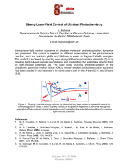
A miniature robot that autonomously optimizes and
maintains extracellular neural action potential recordings
Edward A. Branchaud, Jorge G. Cham, Zoran Nenadic,
and Joel W. Burdick
Richard A. Andersen
Division of Engineering and Applied Science
California Institute of Technology
Pasadena, CA 91125
[email protected]
Abstract – This paper describes a novel miniature robot
that can autonomously position recording electrodes inside
cortical tissue to isolate and maintain optimal extracellular
action potential recordings. The system consists of a novel
motorized miniature recording microdrive and a control
algorithm. The microdrive was designed for semi-chronic
operation and can independently position four electrodes with
micron precision over a 5mm range using small (3mm
diameter) piezoelectric linear actuators. The autonomous
positioning algorithm is designed to detect, align and cluster
action potentials, and then command the microdrive to
optimize and maintain the neural signal. This system is shown
to be capable of autonomous operation in monkey cortex.
Index Terms – Medical Robotics, Neurorobotics, Miniature
Robot.
I. INTRODUCTION
This paper describes a novel miniature robot and its
associated control algorithm. This system is aimed at
improving the ability of neuroscientists and clinical doctors
to record high quality extracellular signals in neuronal
tissue. Before describing this device and our experimental
results, we first very briefly review the current practice of
extracellular recording of neurons.
A. Current Issues in Extracellular Recording
Information transfer and processing in the brain occurs
through the transmission of electrical pulses, called action
potentials, between neurons. Studying the patterns of action
potentials associated with individual neurons while a subject
(e.g. a rat, fly, monkey, or human) is presented with a
stimulus or engages in a behavioral task is a principal tool
for studying brain areas. Noninvasive methods such as
fMRI or EEG recordings can provide gross estimates of
activity levels in a given region, but recording action
potentials of individual neurons is necessary to understand
how information is processed in local neural networks.
Recordings of action potentials are made by inserting
electrodes (typically sharpened metal wires insulated along
their length and exposed at the tip) into the neural tissue.
There are two dominant modes of recordings. In acute
recordings, electrodes are inserted and removed from the
neural tissue each recording session. In chronic recordings,
electrodes are surgically implanted and remain in place for
weeks or months at a time.
For acute recordings, a portion of the skull over the
brain region of interest is removed and replaced with a
Division of Biology
California Institute of Technology
Pasadena, CA 91125
sealable chamber. During a recording session, a device
termed a microdrive is affixed to the opened chamber and is
used to advance the electrodes into the neural tissue, usually
in a motorized fashion. The electrode motion is controlled
by the experimenter until the quality of the action potential
signals is acceptable. This process is commonly guided by
experience, intuition and feedback from visual and auditory
representations of the voltage signal. Once action potentials
are found and the electrode is positioned close enough to the
neuron for a high quality recording, yet far enough away to
avoid damaging it, the electrode must be periodically
repositioned to maintain the signal as the tissue that was
compressed during the electrode insertion process relaxes,
causing significant signal drift. The process of finding and
holding neural signals consumes a significant amount of the
experimenter’s time and focus. As the number of electrodes
increases (commercial microdrives with up to sixteen
electrodes are currently available), the task of continuously
positioning each electrode to maintain high quality neural
signal becomes intractable for a single human experimenter.
In chronic recordings, stationary multi-electrode
assemblies, which are typically bundles or arrays of thin
wires or silicon probes, are surgically implanted in the
region of interest [1-3]. The signal yield of the implant array,
i.e. the percentage of the array's electrodes that record active
cells, depends upon the luck of the initial surgical placement.
The electrodes may be placed in inactive tissue, or the
wrong brain region. Even if properly placed, the active
recording site may not sit sufficiently close to an active cell
body (the listening sphere of a neuron is typically 50-100
Motor assembly
and electrode
carrier tubes
Vertical
Positioner
Knob
Chamber
Adapter
Positioner
10mm
Guide
tube
Figure 1. Prototype miniature robot with movable electrodes. The
device is capable of positioning four neural electrodes to optimize
recordings of action potentials.
microns [4]). Moreover, even if the electrode is initially well
placed, tissue migrations and local tissue reactions can cause
subsequent loss of signal, thereby reducing or disabling the
function of the recording array over time.
A chronic implant in which the electrodes can be
continually repositioned after implantation could overcome
these limitations and greatly extend the signal yield and
lifetime of chronic array implants. In existing chronic
microdrives, the electrodes are manually repositioned either
by turning lead screws or by affixing a conventional
microdrive to the array [5-13]. As the number of electrodes
increases, this manual repositioning becomes impractical,
particularly if the array is used as part of a clinical brainmachine interface (a “neural prosthetic”). Fee and Leonardo
[14] described a motorized chronic microdrive with two
movable electrodes that is suitable for freely behaving small
animals such as the zebra finch. This device, which uses two
miniature electric motors, was operated under human
control.
There is a clear need for “smart neural implants” that
can autonomously position large arrays of electrodes to
optimize and maintain signal quality. The system described
in this paper is a prototype for such a system, and is the first
to autonomously isolate, and maintain high quality neuronal
signals. We describe a four electrode microdrive capable of
semi-chronic operation in non-human primates. The
microdrive can be affixed to a standard recording chamber
for weeks at a time. Semi-chronic operation is made
possible by the microdrive’s compact design, achieved by a
novel design using piezoelectric linear actuators. We also
describe an algorithm for autonomously positioning
electrodes to isolate and maintain high-quality action
potentials. Together the microdrive and algorithm are an
effective acute recording system, autonomously acquiring
high-quality neural signal on multiple electrodes, and are
also a step towards fully chronic smart neural implants, the
full realization of which will require MEMS miniaturization.
B. Design and Control Issues
The design of a semi-chronic microdrive presents
several issues. First, the overall device must be of minimal
size and weight so that it does not significantly affect
behavior in awake animal subjects, and can be implanted
semi-chronically (for several days or weeks at a time).
Many commercially available motorized microdrives use
relatively large actuators and are meant only for acute
experiments.
Miniature actuators often have very small force output,
and require special attention to minimize losses in power
from, for example, friction due to misalignment. High
precision movement is necessary to obtain optimal signal
quality, given that action potentials from a typical cell can
be lost by movements as small as 50 microns. Gears and
lead screws, which are commonly used, can often introduce
a significant amount of imprecision in the drive due to
gearing backlash. A relatively long stroke is also needed,
since a range of motion of several millimeters, if not
centimeters, is often required depending on the depth of the
target structure, and the accuracy of the implantation
Position
Sensor
Motor Assembly
Brass
Bushings
Piezoelectric
Actuators
Vertical
Positioner
Knob
Brass
Manifold
Positioner
Electrodes
Chamber
Adapter
Standard
Chamber
Fluid
Delivery
Channels
Acrylic
Cover
Motor
Assemb.
Cap
Skull
Dura
Guide
tube
Brain
Tissue
10mm
Motor
Assembly
Guide
tube
Positioner
Chamber
Adapter
Standard
Chamber
Figure 2. Cross-section of the microdrive inside of chamber,
illustrating relative position to skull and brain tissue, and front view
of the device: rotation of the motor assembly and positioner allows XY positioning of the guide tube.
procedure. The microdrive must also be able to keep the
electrodes stable while subjected to significant stresses and
vibrations from the freely moving animal.
Controlling a microdrive to isolate and maintain action
potentials from active neurons in vivo is a difficult task even
for experienced experimentalists. An autonomous control
algorithm must not only discriminate and optimize action
potentials in signals with significant noise levels, but must
also deal with eventualities such as the presence of multiple
cells, dying cells, cells with low firing rates and transient
noise artifacts due to subject movements. Several tasks that
are normally accomplished with human input must be done
in an unsupervised manner, including setting a threshold for
detection of action potentials and determining the number of
distinct neurons in a recording.
II. SUMMARY OF THE ROBOT DESIGN
A. Motorized microdrive design
a)
Electrodes
are secured
to the brass
bushings by
set screws.
Initial
b)
Piezoelectric
Actuators
Spikes
detected
Target
depth is
reached
Carrier
Tubes
Search
Bent
electrodes
are backloaded into
the motor
assembly...
Spikes
detected
Isolate
Signal
quality
drops
…and front
loaded into
the assembly
cap and
guidetube
Signal
lost
5mm
Brass
Manifold
Acceptable
cell isolated
Maintain
Figure 4. Simplified diagram of the autonomous algorithm state
machine.
c)
10mm
Figure 3. a) Cross-section of the motor assembly showing method for
loading electrodes. b) Close-up of piezoelectric nanomotor actuators.
c) Final assembled microdrive.
The basic design of our prototype is shown in Figure 1.
The prototype is designed to fit inside a standard laboratory
cranial chamber, used for acute experiments in non-human
primates, to allow semi-chronic operation. A semi-chronic
design has the advantage that the device can be repositioned
over a different region with minimal effort and without need
for additional surgeries.
As illustrated in Figure 2, the device consists of a core
motor assembly that fits inside a gross vertical and
horizontal positioner. The positioner in turn is fitted inside
the chamber through a chamber adapter. The motor
assembly consists of four piezoelectric actuators, a
cylindrical brass manifold and a cylindrical cap, as shown in
the figure. A short guide tube emerges from the cap, with
four inner channels spaced 500 microns apart through which
the electrodes are lowered. This guide tube is off-center
relative to the motor assembly, while the motor assembly
and positioner are arranged as non-concentric cylinders.
Rotation of both the motor assembly and the positioner
adjusts the horizontal or X-Y position of the guidetube
relative to the chamber over an 6mm diameter area, as
shown in Figure 2. The positioner is constrained to move
only in the vertical direction relative to the chamber adapter
by two slots on its sides that match two set screws on the
adapter. This allows gross vertical or Z positioning of the
electrodes by turning a knob that engages the outside
threads at the top of the positioner, as shown in Figure 2.
Once the horizontal location of the guidetube has been
determined and the device placed inside the chamber and
lowered vertically by the positioner knob, set screws lock all
the parts together, and the electrodes are then advanced by
the actuators.
The electrodes are positioned by custom-made
"Nanomotor" piezoelectric linear actuators (Klocke
Nanotechnik, Germany, part NMSB0T10). The actuators,
shown in Figure 3b, are 3mm in diameter and 22.5mm in
length. These actuators were chosen for their accuracy
(unloaded, they can be positioned with nanometer accuracy),
high range of motion (5mm), relatively high force output
(up to 0.03N of force), and direct linear drive (no gears or
lead screws are needed to convert rotary to linear motion),
thereby avoiding inaccuracies in positioning due to gearing
backlash. The actuators are activated by a sawtooth-shaped
voltage signal with a minimum peak-to-peak amplitude of
30V. The frequency and amplitude of the sawtooth wave
determine the speed of positioning (maximum of
approximately 2mm/s). The piezoelectric drives are
mounted on a brass manifold that helps absorb the reaction
forces that occur during activation of the drives. This
1
Motorized
Microdrive is
placed in
chamber over
region of
interest
2
3
Signals from the electrodes are filtered, amplified
and read by a data acquisition card
Neural Signal
A/D Data
Acquisition
Headstage
The control algorithm
detects, aligns, and clusters
action potentials, computes
signal quality objective
function and estimates optimal
electrode movement
Amplifiers and
Filters
Actuator
Commands
4
Motor commands
are sent to the actuators
and the electrodes are
repositioned for optimal
signal quality
Actuator
Controller Box
Electrode
Position
Command
Workstation
and control
algorithm
Figure 5. System diagram for the autonomous system. The system isolates and optimizes neural signals via a closed loop position control of the
electrodes based on model-based estimates of signal quality.
prevents the motion of each drive from affecting the
position of the others. In this design, the manifold increases
the height and weight of the over-all device, though it may
be possible to further reduce its size since its dimensions
were chosen conservatively through direct experimentation
by the actuator manufacturer.
The piezoelectric element in each actuator drives a
hollow steel carrier tube through its center. Each electrode is
passed through the center of one of these tubes and attached
at the top to small brass bushings by set screws. The
electrodes (FHC Inc., USA, part UE-RA1), are Pt-Ir wires
(125 micron diameter), sharpened and glass coated a length
of 5mm at the tip, and insulated by .008" OD polyimide
tubing the rest of the length, with 10mm exposed at the end
for electrical connection. Typical impedance is 1.5 to 3
MOhms at 1kHz. Each electrode is placed inside a 27ga
steel tube, and the tube is pre-bent by 90 degrees in two
locations such that one end is aligned with the actuator, and
the sharpened end is aligned with the guide tube, as shown
in Figure 3a. As its name suggests, the guide tube constrains
the electrodes’ lateral movements. Its sharpened tip also
helps to penetrate the tough dural membrane surround the
brain. The guide tube is made from hypodermic steel tubing
(0.051" ID diameter) cut to size with four 0.012" ID .016"
OD polyimide tubes arranged inside (see Figure 2b). The
guide tube can be sharpened to penetrate thick dural tissue if
necessary.
A position sensor, shown in Figure 3a, was mounted on
the device to track the movement of one of the electrodes
for calibration and initial testing. The position sensor
consists of a Hall-effect magnetic field sensor microchip
(Micronas GmbH, Germany, part HAL401) and a small
magnet attached to the brass bushing of the electrode drive.
The output voltage of the sensor is proportional to its
position relative to the magnet. This sensor is capable of
sensing changes in position of one micron over a range of
5mm.
B. Microdrive fabrication and preparation
The chamber adapter, positioner, turning knob and parts
of the motor assembly were machined from Ultem
polyethermide (McMaster Carr Supply Co., part 8686K76).
This material matches the chamber material, and exhibits
high temperature and chemical resistance, biocompatibility
and machinability properties. Figure 1 shows a picture of
the fabricated motor assembly, and Figure 3c shows the
final prototype device. The overall device weighs
approximately 40g.
Movement of the piezoelectric microdrives was
characterized and calibrated by observing and measuring its
motion under a standard microscope. The actuators can be
commanded to move one step by sending a single pulse of
the sawtooth wave. At full voltage, the actuators move
approximately one micron per commanded step. By
reducing the voltage amplitude of the pulse, the step size
could be observably reduced to 0.5 microns. While there is
an offset between moving forwards and moving backwards
that must be accounted for when commanding movements,
the actuator movement is quite repeatable. This movement
was tested in free air and in gelatin, and finally in animal
cortex, showing only small variations (approximately 10%)
in step size. Activation of each actuator did not cause any
discernible unwanted vibrations of the electrodes and did
not affect the motion of the other actuators.
III. SUMMARY OF THE CONTROL ALGORITHM
The basic architecture of the autonomous control
algorithm for one electrode consists of two layers. The first
layer is a state machine, which performs the initial search
for action potentials, monitors the cell isolation and
maintenance processes, and commands appropriate actions
for the eventualities mentioned above. The second layer is
the stochastic optimization method developed in Nenadic
and Burdick (2004). This method optimizes signal quality in
the presence of action potentials, given that only noisy
observations are available.
A simplified diagram of the state machine is shown in
Figure 4. At each state, the algorithm samples the neural
signal for a short length of time (in this case, 20 sec) and
searches for action potentials. Depending on the outcome,
the state machine may execute a change of state and/or send
a move command to the microdrive to reposition the
electrode.
The system is started in the “Initial” state, once the
microdrive device has been positioned over the desired
recording region inside the chamber. The purpose of this
initial state is to advance the electrode without frequent
pauses to sample the signal, since initial positioning of the
microdrive may place the electrodes up to several
millimeters from the desired recording region. Electrodes
are advanced 250 microns (at a velocity of 4 microns per
second) between samples until one of the following events
occur: either a previously determined target depth is reached,
which can be obtained from anatomical data such as MRI
scans [15], or until action potentials are detected in the
neural signal.
Action potentials are detected using the unsupervised
wavelet-based detection method presented in [16].
Traditional methods such as amplitude and power
thresholding, window discrimination and matched filtering
require human supervision and experience, as they depend
on the amplitude, shape and phase of the action potentials
recorded, which can change as the electrode moves relative
to the cell body. The wavelet-based method is better suited
for unsupervised operation because its detection threshold is
independent of spike shape and phase, and can be set
beforehand as a trade-off between spike omission and false
alarms. This method has been shown to give consistent
performance over a wide range of signal-to-noise ratios and
firing rates. Action potentials are considered to be present
only when the number of events detected by the method
Isolation curve in rat cortex
2.6
2.4
Distance in PC Space
2.2
2
1.8
1.6
1.4
1.2
3870
3890
3910
3930
3950
Position (microns)
Figure 6. Isolation curve recorded from rat cortex. The dashed line
shows the measured signal quality as a function of electrode position
with sample spike forms (solid blue lines) at different positions
indicated by the dotted lines. The solid red line shows the fitted basis
function approximation.
exceeds a minimum firing rate, in this case 2Hz. Once
detected, action potentials are aligned and clustered using
the correlation method and finite mixture model clustering
method described in [16].
If the target depth is reached without detection of action
potentials, the algorithm switches to the “Search” state,
which advances the electrode only 50 microns (at 4 microns
per second) between samples. If action potentials are
detected while in the “Initial” or “Search” states, the system
switches to the “Isolate” state.
The goal of the “Isolate” state is to reposition the
electrode to maximize signal quality. In the method of [16],
this goal is mathematically formalized by defining a (nonnegative) objective function over a segment of a real line in
the neighborhood of the cell (since the electrode is
constrained to linear motion). The resulting curve is called
the “cell isolation curve”, and the goal is to find the position
that maximizes it. The method is independent of the exact
choice of objective function, but it must capture some
measure of signal quality. In this paper, we test the use of
two different metrics, though others are certainly possible.
The first metric tested is the peak-to-peak amplitude (PTPA)
of the recorded action potentials. The second metric is the
distance in principal component space (DPCS) between a
useful cell and confounding cells or noise, which may be
useful in the presence of multiple spiking neurons.
Since only noisy observations of the objective function
are available, the objective is defined as a regression
function,
M ( x) = E ( y | x)
where y is the chosen measure of signal quality, x is the
position of the electrode along its range of motion and E(.)
is the expectation operator. We estimate the regression
function with a set of polynomial basis functions, using all
(or a subset of) the previous observations obtained at the
preceding electrode positions. The order of the model is
adaptively chosen through Bayesian theory.
Initially, the “Isolate” state moves the electrode in
constant increments (in our case, 20 microns) between
samples of the neural signal to collect initial samples for the
basis function approximation. Once a significant regression
curve is estimated, the electrode is moved in steps to the
maximum of the curve, which is updated with each new
observation. The state machine remains in the “Isolate” state
until either an upper bound on signal quality is reached, or it
is determined that the maximum of the regression function
has been reached. The first criterion prevents the algorithm
from driving the electrode into the body of a cell that lies
directly in its path. This upper bound must be chosen large
enough that spiking information can be discerned, but small
enough that the electrode will be kept at a safe distance
from the cell. In our case, it is defined as a form of signalto-noise ratio (SNR), the amplitude of the detected spikes
divided by the root mean square of the “noise” (recorded
signal with the spikes subtracted). For the second criterion,
the algorithm is determined to have reached the maximum
of the regression function when the commanded step size
reaches a minimum value, in this case 1 micron, which will
occur when the gradient approaches zero. If the maximum
value that is realized is below a lower bound of signal
10
5
5
0
0
0
-5
-5
10
5
5
0
0
-5
10
5
5
0
5
0
10
x 10 5
5
5
0
0
-5
10
5
5
0
0
-5
10
5
5
0
0
-5
x 10
PTP Amplitude (Volts)
5
-5
5
0
-5
5
0
0.4
0.2
-5
5
x 10
1810
5
-5
0
50
-5
0
5
x 10
0
5
10
15
5
-50
0
20
-5
0
Time (s)
10
20
30
Time (ms)
4
2
2860
1.5
2
2.5
0
0.5
1
1.5
2
2.5
0
0.5
1
1.5
2
2.5
0
0.5
1
1.5
2
2.5
Time (s)
0
-50
50
0
2840
1
50
-50
2800
2820
Position (microns)
0.5
0
-50
0
2780
0
50
-2
2760
1870
5
6
2740
1850
Position
(microns)
8
2720
1830
0
x 10 5
Position (um)
b)
0
5
-5
2900
5
-5
0
2850
5
x 10
0
10
0.6
0
-5
5
0
2800
5
-5
5
2750
5
x 10
Distance in PC Space
10
Cell isolation in monkey cortex
c)
Sample Data Stream (mV)
0
5
Averaged Waveform
Sample Data Stream
Objective Function
a)
2880
Figure 7. Cell Isolated in monkey cortex using the autonomous semi-chronic microdrive system. a) Progression of algorithm in presence of action
potentials. The left column shows snapshots of the sampled objective function and the basis function approximation; the middle column shows the signal
spike train; the right column shows the averaged waveform of the detected spikes. b) Final isolation curve and average spike waveforms at each position.
In this case, the signal was optimized until the maximum of the isolation curve was found. c) In this case, the cell was considered to be isolated when the
signal quality reached a maximum value, in order to avoid potential damage to the cell. The top plot shows the sampled signal quality (in black) and the
fitted regression function (in red) as a function of electrode position, with average action potentials shown for four different positions. The data streams
that correspond to the four positions are shown below (in blue), with correspondence indicated by the dashed lines.
quality, then the cell isolation is considered unacceptable,
and the algorithm switches back to the “Search” state. In the
experiments presented in this paper, we tested various
values of the upper and lower bound SNR, finding best
results with values of 12 and 8 respectively.
If the cell is considered isolated, the state machine
changes to the “Maintain” state. In this state, the algorithm
samples the neural signal while keeping the electrode
stationary. This continues until the measured signal quality
falls below the acceptable SNR level. Once this occurs, the
cell is no longer considered isolated, and the algorithm
switches back to the “Search” state in order to re-acquire the
signal.
A significant problem occurs when the firing rate of a
cell being isolated is intermittent, or the cell stops firing
altogether, especially in the presence of other nearby cells.
Such situations can create extreme outliers in sampling that
can confound the isolation algorithm. This eventuality was
remedied by increasing the recording time at each sample.
This time was set to 20 seconds, which allowed activity
from intermittent firing cells to be captured consistently.
The threshold for determining the presence of an active cell
was an average firing rate of 2Hz over the 20 second sample
period. If, while tracking a cell in the “Isolate” or
“Maintain” state, the firing rate drops below this threshold,
the signal is sampled at that position one more time before
determining that the cell is no longer present and resetting to
the “Search” state once again.
IV. EXPERIMENTAL SETUP AND PROCEDURE
Initial experiments were performed on anesthetized rats
to test the basic operation of the microdrive and control
algorithm. The rats were anesthetized with isoflurane,
administered ketamine (1ml/Kg, IP) and atrophine (0.05ml,
subcutaneously) and prepared for surgery. Once
anesthetized, the rats were held in a sterotaxic rig via ear
bars and mouth piece, and administered isoflurane
accordingly to maintain sedation while heart and
temperature were monitored. A small craniectomy was
performed over the barrel cortex region, and the microdrive
was suspended over the craniectomy using a stereotaxic arm.
The electrodes were then lowered under operator control
through dura and into cortical tissue using the piezoelectric
motors in both multiple and single-electrode drive
configurations.
Signal to Noise Ratio
Initial
Isolation
13
Cell Re-isolated
12
11
10
Electrode Depth (microns)
9
8
Isolation Threshold
Algorithm repositions electrode
to re-isolate signal quality
5040
5000
4960
4920
0
50
Time (minutes)
100
150
Figure 8. Time history of signal quality over a period of 2.5 hours,
after the cell was isolated by the autonomous algorithm. The figure
shows how signal quality slowly degraded, perhaps due to tissue
migration. Once signal quality degraded below a minimum threshold,
the autonomous algorithm repositioned the electrode to reacquire an
acceptable signal quality level.
Single-electrode experiments were conducted in the
posterior parietal cortex [17] of an awake, behaving adult
macaque monkey. The microdrive was installed in the
cranial chamber at the beginning of each recording session.
Using the vertical positioning knob, the device was lowered
by hand to a target depth. The algorithm was then activated
and the system operated autonomously, using the PTPA
metric. The monkey performed simple saccade (eye
movement) tasks in a darkened room during the experiments.
The animal care and handling in these experiments were in
accord with the guidelines of the National Institutes of
Health and have been reviewed and approved by the local
Institutional Animal Care and Use Committee.
A diagram of the autonomous system is shown in
Figure 5. The output of the electrode from the microdrive
was connected to a DAM-80 (World Precision Instruments
Inc., USA) headstage and amplifier in the rat experiments,
and to a Plexon (Plexon Inc., USA) headstage and amplifier
in the monkey experiments. The signal output from the
amplifiers in both setups was recorded by a data acquisition
card (National Instruments Inc., USA). Filter and gain
settings varied with experimental conditions and objectives.
A faraday cage was used to shield the set up from ambient
noise in the rat experiments. The carrier tubes of the
actuator were connected to ground (they are electrically
insulated from the actuator signal) to provide additional
shielding to the electrode. The piezoelectric motors were
powered and activated by a controller purchased with the
actuators (Klocke Nanotechnik, Germany, part NWC). The
position sensor was powered by a standard 5V power
supply, and its output also read by the data acquisition card.
The control algorithm was implemented in Matlab
(Mathworks Inc., USA).
V. EXPERIMENTAL RESULTS
The motorized microdrive in single-electrode
configuration and the control algorithm were used to record
from neurons in rat and monkey cortex. Figure 6 shows
sample results from rat cortex. Shown in the figure is signal
quality (in this case measured by the DPCS metric) as a
function of electrode position, with the corresponding
averaged spike shapes at each position. These results
demonstrate the presence of our conceptual isolation curves
in rat cortex, which are the basis of our autonomous
algorithm.
Figure 7 shows a sample result of autonomous cell
isolation in monkey cortex. In this case, the algorithm was
initiated after the microdrive was installed in the chamber
and allowed to operate autonomously without human
intervention. The algorithm first advanced the electrode in
the “Initial” and “Search” states for over 1.5mm until faint
spike activity was detected. Shown in Figure 7a is the
sequence of steps taken by the algorithm once the state
machine transitioned to the “Isolate” state. The first column
shows the positions of the electrode and the measured
objective function (in this case, PTPA). The second column
shows the corresponding data stream at that position, and
the third column shows the average spike waveform. As
shown, the algorithm first advanced the electrode in
constant increments. After enough observations were made
to allow an adequate model to be fitted, the polynomial fit
was made, shown as a solid line. Once a peak in the
objective function was detected, the control algorithm
repositioned the electrode toward the optimal location. The
sequence ended when the cell was determined to be isolated
by the algorithm, as per the minimum step size criteria
previously discussed. Figure 7b is a concatenated plot of the
sequence, showing the final isolation curve approximation
(solid line), the progression of the algorithm (dotted line)
and the average waveforms.
The results from Figure 7b illustrate the potential risk of
unconstrained signal maximization. As shown, the firing
rate of the cell increased as the electrode moved forward,
indicating that the electrode was affecting cell behavior
possibly due to very close proximity. Figure 7c shows final
results of the algorithm in monkey cortex in which the upper
bound on SNR was implemented, in order to prevent
potential damage to the cell. In this case, the algorithm
advanced the electrode to maximize the regression function
until the upper bound was reached, at which point the cell
was considered isolated.
To date, ten cells have been isolated with the
autonomous system in monkey cortex. Cells have been
isolated and maintained for up to 3 hours. Figure 8 shows a
sample time history of signal quality after the cell has been
determined isolated by the algorithm and the state machine
entered the “Maintain” state. As shown, signal quality
(measured by the SNR) degrades over time, possibly due to
tissue migration. Once the signal dropped below the lower
bound SNR threshold, the algorithm automatically reinitiated the search and isolation processes and reacquired
the signal. The continuous measurements of the PTPA
metric shown in the figure and the consistency of the spike
shape provide evidence that the same cell was being tracked
throughout the entire experimental session.
IV. CONCLUSIONS
The novel miniature motorized microdrive was shown
capable of advancing and retracting electrodes in cortical
tissue with micron precision and recording high-quality
neural signals. The electro-mechanical design of the
microdrive addresses several issues in recording implant
design. The microdrive performed well over several dozen
recording sessions without sign of performance degradation.
The device is rugged in construction, safe and relatively
easy to install in the head chamber and to reload and
maintain electrodes. Careful attention must be paid when
front-loading the electrodes into the device, as the fragile
electrode tips can be easily damaged.
The algorithm presented in this paper was shown to
autonomously command the microdrive to seek and isolate
action potentials from cells. All of the different methods
used in the isolation algorithm, from spike detection,
alignment and clustering to regression function model
selection and estimation, require no supervision and account
for the stochastic nature of the task. The results shown for
monkey cortex were obtained with no human intervention
once the microdrive was placed inside the chamber.
The novel microdrive and the algorithm presented here
do not necessarily need to be implemented together. The
microdrive design provides a working device for acute or
semi-chronic recordings that can be controlled by a human
operator, or by an alternate control algorithm. Similarly, the
algorithm can be used to control other microdrives for
autonomous operation. The successful integration of the two
systems, however, is presented as a first step towards future
“smart” neural implants that are fully autonomous. Such
autonomous implants could contribute to the efficiency and
flexibility of neurophysiological studies by freeing the
experimentalist from time-consuming tasks such as frequent
implantation surgeries and finding and maintaining highquality neural signals.
ACKNOWLEDGMENT
We thank the members of the Andersen lab at Caltech,
especially Bradley Greger, Daniella Meeker, Bijan Pesaran,
Boris Breznen, Sam Musallam, Kelsie Pejsa and Lea Martel.
Thanks also to Aimee Eddins and Rodney Rojas for help in
fabricating the prototype. This work was funded by NIH,
DARPA, the Boswell Foundation, ONR and NSF.
REFERENCES
[1] Porada I, Bondar I, Spatz WB and Kruger J. “Rabbit and monkey visual
cortex: more than a year of recording with up to 64 microelectrodes,” J
Neurosci Methods 95: 13-28, 2000.
[2] Williams JC, Rennaker RL and Kipke DR. “Long-term neural recording
characteristics of wire microelectrode arrays implanted in cerebral cortex,”
Brain Research Protocols 4: 303-313, 1999.
[3] Rousche PJ and Normann RA. Chronic recording capability of the Utah
intracortical electrode array in cat sensory cortex,” J. Neurosci. Meth., 82:115 (1998).
[4] Gray CM, Maldonado PE, Wilson M and McNaughton B. “Tetrodes
markedly improve the reliability and yield of multiple single-unit isolation
from multi-unit recordings in cat striate cortex,” J Neuroscience Methods
63: 43-54.
[5] Wall PD, Freeman J, Major D. “Dorsal horn cells in spinal and in freely
moving rats,” Exp Neurol 19: 519-529, 1967.
[6] Kubie JL. “A Driveable bundle of microwires for collecting single-unit
data from freely-moving rats,” Physiology & Behavior 32: 115-118, 1984.
[7] Vos BP, Wijnants M, Taeymans S and De Schutter E. “Miniature
carrier with six independently moveable electrodes for recording of
multiple single-units in the cerebellar cortex of awake rats,” J Neurosci
Methods 94: 19-26, 1999.
[8] Venkatachalam S, Fee MS and Kleinfeld D. “Ultra-miniature headstage
with 6-channel drive and vacuum-assisted micro-wire implantation for
chronic recording from the neocortex,” J Neurosci Methods 90: 37-46,
1999.
[9] Kralik JD, Dimitrov DF, Krupa DJ, Katz DB, Cohen D and Nicolelis
MAL. “Techniques for long-term multisite neuronal ensemble recordings in
behaving animals,” Methods 25: 121-50, 2001.
[10] Tolias AS, Siapas AG, Smirnakis SM, Logothetis NK. “Coding visual
information at the level of populations of neurons,” Program No. 557.5.
2002 Abstract Viewer/Itinerary Planner. Washington, DC: Society for
Neuroscience, 2002.
[11] Keating JG and Gerstein GL. “A chronic multi-electrode microdrive
for small animals,” J Neurosci Methods 117: 201-206, 2002.
[12] Hoffman KL and McNaughton BL. “Coordinated reactivation of
distributed memory traces in primate neocortex,” Science 297: 2070-2073,
2002.
[13] deCharms RC, Blake DT and Merzenich MM. “A multielectrode
implant device for the cerebral cortex,” J Neurosci Methods, 93: 27-35,
1999.
[14] Fee MS and Leonardo A. “Miniature motorized microdrive and
commutator system for chronic neural recording in small animals,” J
Neurosci Methods 112: 83-94, 2001.
[15] Scherberger H, Fineman I, Musallam S, Dubowitz DJ, Bernheim KA,
Pesaran B, Corneil BD, Gilliken B, and Andersen RA. “Magnetic
resonance image-guided implantation of chronic recording electrodes in the
macaque intraparietal sulcus,” J Neurosci Methods 130:1-8, 2003
[16] Nenadic Z, Burdick JW. “Spike detection using the continuous wavelet
transform,” IEEE Trans Biomedical Eng, in press, 2004.
[17] Andersen RA and Buneo CA. “Intentional maps in posterior parietal
cortex,” Ann.Rev. Neurosci 25: 189-220, 2002.


© Copyright 2026