
Lithic Technology - Boston University
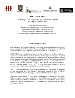
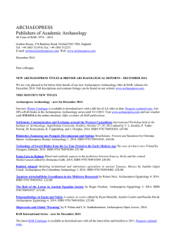
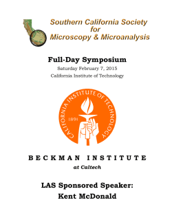
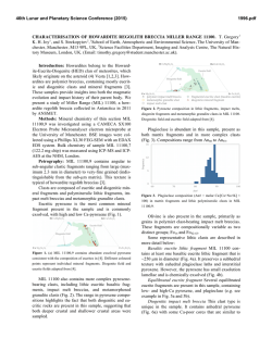
EXPERIMENTAL THREE-DIMENSIONAL PRINTING OF A LOWER PALAEOLITHIC HANDAXE: AN ASSESSMENT OF THE TECHNOLOGY AND ANALYTICAL VALUE BRANDON R. OLSON, JODY M. GORDON, CURTIS RUNNELS AND STEVE CHOMYSZAK Boston University, USA Wentworth Institute of Technology, USA Chipped stone tools are difficult to illustrate in publications with line drawings or analog photographs, and previous attempts to improve on stone tool illustration with stereoviews, coatings, or casts have not been widely adopted by lithic analysts. New software makes it possible to create interactive photorealistic D digital images of stone tools in the field or laboratory without specialized or expensive equipment. These images can be replicated by D printers, and based on our experiments using three different printing media we demonstrate that models printed in ABS plastic are acceptably inexpensive forms that reproduce the artifact features required by specialists. The combination of image-based modeling and D printing will revolutionize the illustration of artifacts and greatly mitigate the need for extensive travel and help alleviate accessibility issues. KEYWORDS: image-based modeling, D printing, digital surrogacy, Palaeolithic handaxe, D photogrammetry New technologies allow archaeological artifacts to be recorded and illustrated with precision in an ethical, non-destructive, and inexpensive manner. Two innovative technologies in particular can be combined to record and duplicate artifacts: image-based D digital modeling and D printing. In the last two years, D modeling software, techniques, and printers have rapidly become cheaper and more user friendly, and the adoption of D technologies in archaeological research has been growing exponentially. This trend is discernible in recent publications. The Journal of Field Archaeology (. []) and the Journal of Eastern Mediterranean Archaeology and Heritage Studies (. and . []) have dedicated entire issues to digital approaches to archaeology, and the Journal of Archaeological Science has experienced a > percent increase in published works focusing on D approaches in archaeology in the last decade (Figure ). Although archaeologists began printing objects created with D laser scanners five years ago (Kuzminsky and Gardiner ; Niven et al. ), the rapid progress of technological developments in D modeling and printing continue to add useful tools to the archaeologist’s expanding digital toolkit. Here we offer the results of our own experiments with image-based photorealistic digital modeling — as © W. S. Maney & Son Ltd DOI: ./Y. opposed to laser scanning — for D printing in archaeology for use in off-site artifact study using three presently-available and industry standard printing media, viz. powder/binder printing, fused deposition modeling, and polyjet printing. THE PROBLEM Efforts to record and illustrate artifacts to make them available for analysis, comparison, and publication most often take the form of two-dimensional analog photographs and illustrations. For years archaeologists have endeavored to add a level of three dimensionality to artifact recordings through the use of shading (Heath ) and stippling in illustrations and the creation of coatings, squeezes, and casts (Rick and White ). With respect to lithic artifacts, efforts to illustrate accurately the form and appearance of chipped stone tools of flint, obsidian, and other siliceous rocks have been ongoing since the mid-nineteenth century when the flaked stone artifacts were first recognized as the artificial products of early human handicraft (Addington : –). Photography has rarely been employed for illustrating stone tools because the reflective surfaces of the rocks that were used to manufacture the tools make it difficult to light Lithic Technology , Vol. No. , – EXPERIMENTAL THREE-DIMENSIONAL PRINTING OF A LOWER PALAEOLITHIC HANDAXE FIGURE . A chart showing the number of articles published in the Journal of Archaeological Science focusing on D approaches in archaeology. The query was made on April , . the specimens adequately to bring out the texture. There is also the problem of the depth of field, which makes it difficult to focus both on the center of sometimes thick, massive stone tools and on the retouched edges in the same photograph. Thus, even in the best two dimensional reflective analog photograph the three dimensional form of the artifact is difficult to perceive or evaluate. These difficulties are obviated, at least partially, by the use of measured technical line drawings that include the outline of the stone tool, the pattern of the scars on the surface left by the removal of flakes in the reduction and retouch stages of artifact manufacture, and the use of radial shading lines in the flake scar outlines to suggest the volume of the artifact and the texture of its surface as they might appear if the artifact was lit obliquely from the upper left (Figure ). The methods and conventions for making two dimensional line drawings were developed by French and English archaeologists in the s, to enable readers to “see” artifacts like the Palaeolithic handaxes that convinced early archaeologists of the antiquity of humans in Europe, e.g., the natural-sized drawings of handaxes found at Hoxne by John Frere in (Daniel : –). The specific conventions used today dispense with most efforts at realistic depictions of the appearance of the artifacts, reducing the images to outlines with flake scar patterns, often accompanied by small arrows and other marks to indicate the technical aspects of flaking such as the presence of negative bulbs of percussion that mark the points Lithic Technology , Vol. No. , – OLSON ET AL. FIGURE . A traditional line drawing of an Acheulean handaxe from the Bosphorus Region of Turkey (Runnels and Özdog˘ an ). It has been slightly edited and is reproduced here courtesy of the President and Trustees of Boston University. where flake detachments were initiated (Shea : –). To this day technical line drawings have been the industry standard for the illustration of lithic artifacts. Although photographs have generally been avoided, cameras and photographers are more readily available than trained lithic illustrators, and there has long been a desire to employ photography to make effective illustrations. Many attempts have been made over the last years to improve the “readability” of photographs, such as coating stone tools with aluminum powder or chalk to reduce the reflectivity of their surfaces, making nonreflective casts of the artifacts to be photographed (Rick and White ), or using stereo photography or holography to capture the three dimensional appearance of the objects, e.g., the stereoviews of handaxes and cleavers from the Lower Palaeolithic site of Olorgesailie in Kenya (Isaac ). These techniques have had limited success and have not been widely adopted. There have been significant improvements in stone tool illustration recently with the introduction of polymer casting and D laser scanning (Grosman et al. ). The polymer casting technique is widely used today for the production of artifact copies for use in teaching, the laboratory, and public display. It is a difficult, costly process that does not lend itself to the publication of such artifacts in print media or online because the casts must again be rendered in line drawings or photographed in order to be reproduced. The Computerized Archaeology Laboratory at The Hebrew University of Jerusalem is currently developing a system to use laser scanning to, among other things, better facilitate quantitative analyses of lithic features, but the technology is still under development (Goren-Inbar ; Grosman et al. , ; Malinsky-Buller et al. ). Any serious study of stone tools requires the lithic specialist to handle the artifacts and examine them in three dimensions under variable lighting conditions. D casts are useful for this purpose, and when made correctly, they allow anyone with the proper technical training to use the cast as a proxy for the actual artifact for most purposes. Unfortunately, trained technicians have to obtain permission and travel to distant locations to gain access to the original artifacts in order to make the necessary molds for the casting, which is often a prohibitive obstacle to the use of this technique. Lithic Technology , Vol. No. , – EXPERIMENTAL THREE-DIMENSIONAL PRINTING OF A LOWER PALAEOLITHIC HANDAXE The inadequacy of most methods of illustration and reproduction of stone tools has led to the demand for a more flexible method to reproduce the physical appearance of stone tools at their natural scale. This need is now being met by the combination of D image-based digital models and D printing. Our successful experiments demonstrate that it is feasible to photograph stone tools in order to make D images that can be viewed on computers and other platforms such as tablets and smartphones. Files with these images can be sent by email and used to print copies of the artifacts on D printers. We believe that the combination of the two techniques, which use commercially available software and hardware and do not require special technical training, can be readily and inexpensively deployed to the field, whether the museum, the laboratory, or the excavation site, allowing the rapid and accurate D imaging and reproduction in a printed format of stone tools in a matter of hours. In our view this is the most significant advance in the illustration of stone tools in over years. THE PROCESS IMAGE-BASED MODELING The use of image-based digital modeling in archaeology is relatively new, though a handful of studies have attested to the technology’s accuracy and utility in archaeological contexts (De Reu et al. , ; Forte ; McCarthy ; Olson et al. ). The recent popularity of the technology, however, has not been matched by a standardized terminology, and a variety of terms have been adopted and published, e.g., photomodeling (Opitz ), structure-from-motion modeling (Green et al. in press); photogrammetry (Quartermaine et al. ); computational photography (Rabinowitz ); and image-based modeling (Olson and Placchetti ; Remondino ). For the sake of clarity and consistency we adopt the term “image-based modeling” to include the methods, software programs, and specific algorithms that extract spatial information from images to generate D data (point clouds, tin grids, monochromatic models, photorealistic textured models, etc.). There are a number of software programs that utilize an image-based approach, including newly developed open source options (Green et al. in press), but because of the affordability, ease of use, and quality outputs, we used Agisoft PhotoScan to model a Lower Palaeolithic handaxe for our experiments (Figure ). FIGURE . A cutaway of a D model created using an imagebased modeling approach showing (A) the point cloud; (B) the untextured model; (C) the textured model. The figure was designed and created by Ryan A. Placchetti and Brandon R. Olson. To model the handaxe three dimensionally, we took photographs at five different angles of capture using a tripod and a rotatable surface, an effective photographic method that has been tested previously (Olson et al. ). Accurate D models are possible so long as the surface of the object is completely photographed and there Lithic Technology , Vol. No. , – OLSON ET AL. is at least percent overlap in successive photographs. The Lower Palaeolithic handaxe was photographed for this study with an MP Canon Rebel Ti digital SLR camera with an – mm lens. The photos were loaded into PhotoScan to generate a tessellated D point cloud, then a dense point cloud, a monochromatic D model, and finally a fully photorealistic textured model (Figure ; attached D model). The textured model was exported as an .obj file and downloaded into Meshlab for scaling and conversion to an .stl file for printing. D PRINTING With the assistance of the Manufacturing Center at Wentworth Institute of Technology (WIT) in Boston, we printed the handaxe using three types of D printers (powder [Figure B], ABS plastic [Figure C], and resin [Figure D]). WIT currently has three D printers located in the D Print Lab within WIT’s Manufacturing Center: Powder/ Binder Printing utilizing a ZCorp Plus printer and ZPrint software (henceforth powder), Fused Deposition Modeling utilizing a uPrint D Printer and Catalyst EX software (henceforth plastic), and PolyJet Printing utilizing an OBJET printer and OBJET Studio software (henceforth resin). Each printer utilizes a different printing technology to build three-dimensional parts using a layered additive process. Each printer requires a computational model in .stl (standard tessellation language) format that embodies the D geometry of the object to be printed. The printing process requires preparation of the print files, monitoring/replacing print materials, routine printer maintenance, initiation of the print, removal of the print from the printer, and typically some form of postprocessing. The entire printing process can take anywhere from minutes to days depending on the object size, printing resolution, printing speed, and postprocessing. With the assistance of Mechanical Engineering and the D Printing Lab at Wentworth Institute of Technology in Boston, we printed copies of the handaxe with all three D printers (Figure ). POWDER PRINTING Powder printing follows a process whereby a thin layer of powder is adhered to previous layers using a binder system that is sprayed through a liquid jet printing head. The binder reacts with the powder to transform it from a “dry” state into a “green” state, meaning that the powder is stuck together, but is still somewhat fragile. To fortify the green powder print, a Magnesium Sulfate solution is often applied to create a thin protective crust. Alternatively the print can also be infiltrated with Cyanoacrylate or a low viscosity two-part epoxy, FIGURE . The printed Acheulean handaxe in the following forms (A) the original artifact; (B) the powder print; (C) the plastic print; (D) the resin print. Lithic Technology , Vol. No. , – EXPERIMENTAL THREE-DIMENSIONAL PRINTING OF A LOWER PALAEOLITHIC HANDAXE either of which adds significant strength to the object and, once infiltrated, the object can be painted if desired. The printer — the ZCorp Plus — is capable of creating layers as thin as . mm and can produce relatively fine detailed prints within a × × mm build volume. An advantage of powder printing is that all object surfaces are well supported by the dry powder, which reduces the need for additional object support and raft considerations inherent in plastic and resin printing. Such an attribute allows many objects to be printed within the D build volume of the printer during one continuous print session, which greatly increases productivity. While the level of detail possible with powder printing is relatively fine, increased detail can result in increased object fragility, especially during infiltration because of manual handling during the excavation of the object from the printer, the removal of excess powder from the print via a de-powdering process involving a small stream of compressed air, and the final post-processing. PLASTIC PRINTING Plastic printing uses a heated nozzle to melt a filament of material that is deposited one layer at a time to construct the object. The heated material fuses to a previously deposited layer. The temperature of the nozzle and the speed at which it moves are functions of the type of material being printed. There are numerous polymer options including Nylon, Polycarbonate, Polylactic Acid (PLA), Ultem, PET, and ABS plastic. The uPrint D Printer tested here is a Fused Deposition Modeling (FDM) option that uses a proprietary form of ABS plastic. It is capable of printing in layer heights of . mm within a build volume of × × mm. Due to the nature of FDM printing, parts with overhanging features require support to prevent drooping during the deposition and cooling process. The Catalyst EX software used with the printer automatically calculates where the support material needs to be added and adds the support features to the printed model. In the case of the uPrint, the support material is not ABS plastic, but a dissolvable plastic that is printed using a second heated nozzle. It is easily dissolved in a heated sodium hydroxide bath during post-processing. Parts made with ABS plastic are less fragile than powder prints and can be used immediately after the support material is dissolved. It is even possible to print pre-assembled parts that are operable so long as proper clearances between moving parts are designed into the assembly prior to printing. Objects printed in plastic are not as strong as those created using injection molding, which is a common mass manufacturing method of creating plastic parts, because the FDM process essentially laminates (fuses) one layer of melted plastic onto another. The fusing process does not provide the same level of strength that would be found in a molded part where the printing medium fills a mold cavity while in a molten state and the entire part subsequently cools to a uniform temperature. This means that — at times — there are certain utility considerations one must contemplate when determining how to best orient the digital object within the build volume prior to printing. RESIN PRINTING Resin printing uses a print head to spray a thin layer of photocurable resin. Each layer of liquid resin is converted into a solid by exposure to ultraviolet light. The benefit of this process is that it is fast and can produce durable parts with great detail and there are numerous resins with different properties ranging from rigid plastic to flexible rubber-like materials. As with plastic printing, resin printing also requires a support system for overhanging features. The support system is built using a second photocurable resin that is easily removed with a fine, high-pressure water jet. The resin printer used for this test, an OBJET , is capable of creating layers as thin as . mm within a × × mm build volume. COSTS In the end, it took approximately hours to fully model the Acheulean handaxe with an imagebased modeling technique, and, depending on the desired printing method, up to seven hours for each print. From the perspective of cost, the modeling of the objects required a digital SLR camera, a tripod, and a license of PhotoScan ($ USD with the educational discount). The cost of D printing at WIT’s Manufacturing Center is based solely on the cost of the materials used in each of the printers, a nominal administrative markup, and state sales tax. The cost of each print is estimated by the volume of printing material consumed, multiplied by the material’s price per unit volume, which translated into the following prices: powder ($. USD), plastic ($. USD), and resin ($. USD). It must be noted that one would encounter different pricing points in a commercial setting. Figure depicts an Lithic Technology , Vol. No. , – OLSON ET AL. FIGURE . A chart depicting an approximate normalized material price range per cubic millimeter for each printing media. approximate normalized material price range per cu mm for each of the three printers. AN ASSESSMENT OF PRINTING TECHNOLOGIES The principal use of printed D models of stone tools will be for exhibition, teaching, and the comparison of specimens from different collections. D models would permit colleagues, students, and members of the public to evaluate the size, volume, and appearance of artifacts with which they have had little or no prior experience, or where original specimens are unavailable. For lithic technologists, on the other hand, the classification, measurement, publication, and comparison of artifacts from different assemblages may still be accomplished most economically by using conventional imagery supplemented with the use of D digital images that can be viewed, manipulated, and transmitted easily on electronic platforms using commercially available software. In some cases printed D models may be useful also for analytical purposes. The form or the patterning of the flake scars on stone tools may be difficult to see in photographs or to depict in conventional line drawings because the raw materials are highly reflective like milky quartz, or have coarse, grainy, and irregular surfaces like quartzites or hydrothermally altered silicates. In such circumstances, even D digital models viewed on computer screens, typically at a resolution of dpi, will suffer a significant loss of visual detail and be difficult for the analyst to “read.” Printed models show features that might otherwise be hard to see in drawings or photographs. They would also allow tactile examination, such as putting one’s fingers in the negative bulbs of percussion to find the places on the edge of the tool where the flake scars originated, or to trace shallow and indistinct edges of flake scars on the face of the artifact. This sort of examination could be particularly helpful in cases where the surface of the stone tool is difficult to see, or where the artifactual nature of the specimen might be at issue. Our experience has shown that in these cases it is best to handle the artifact directly, and where this is not possible, the printed D model may be the next best thing. How well do the D printed models serve for the study of stone tools by lithic analysts? And how do the different media of reproduction (powder, plastic, resin) affect the readability of the artifacts being printed? To answer these questions we selected a Lower Palaeolithic handaxe from the French site of St. Acheul for modeling and printing in all three materials for comparative purposes (Figures and ). The handaxe is from the Gabel Museum of Archaeology in the Department of Archaeology at Boston University and is a typical specimen of the Acheulean Industrial Tradition. It may be as much as , years in age and is made of greenish brown flint (chert) of local origin and has a heavily patinated or weathered surface. QUALITATIVE COMPARISON As part of their examination of such an artifact, lithic analysts study the form of a stone tool in order to describe and classify it correctly in terms of the size, shape, and the placement of retouch, among other attributes, that tend to vary from culture to culture and period to period (for a full discussion of this process, see Shea : –, especially –). Part of this examination involves the study of the flaking process that was employed to shape the artifact. The different methods of production and shaping produce different patterns of flake scars on the surface of the artifact, and the flake scars that result from the removal of flakes by direct percussion with a hammerstone or a soft hammer such as deer antler are shallow conchoidal impressions. As flaking proceeds, the flake scars may overlap in a parallel or sub-parallel series on the surface of the finished artifact. The lithic Lithic Technology , Vol. No. , – EXPERIMENTAL THREE-DIMENSIONAL PRINTING OF A LOWER PALAEOLITHIC HANDAXE analyst must be able to see these patterns of flake removals, and the shape, depth, and size of the flake scars must be visible to permit the analyst to correctly describe and classify the object. For this purpose, the model printed in powder was the least acceptable. Because we did not want to lose minute surface details, we decided to forgo infiltration. On the one hand, subtle surface changes were not obscured by the infiltration process, but on the other hand the printed object had a dull chalky surface with a grainy rough texture. Not only does the material come off on one’s hands, it is also difficult to see the finer flake scars on its surface. The only advantage of using this material was its low cost. The printed models would be useful only for display or rough handling in the classroom where expendable but cheap copies are desirable. The resin model was of superior quality. It weighs more, giving the model the look and feel of an actual stone tool (albeit white in color, something that could be corrected by using a color printer or hand tinting). The flake scars are clearly visible on the surface of the model, and the patterning, size, and individual physical characteristics of the flake removals can be readily discerned as the model is examined in raking light. The surface reflects more light than the powder model and has the same properties visually as found in the stone original. The resin surface was more reflective, however, than both of the other models, which tended to make it difficult to define the boundaries, or edges, of the flake scars. We found that it was more difficult to see the surface detail under fluorescent lighting, which washed out the surface by neutralizing the reflectivity of the material. Natural light or incandescent lighting was superior for examining the surface. Models in this material are more expensive to print than those in the other media, but they might be the best choice for use in displays. The plastic models appear to be the most useful for analytical purposes. The surface resolution of detail is as good as that in the resin models, and the cost of printing is significantly lower. There are drawbacks to using plastic as a medium: the models are lighter in weight than the resin print (though, as with the resin, the print weight can be increased to better approximate the actual artifact), and thus do not feel as much like stone as the others. The printing process also tends to build the plastic up in layers that leave a surface texture with a distinctly visible striped or moiré pattern. This texture can be distracting to the eye. Fortunately, this layered texture does not interfere with the general readability of the flake removals and surface details of the artifact because the surface reflects light in much the same way as noted on the resin models. The plastic model had a crisp resolution of the boundaries and edges of the flake scars. QUANTITATIVE COMPARISON Powder printing is not an ideal medium for artifact analysis because of its fragility. As noted, to strengthen a powder print, the object is often infiltrated with a Magnesium Sulfate solution, Cyanoacrylate, or a low viscosity two-part epoxy, which create a protective crust that can obscure subtle surface details. If not infiltrated, the print deteriorates during handling. Owing to these factors and those points raised in the qualitative comparison, we offer here a quantitative comparison of only the plastic and resin prints. In theory one would expect the resin handaxe to maintain and present more surface detail than the plastic form because it was printed at a higher resolution (an optimal layer thickness of . mm versus . mm for the plastic, a percent difference). The combination of the thinner layers and the viscosity of the liquid resin, however, produce a smoothing effect during printing. The smoothing effect is a result of minute surface displacement of each liquid resin layer prior to its exposure to ultraviolet light. This smoothing takes place during printing and produces a semireflective sheen on the printed object, which slightly hinders the readability of the artifact in certain lighting conditions. After exporting D models of the plastic and resin prints as two dimensional raster grids and comparing , contiguous pixel values along the same linear path, the difference between both printing media became apparent (Figure ). Figure B depicts the pixel values in centimeters for each object along the paths shown in Figure A. The fact that the pixel values for the plastic print are consistently higher than those of the resin print is unimportant because the difference could just as easily be attributed to photographic capturing conditions as to differences in the media used to print the two models. What is noteworthy, however, is the variability among pixel values within the object, which is visible when one compares the rigidity of the line representing values of the plastic model (upper line in Figure B) to the smoother line depicting resin pixel values (lower line in Figure B). Furthermore, the average difference in values of the same group of contiguous pixels for the plastic print is . µm, while the average Lithic Technology , Vol. No. , – OLSON ET AL. FIGURE . A comparison of , contiguous pixel values for two D prints: (A) the line of pixels queried for the plastic (left) and resin (right) prints; (B) a line graph showing the intensity and variability of pixel values in centimeters for both prints. Lithic Technology , Vol. No. , – EXPERIMENTAL THREE-DIMENSIONAL PRINTING OF A LOWER PALAEOLITHIC HANDAXE for the resin print is . µm. Therefore, the lessrigid contours of the line representing the resin print (Figure B) and the smaller average difference between contiguous pixel values (. µm versus . µm) demonstrates that smoothing occurs by way of liquid resin displacement during the printing process and prior to hardening. The higher viscosity of the ABS plastic prevents such a smoothing effect. Although the smoothing only subtly affects the preservation of topographic variation and nuance of the printed model, the semi-reflective surface hinders the readability of the object. In sum, we found that both plastic and resin work well for printing stone tools models that are adequate for teaching, display, and laboratory analysis. The choice of resin over plastic may be a function of the unit cost of printing models and the special needs of the specialist, but we are confident that the plastic models are the best for most purposes, while the resin models are best reserved for special purposes such as public display and handling for non-analytic purposes. CONCLUSIONS In an attempt to define the new interest and implementation of D workflows in all facets of archaeology (planning, practice, documentation, and dissemination), Rabinowitz cogently characterized the movement as the “age of digital surrogacy” (Rabinowitz ). A digital surrogate is simply a faithful digital representation of an original or more specifically for our purpose here, the digital outputs (point cloud, dense point cloud, tin grid, georeferenced orthorectified photos, monochromatic D models, textured D models, etc.) of an imagebased modeling workflow. What remains unclear, however, is the relationship between the artifact and the digital surrogate, and in our case the D print of the digital surrogate. We are convinced that the photorealistic models and D printings are informative renderings that are superior to line illustrations in detail, and superior to casts in their ability to be digitally transmitted and transferred. It is clear that certain D printing formats retain minute lithic characteristics. The powder model, unless immersed in a durable coating, is too fragile for continued handling. Although the plastic model retains faint horizontal lines, which are byproducts of printing, it retained the physical characteristics of the stone artifact that a lithicist needs to see in a reproduction, while the resin model best approximates the original in physical weight and feel, but at a modest loss in readability. This entire process suggests that the combination of inexpensive image-based modeling and printing could revolutionize existing modes of archaeological analysis, dissemination, and education. This combination of techniques makes it possible for an archaeologist with little training to obtain a digital camera, photograph an object, process the images in a readily-available and easy-to-use commercial modeling software, print realistic D models, and email the D models to others. And it can be done in a day’s work. The process also mitigates the need for extensive travel and artifact accessibility issues after the object has been modeled and printed. Three dimensional imagebased modeling and printing are revolutionary, bringing the technology of the Stone Age to life and for the first time, the technology helps solve a -year old problem of lithic illustration. ACKNOWLEDGEMENTS We would like to thank the Department of Archaeology at Boston University and the College of Arts and Sciences, as well as the Manufacturing Center, at Wentworth Institute of Technology for the use of their resources. The Chad DiGregorio Grant-in-Aid Fund at Boston University supported this study, for which we are grateful. REFERENCES Addington, L. R. Lithic Illustration: Drawing Flaked Stone Artifacts for Publication. University of Chicago Press, Chicago. Daniel, G. A Short History of Archaeology. Thames and Hudson, London. De Reu, J., P. De Smedt, D. Herremans, M. Van Meirvenne, P. Laloo, and W. De Clercq On Introducing an Image-Based D Reconstruction Method in Archaeological Excavation Practice. Journal of Archaeological Science : –. De Reu, J., G. Plets, G. Verhoeven, P. De Smedt, M. Bats, B. Cherretté, W. De Maeyer, J. Deconynck, D. Herremans, P. Laloo, M. Van Meirvenne, and W. De Clercq Towards a Three-Dimensional Cost-Effective Registration of the Archaeological Heritage. Journal of Archaeological Science : –. Forte, M. D Archaeology: New Perspectives and Challenges — The Example of Çatalhöyuk. Journal of Eastern Mediterranean Archaeology and Heritage Studies : –. Goren-Inbar, N. Culture and Cognition in the Acheulian Industry: A Case Study from Gesher Benot Ya’aqov. Philosophical Transactions of the Royal Society B: Biological Sciences : –. Green, S., A. Bevan, and M. Shapland A Comparative Assessment of Structure from Motion Methods for Archaeological Research. Journal of Archaeological Science : –. Lithic Technology , Vol. No. , – OLSON ET AL. Grosman, L., A. Karasik, O. Harush, and U. Smilansky Archaeology in Three Dimensions: Computer-Based Methods in Archaeological Research. Journal of Eastern Mediterranean Archaeology and Heritage Studies : –. Grosman, L., O. Smikt, and U. Smilansky On the Application of -D Scanning Technology for the Documentation and Typology of Lithic Artifacts. Journal of Archaeological Science : –. Heath, S. Closing Gaps with Low-Cost D. The Archaeology of the Mediterranean World. <http://mediter raneanworld.wordpress.com////closing-gapswith-low-cost-d/>. Isaac, G. L. Olorgesailie: Archeological Studies of a Middle Pleistocene Lake Basin in Kenya. University of Chicago Press, Chicago. Kuzminsky, S. C., and M. S. Gardiner Three-Dimensional Laser Scanning: Potential Uses for Museum Conservation and Scientific Research. Journal of Archaeological Science : –. Malinsky-Buller, A., L. Grosman, and O. Marder A Case of Techno-Typological Lithic Variability & Continuity in the Late Lower Palaeolithic. Before Farming /: –. McCarthy, J. Multi-Image Photogrammetry as a Practical Tool for Cultural Heritage Survey and Community Engagement. Journal of Archaeological Science : –. Niven, L., T. E. Steele, H. Finke, T. Gernat, and J.-J. Hublin Virtual Skeletons: Using a Structured Light Scanner to Create a D Faunal Comparative Collection. Journal of Archaeological Science : –. Olson, B. R., and R. A. Placchetti A Discussion of the Analytical Benefits of Image-Based D Modeling in Archaeology. The Archaeology of the Mediterranean World. <http://mediterraneanworld.wordpress.com/ ///a-discussion-of-the-analytical-benefits-of-imagebased-d-modeling-in-archaeology/>. Olson, B. R., R. A. Placchetti, J. Quartermaine, and A. E. Killebrew The Tel Akko Total Archaeology Project (Akko, Israel): Assessing the Suitability of Multi-Scale D Field Recording in Archaeology. Journal of Field Archaeology : –. Opitz, R. Three Dimensional Field Recording in Archaeology: An Example from Gabii. The Archaeology of the Mediterranean World. <http://mediterranean world.wordpress.com////three-dimensional-fieldrecording-in-archaeology-an-example-from-gabii/>. Quartermaine, J., B. R. Olson, and M. Howland Using Photogrammetry and Geographic Information Systems (GIS) to Draft Accurate Plans of Qazion. Journal of Eastern Mediterranean Archaeology and Heritage Studies : –. Rabinowitz, A. The Work of Archaeology in the Age of Digital Surrogacy. The Archaeology of the Mediterranean World. <http://mediterraneanworld.wordpress.com/ ///the-work-of-archaeology-in-the-age-of-digitalsurrogacy/>. Remondino, F. Worth a Thousand WordsPhotogrammetry for Archaeological D Surveying. In Interpreting Archaeological Topography: D Data, Visualisation, and Observation, edited by R. S. Opitz, and D. C. Cowley, pp. –, Occasional Publications of the Aerial Archaeology Research Group .Oxbow, Oxford. Rick, J. W., and T. D. White Photography of Obsidian Artifacts: A Useful Alternative. Newsletter of Lithic Technology (): . Runnels, C., and M. Özdog˘ an The Palaeolithic of the Bosphorus Region, NW Turkey. Journal of Field Archaeology : –. Shea, J. Stone Tools in the Paleolithic and Neolithic Near East. Cambridge University Press, Cambridge. NOTES ON CONTRIBUTORS Brandon R. Olson is a Ph.D. Candidate in the Department of Archaeology at Boston University. A classical archaeologist, he has worked extensively in Cyprus, Turkey, and Israel. He specializes in the Hellenistic and Roman worlds, as well as Geographic Information Systems and D modeling in archaeology. Correspondence to: Brandon R. Olson, Department of Archaeology, Boston University, Commonwealth Avenue, Boston, MA U.S.A. Email: [email protected] Jody Michael Gordon is an Assistant Professor of Humanities and Social Sciences at Wentworth Institute of Technology in Boston where he teaches classes on ancient history, art, and architecture. He received his Ph.D. in classical archaeology from the Department of Classics at the University of Cincinnati and he is an Assistant Director of the Athienou Archaeological Project in the Republic of Cyprus. Correspondence to: Jody Michael Gordon, Department of Humanities and Social Sciences, Wentworth Institute of Technology, Huntington Ave. Boston, MA , U.S.A. Email: gordonj@wit.edu Curtis Runnels is Professor of Archaeology in the Department of Archaeology at Boston University. He specializes in Aegean prehistory from the Palaeolithic to the Neolithic, and his recent research focuses on site location models for Mesolithic and Palaeolithic sites. He is currently engaged in the study of the Palaeolithic from Crete. Correspondence to: Curtis Runnels, Department of Archaeology, Boston University, Commonwealth Avenue, Suite EBoston, MA , U.S.A. Email: [email protected] Steve Chomyszak is an Assistant Professor of Mechanical Engineering and Technology at Wentworth Institute of Technology in Boston. He is a specialist in D printing and has taught a variety of classes in the Engineering Center at Wentworth. Correspondence to: Steve Chomyszak, Mechanical Engineering Wentworth, Institute of Technology, Huntington Ave. Boston, MA , U.S.A. Email: [email protected] Lithic Technology , Vol. No. , –


© Copyright 2026