
Technical Information RID14
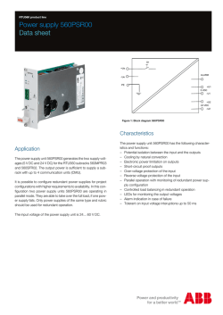
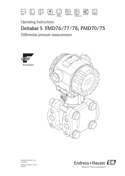
TI00145R/09/EN/13.13 71232470 Products Solutions Services Technical Information RID14 8-channel field indicator with FOUNDATION Fieldbus™ or PROFIBUS® PA protocol Field indicator for easy integration into existing fieldbus systems Application • Field indicator with 8 input channels and FOUNDATION Fieldbus™ or PROFIBUS® PA protocol for displaying process values and calculated values • Also optionally available for Ex d applications • Onsite display of process parameters in fieldbus systems Your benefits • Bright, backlit LC indicator with bar graph, diagnostic symbols and plain text field • Listener mode for up to 8 analog channels or digital statuses • 8-channel indicator via function block interconnection in the case of FOUNDATION Fieldbus™ • Safe operation in hazardous areas thanks to international approvals such as – FM IS, NI – CSA IS, NI – ATEX Ex ia, Ex nA for intrinsically safe installation in zone 1 and zone 2 • Aluminum housing or optional stainless steel housing RID14 Function and system design Measuring principle Backlit display for up to 8 process values or calculated values of the fieldbus users connected to the fieldbus system via listener mode, or also via function block interconnection in the case of FOUNDATION Fieldbus™. Measuring system Endress+Hauser has a wide range of innovative products which can be used with the FOUNDATION Fieldbus™ and PROFIBUS® PA protocol. Together with the sensors and transmitters, the indicators form a complete measuring point for various applications in the industrial sector. Device architecture Field controller Visualization and monitoring e. g. P View, FieldCare and diagnostic software High speed Ethernet (HSE) 100 Mbit/s H1 31.25 kbit/s Linking Device Linking Device Linking Device H1 IEC 61158-2 H1 FISCO 0 - 10 bar 0 - 10 bar RID16 RID14 up to 32 devices per segment A0011300-EN System integration via FOUNDATION Fieldbus™ PLC Visualization and monitoring e. g. P View, FieldCare and diagnostic software PROFIBUS-DP PROFIBUS-PA IEC 61158-2 31.25 kbit/s segment coupler segment coupler segment coupler FISCO 0 - 10 bar 0 - 10 bar RID16 RID14 Up to 32 devices per segment A0021436-EN System integration via PROFIBUS® PA 2 Endress+Hauser RID14 The 8-channel indicator displays the measured values, calculated values and status information of the fieldbus users in a fieldbus network. In the listener mode, the device listens to the set fieldbus addresses and displays their specific values. Furthermore, values available on the bus can be also displayed via function block interconnection in the case of a FOUNDATION Fieldbus™ indicator. Individual settings can be made for each channel. Analog values from the bus user are displayed as a five-digit number while digital values are displayed as plain text (ON/OFF, OPEN/CLOSE, numerical values). The process value status is indicated by icons or as plain text on the measured value display. Plain text display makes it possible to display alphanumeric character combinations, such as the TAG. For trend analysis, in addition to indicating measured values the indicator also has a bar graph, with indicators for overranging and underranging, which can be scaled independently of the display value. The device is powered by the fieldbus and can be used in hazardous areas up to temperature class T6. Communication and data processing Breakdown information • Status message as per the fieldbus specification. Switch-on delay • 8s FOUNDATION Fieldbus™ • • • • • FOUNDATION Fieldbus™ H1, IEC 61158-2 FDE (Fault Disconnection Electronic) = 0 mA Data transmission rate: supported baud rate = 31.25 kBit/s Signal coding = Manchester II LAS (link active scheduler), LM (link master) function is supported: Thus, the indicator unit can assume the function of a link active scheduler (LAS) if the current link master (LM) is no longer available. The device is supplied as a BASIC device. To use the device as an LAS, this must be defined in the distributed control system and activated by downloading the configuration to the device. • In accordance with IEC 60079-27, FISCO/FNICO PROFIBUS® PA • • • • • PROFIBUS® PA in accordance with EN 50170 Volume 2, IEC 61158-2 (MBP) FDE (Fault Disconnection Electronic) = 0 mA Data transmission rate: supported baud rate = 31.25 kBit/s Signal coding = Manchester II Connection data in accordance with IEC 60079-11 FISCO, Entity Protocol-specific data FOUNDATION Fieldbus™ Basic data Device type 10CF (hex) Device revision 01 (hex) Node Address Default: 247 ITK version 5.2.0 ITK Certification Driver No. IT064000 Link Master-capable (LAS) Yes Link Master / Basic Device selectable Yes; factory setting: Basic Device Number of VCRs 58 Number of Link Objects in VFD 64 Virtual communication relationships (VCRs) Endress+Hauser Permanent Entries 58 Client VCRs 0 Server VCRs 5 Source VCRs 8 Sink VCRs 0 3 RID14 Subscriber VCRs 35 Publisher VCRs 10 Link settings Slot time 4 Min. inter PDU delay 12 Max. response delay 40 Blocks Block description Block index Permanent Resource Display Transducer Advanced Diagnostic PID Input Selector 1 Input Selector 2 Arithmetic Integrator 400 500 600 700 800 900 1000 1100 YES YES YES NO NO NO NO NO Block execution time 100 ms 35 ms 35 ms 50 ms 60 ms Block class Extended Manufacturer-specific Manufacturer-specific Standard Standard Standard Standard Standard Brief description of the blocks Resource Block: The Resource Block contains all the data that clearly identify and characterize the device. It is like an electronic device nameplate. In addition to parameters that are needed to operate the device on the fieldbus, the Resource Block also makes other information available, such as the order code, device ID, software revision, order ID etc. Display Transducer: The parameters of the "Display" Transducer Block allow the configuration of the display. Advanced Diagnostic: All the parameters for automatic monitoring and diagnosis are grouped together in this Transducer Block. PID: This function block contains input channel processing, proportional integral-differential control (PID) and analog output channel processing. The following can be implemented: basic controls, feedforward control, cascade control and cascade control with limiting. Input Selector (ISEL): The block for selecting a signal (Input Selector Block - ISEL) allows the user to choose up to four inputs and generates an output based on the configured action. Integrator (INT): The Integrator Block integrates one or two variables over time. The Block compares the integrated or totalized value to limit values and generates a discrete output signal if the limit value is reached. It can be selected from six integration types. Arithmetic (ARITH): The Arithmetic function block permits standard computing operations and compensations. It supports the addition, subtraction, multiplication and division of values. Furthermore, mean values are calculated, and flow values are compensated (linear, quadratic compensation), in this block. PROFIBUS® PA Basic data Indicator for PROFIBUS PA, can be used in conjunction with PROFILE 2 and PROFILE 3 (3.0, 3.01 and 3.02) devices Device master files (GSD) How to acquire device master files (GSD) and device drivers: • FieldCare/DTM: www.endress.com → Select country → Solutions → Field Network Engineering → Fieldbus device integration → PROFIBUS → PROFIBUS® GSD files and certificates Write protection 4 Write protection enabled by hardware setting (DIP switch) Endress+Hauser RID14 Power supply Electrical connection A0021528 Terminal assignment of the field indicator 1 FOUNDATION Fieldbus™ or PROFIBUS® PA Supply voltage Voltage is supplied via the fieldbus. U = 9 to 32 V DC, polarity-independent (max. voltage Ub = 35 V). Mains voltage filter 50/60 Hz Current consumption 11 mA Cable entry The following cable entries are available: • • • • • Thread NPT1/2 Thread M20 Thread G1/2 2x gland NPT1/2 + 1x dummy plug 2x gland M20 + 1 x dummy plug Installation Installation instructions Mounting location Wall or pipe mounting (see 'Accessories') Orientation No restrictions, the orientation depends on the readability of the display. Environment Ambient temperature limits -40 to +80 °C (-40 to 176 °F) The display can react slowly at temperatures < -20 °C (-4 °F). The readability of the display is no longer guaranteed at temperatures < -30 °C (-22 °F). Storage temperature -40 to +80 °C (-40 to 176 °F) Altitude Up to 4000 m (13100 ft.) above mean sea level in accordance with IEC 61010-1, CSA 1010.1-92 Climate class According to IEC 60654-1, Class C Endress+Hauser 5 RID14 Humidity • Condensation permitted as per IEC 60 068-2-33 • Max. rel. humidity: 95% as per IEC 60068-2-30 Degree of protection IP67. NEMA 4X. Shock and vibration resistance 10 to 2000 Hz for 5g as per IEC 60 068-2-6 Electromagnetic compatibility (EMC) CE EMC conformity The device complies with all the requirements of IEC 61326-1:2006 and NAMUR NE21:2007. This recommendation is a consistent determination as to whether the devices used in laboratories and in distributed control systems are immune to interference, thus increasing their functional safety. ESD (electrostatic discharge) IEC 61000-4-2 6 kV cont., 8 kV air Electromagnetic fields IEC 61000-4-3 0.08 to 4 GHz Burst (fast transients) IEC 61000-4-4 1 kV Surge IEC 61000-4-5 1 kV asym. Conducted RF IEC 61000-4-6 0.01 to 80 MHz 10 V/m 10 V Measuring category Measuring category II as per IEC 61010-1. The measuring category is provided for measuring on power circuits that are directly connected electrically with the low-voltage network. Degree of contamination Pollution degree 2 as per IEC 61010-1. Mechanical construction Design, dimensions Die-cast aluminum housing for general applications, or optional stainless steel housing A0011152 Dimensions of the field indicator; dimensions in mm (in) • Aluminum housing for general applications, or optional stainless steel housing • Electronics compartment and terminal compartment together in the single-chamber housing • Display pluggable in 90° stages Weight 6 • Approx. 1.6 kg/3.5 lb (aluminum housing) • Approx. 4.2 kg/9.3 lb (stainless steel housing) Endress+Hauser RID14 Material Terminals Housing Nameplate Die-cast aluminum AlSi10Mg with powder coating on polyester base Aluminum AlMgl, black anodized Stainless steel 1.4435 (AISI 316L), optional 1.4301 (AISI 304) Screw terminals for cables up to max. 2.5 mm2 (14 AWG) plus ferrule Human interface Display elements A0011307 LC display of the field indicator (backlit, pluggable in 90° stages) Item 1: bar graph display in increments of 10% with indicators for underranging (item 1a) and overranging (item 1b) Item 2: measured value display, digit height 20.5 mm (0.8"), status indication "Bad measured value status" Item 3: 14-segment display for units and messages Item 4: 'Communication' symbol Item 5: 'Parameters cannot be modified' symbol Item 6: '%' unit Item 7: 'Uncertain measured value status' symbol • Display range -9999 to +99999 Configuration FOUNDATION Fieldbus™ The configuration of FOUNDATION Fieldbus™ functions and of device-specific parameters is performed via fieldbus communication. Special configuration systems provided by various manufacturers are available for this purpose. Distributed control systems Asset management systems Endress+Hauser ControlCare National Instruments NI-Configurator ( 3.1.1) Emerson DeltaV Emerson AMS and Handheld FC375 Rockwell Control Logix/FFLD - Honeywell PKS Experion - Yokogawa Centum CS3000 - PROFIBUS® PA The parameters can either be configured remotely via the DTM and configuration software or locally via DIP switches. Endress+Hauser 7 RID14 Certificates and approvals CE mark The device meets the legal requirements of the EC directives. Endress+Hauser confirms that the device has been successfully tested by applying the CE mark. Ex-approval Information about currently available Ex versions (ATEX, FM, CSA, etc.) can be supplied by your E+H Sales Center on request. All explosion protection data are given in a separate documentation which is available upon request. Other standards and guidelines • IEC 60529: Degrees of protection provided by enclosures (IP code) • IEC 61010-1: Safety requirements for electrical equipment for measurement, control and laboratory use • IEC 61326 series: Electromagnetic compatibility (EMC requirements) • NAMUR: International user association of automation technology in process industries (www.namur.de) Equipment safety UL Recognized component to UL61010-1 CSA GP CSA General Purpose 8 Endress+Hauser RID14 Ordering information Detailed ordering information is available from the following sources: • In the Product Configurator on the Endress+Hauser website: www.endress.com → Select country → Instruments→ Select device → Product page function: Configure this product • From your Endress+Hauser Sales Center: www.endress.com/worldwide Product Configurator - the tool for individual product configuration • Up-to-the-minute configuration data • Depending on the device: Direct input of measuring point-specific information such as measuring range or operating language • Automatic verification of exclusion criteria • Automatic creation of the order code and its breakdown in PDF or Excel output format • Ability to order directly in the Endress+Hauser Online Shop Accessories Various accessories are available for the device, and these can be ordered with the device or at a later stage from Endress+Hauser. Detailed information on the order code in question is available from your local Endress+Hauser Sales Center or on the product page of the Endress+Hauser website: www.endress.com. Device-specific accessories Communication-specific accessories Designation Type Pipe mounting kit Mounting bracket, pipe 2", 316L Designation Type Fieldbus connector FOUNDATION Fieldbus™ • M20 7/8" PROFIBUS® PA • NPT ½" M12 • M20 M12 • M20 7/8" Interface cable Commubox FXA291 incl. FieldCare Device Setup + DTM Library Documentation • Overview brochure: System Components and Data Managers - Solutions for a Complete Measuring Point: FA00016K/09 • Operating Instructions 'Field indicator RID14 with FOUNDATION Fieldbus™ protocol': BA00282R/09 • Operating Instructions 'Field indicator RID14 with PROFIBUS® PA protocol': BA01267K/09 • ATEX Safety instructions: – ATEX II1G Ex ia IIC: XA00096R/09 – ATEX II2G Ex d IIC: XA00097R/09 – ATEX II2D Ex tD A21: XA00098R/09 – Ex nA, Ex nL: XA01001K/09 Endress+Hauser 9 www.addresses.endress.com


© Copyright 2026