
Wärtsilä Low Loss Concept (LLC) explained
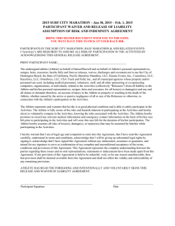
WARTSILA LLC SYSTEM EXPLAINED 1. Introduction - History 2 • Wartsilas origins for Electrical and Automation Systems, starts in the 1970s with the supply of electrical distribution to vessels & platforms in the North Sea. • During the 1990s, vessels operating in the oilfields needed capability for maintaining position with a high degree of accuracy. This in turn increased the demand for thrusters driven by electric motors and as a consequence, operators started to move away from vessels with conventional diesel mechanical propulsion towards diesel electric ones where propulsion engines were displaced by diesel gensets delivering the power to the thruster & vessel hotel load. • The control of the electric motor is done by a device called a Variable Frequency Drive which controls both frequency and voltage. Thanks to this, both the speed and the power of the motor can be controlled. • To meet such requirements,specifically for the Marine / Oil and Gas market, Wartsila developed their own range of Low Voltage Variable Frequency Drives starting from 800 kWe going up to 5500 kWe. • These drives are avialable in 2 formats : - Active Front End and Passive Rectifier. • The success of such drives lead to the development of Wartsilas Medium Voltage drive which is rated for up to 10 MW for installations requiring much higher electric motor powers. © Wärtsilä 02/02/2015 LLC System Explained - SRI008 1. Introduction - Design Approach Working with vessel owners and ship designers, Wartsila established 4 principle requirements which later became the cornerstone for Wartsilas approach to the design of the drive and the distribution of energy on the vessel : - 3 1. Compact with small foot print Space being a premium on vessels, the drive had to be as compact as possible. Working on the pacakging of the power electronics in the drive, Wartsila set about developing a drive to be the smallest available in the marine energy market. 2. Dedicated for Marine The drive had to meet Classification Requirements, not require a seperate cooling skid and be capable of using the the fresh water from the ships main cooling system. 3. Reliable & easy to maintain The drive had to be built from proven relaible components and need minimum maintenance. This paved the way for common power modules that in the unlikely event of a failure, could be changed out within 30 minutes by a ships crew. This feature also benefitted the shipyard during vessel construction where the cabinet could be installed early and the power modules being installed as late as possible. 4. Efficient & Programmable Using IGBT technology, the drive should be able to run the e-motor in a wide range of configurations to meet the opertaional requirements of the vessel whilst having the highest efficiency achievable. © Wärtsilä 02/02/2015 LLC System Explained - SRI008 2. Variable Frequency Drive Power @ 690V LLC System Explained - SRI008 Wt kg 900 1000 800 1,5 MW 2231 900 1000 900 2,7 MW 2231 1500 1000 1400 3,8 MW 2231 2100 1000 1900 5,5 MW 2231 2700 1000 2300 02/02/2015 D mm 2231 © Wärtsilä W mm 0,8 MW 4 H mm Fault in one converter will not effect the other converters due to our own developed DC breakers based on Wartsila transistor technology Regenerated power can be used by one of the other converters Option for AFE available on all models 2. Variable Frequency Drive Features: – Very compact design – Interchangeable modules. Modules used in Active rectifier are the same as for motor inverter – Critical parts that are used in Active rectifier are the same as used in Passive rectifier. – Competitive cost – Connected to ship fresh water cooling system – All knowledge and “know-how” are in-house – High efficiency and reliability 5 © Wärtsilä 02/02/2015 LLC System Explained - SRI008 3. System Design • Throughout the development phase, owners & operators reinforced their need for vessels that could be equipped with electrical distribution having robust components with the lowest installation cost but also offer highest possible availability for DP operations in the North Sea. • Wartsila focused the next development phase of integrating the drive into the electrical distribution system whilst keeping the core values of the operators and owners in mind : 1. 2. 3. 4. Small foot print Lower Losses to give optimum fuel efficiency High Availability and Redundancy Low Cost • Meeting the smallest footprint of the total system with the maximum flexibility for installing the equipment inside vessel would also be an advantage for the Ship Designer since this would free up space inside the vessel that could otherwise be used for equipment and services required for meeting the owners specification. • The logical next step was to focus the system design around the drive with the smallest footprint but not forgetting most importantly that all frequency drives by their inherent nature, create unwanted harmonics onto the ships electrical network. 6 © Wärtsilä 02/02/2015 LLC System Explained - SRI008 3. System Design • Frequency drives by their inherent nature ( for all manufacturers ) create unwanted harmonics that are thrown into the electrical network / bus. • Harmonics cause disturbances for the network and loads, and impair the performance of the vessel. They should be reduced to an absolute mininmim so that the Total Harmonic Distortion ( THD ) has no influence on the ships operation. SIEMENS / ABB / GE G G M M Wärtsilä LLC G G • The most common way of reducing harmonics is to place a 12 pulse transformer between the frequency drive and the switchboard. One transformer for every drive is required. • Along the way, Wartsila devised an ingenious way to over come this problem by splitting the distribution bus into 2 sections and placing the transfomer between the 2 buses = Low Loss Concept ( LLC ). • This gives a total reduction in transformers ( lower footprint ) for installations with more than 2 x drives connected ( often the case ). 7 © Wärtsilä 02/02/2015 LLC System Explained - SRI008 M M 3. System Design Where more than 2 x drives are installed, the advantge for reduced no.s of transformers becomes even more important. As shown in the SLD, the total number of drives = 6 +2 = 8. A conventional system would require 8 x transformers where as with LLC, only 2 are required. Fewer transformers = less electrical losses in the system hence lower fuel consumption for any given engine configuration. Real estate on the vessel is saved thanks to less installed equipment. As power distribution is split into 2 x equal top and bottom sections with the drive connected to both, 50% of the power comes from 1 source with the other 50% coming from the other. This means that in the case of failure in one of the switchboards, the drive can continue to operate unaffected albeit with reduced power. 8 © Wärtsilä 02/02/2015 LLC System Explained - SRI008 Case Study LLC for VS 485 PSV Mark III • • • • 9 86m Diesel Electric PSV Wartsila Low Loss Concept ( LLC ) 4 x 1580 kWe Installed DP2 with ERN ( 99,99,99,99 ) © Wärtsilä 02/02/2015 LLC System Explained - SRI008 4. Case Study (LLC for VS 485 PSV Mk III) The following part of the presentation will show how the benefits of the LLC system were featured in the Ship Design VS485 MkIII. Benefits were : - Smaller foot print and hence design optimistaion of the vessel Lower weight of total installed equipment Fewer electrcical losses & hence reduced fuel consumption THD below class limits Choice for owner to have : i. Higher redundancy & ERN no. compared to other systems on the market with same power installed or ii. 10 © Wärtsilä 02/02/2015 Reduced amount of installed power to achieve equivalent DP plot when compared to other systems on the market LLC System Explained - SRI008 4. VS 485 PSV – General Arrangement Significant savings in space and weight No transformers/converters in propulsion area Low voltage system makes more flexible switchboard room Less components saves weight Easier and safer operation 11 Centralised placing enables easy and secure commissioning, operation, control and maintenance Lower Short circuit level Total harmonic distortion lower than 5% © Wärtsilä 02/02/2015 LLC System Explained - SRI008 4. Wärtsilä LLC – Measured Losses Main switchboard Main propulsion Electrical motor Electric propulsion losses 4-7% measured in full scale Viking Queen 12 © Wärtsilä 02/02/2015 LLC System Explained - SRI008 5. Environmental Regularity Number (ERN) • ERN is a method developed to rate a vessels station keeping capability during Dynamic Positioning • ERN consist of four numbers ranging ”the probable regularity for keeping position in a defined area” • ERN number is based on wind speed and wave height impacting on worst angle on the vessel • Format : ERN (a,b,c,d) – a: Optimal use of all thrusters – b: Minimum effect of a single thruster failure – c: Maximum effect of a single thruster failure – d: The effect of the worst case single failure • Highest possible ERN rating: (99,99,99,99) • Required ERN impacts on size and number of gensets and propulsors 13 © Wärtsilä 02/02/2015 LLC System Explained - SRI008 5. LLC impact on ERN LLC gives lowest impact of worst case single failure Highest 4th ERN number = highest DP capability in case of single failure What does this mean for the vessel : • Less installed power and thrusters are needed to achieve same performance in case of single failure or • Higher performance with same machinery as Non LLC Solutions Advantages: • Less installed power higher loading of engines = better efficiency & lower emissions • Less gensets in operation higher loading for better efficiency & less accumulated running hours= less maintenance • Reduced sizes of thrusters 14 © Wärtsilä 02/02/2015 LLC System Explained - SRI008 5. Wärtsilä LLC – ERN (99,99,99,99) 1580 kWe 1580 kWe G1 G2 LLC Unit 1600 kVA 1580 kWe 1580 kWe G3 LLC Unit 690V/ 60Hz Bus Link Bus B2 Bus A1 Bus A2 Bus B1 Worst case single failure M M M M Propulsion SB TT Fwd 2 2300kW 1000kW M TT Fwd 1 Propulsion PS 1000kW 2300kW FWD Azimuth 880kW 15 © Wärtsilä 02/02/2015 G4 LLC System Explained - SRI008 1600 kVA 5. Conventional 2-split system Worst case single failure 1580 kWe 1580 kWe G2 G1 1580 kWe G3 1580 kWe G4 ERN (99,99,99,55) Bus A (port) M 690kV / 60Hz Bus B (STBD) M M AZIMUTH FWD TT FWD 1 1000 KW © Wärtsilä 02/02/2015 LLC System Explained - SRI008 M TT FWD 2 1000KW 880 KW PROPULSION PS 2300KW 16 M PROPULSION SB 2300KW 5. ERN (99,99,99,99) with 2-split system + 54% Bus A (Port) M 2440 kWe G1 2440 kWe G2 2440 kWe G3 2440 kWe G4 690kV / 60Hz Bus B (STBD) M M M M + 110% + 110% TT FWD 1 1100KW Azimuth FWD 880 KW Propulsion PS 2100KW 17 © Wärtsilä 02/02/2015 LLC System Explained - SRI008 TT FWD 2 1100KW Propulsion SB 2100KW 5. Alternative method - DP Plots 4 splt ( LLC ) – Bus A1 out 4 split ( LLC) – Fwd tunnel out 2-split – Bus A out Wind (knots) Max wind during DP: - 4 Split ( LLC ) : 35 knots - 2-split : 15 knots 18 © Wärtsilä 02/02/2015 LLC System Explained - SRI008 6. Typical PSV Operation Profile Operation time Installed power LLC: 6320 kWe 35 % 19 % 30 % Total power utilisation 25 % 48 % No. of eng. running 20 % 15 % 87 % 22 % 56 % 15 % 5% 10 % 4 2 1 3 2 1 1 Steaming, 14,5 knots Steaming, 12 knots Steaming, 10 knots DP rough weather DP good weather Standby Harbour 5% 0% 19 © Wärtsilä 02/02/2015 LLC System Explained - SRI008 6. Comparison of fuel consumption 2- Split SWB – 9760 kWe 4000 t/year Wärtsilä LLC – 6320 kWe 3700 t/year (- 9%) • 9% fuel saving and reduced emissions caused by: – Reduced electric losses in the Wärtsilä LLC – More optimum (higher) individual engine loads during operation (gives better fuel efficiency) 20 © Wärtsilä 02/02/2015 LLC System Explained - SRI008 7. Reference LLC & ERN (99,99,99,99) VS 485 PSV MK III for Vestland Offshore VS 4412 PSV DF for Remøy Shipping 21 © Wärtsilä 02/02/2015 LLC System Explained - SRI008 VS 485 PSV MK III L for Atlantic Offshore VS 4411 PSV DF for Siem Offshore 8. Why Select Wartsila LLC ? (1/3) i. High redundancy – High availability – Reduced Power plant installation • Redundancy – AUTRO switchboard individual 4 parts, a single switchboard failure reduce propulsion to 75%, all propellers running • Any fault gives minimum operational consequences • Due to less consequences of major faults, the required maximum power plant capacity can be reduced according to DP requirements Instant power restoration – superb electric dynamic qualities II. • All transformers remain connected during blackout, enables instant restart of frequency converters after blackout • Network disturbances (voltage or frequency) are dampened by the LLC transformers connected in series iii. THD – Total Harmonic Distortion • 22 © Wärtsilä LLC transformer size(kVA) and impedance (apprx 3%) to secure a max THD of 5% 02/02/2015 LLC System Explained - SRI008 8. Why Select Wartsila LLC ? (2/3) iv. Safer operation v. • Centralized location of the vital equipment (in one room) enables easy and secure commissioning, operation, control and maintenance • A significantly reduced short circuit level increases personnel safety, also added safety by arc detection device Significant savings in space and weight • No transformers / converters in propulsion area, more cargo room available • Low voltage system allows a more flexible compact switchboard room • Less and smaller components saves weight when LV components can be chosen instead of MV components vi. Fuel savings 23 © Wärtsilä • Power feed directly from generators to converters saves fuel. Eliminates transformer losses • Total electric losses reduced to 5,5-7%, which is 2-3% lower than competing concepts 02/02/2015 LLC System Explained - SRI008 8. Why Select Wartsila LLC ? (3/3) vii. Short circuit current limitation • LLC transformer facilitate reduction of generator contribution and peak sc-current , by 15-20% compared to other solid busbar solutions viii. Redundant power generation – load transfer • The power of one generator to be transferred across the LLC transformer enabling optimal and a “free” choice of generators to be running ix. Increased network stability • Transformer impedances reduces the impact of a large failure in the network, such as major voltage disturbances (Short circuit on or close to the main busbar) or frequency oscillations 2006 to 2014 - 115 Systems Sold 24 © Wärtsilä 02/02/2015 LLC System Explained - SRI008 9. Wärtsilä LLC – Concept & Power Rnge Propulsion power kW 25 M W 4-MV LLC MV LLC MV transf 9 M W LV LV LLC transf 10 M W 25 © Wärtsilä 02/02/2015 6600V (MV) LLC system to support power plants up to 45-70MW 4-LV LLC 18 M W LLC System Explained - SRI008 690V LLC system for power plants up to 15-24MW 32 M W Power Plant 66 kW MW Thankyou for your attention 26 © Wärtsilä 02/02/2015 LLC System Explained - SRI008


© Copyright 2026