
Google PDF
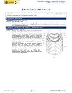
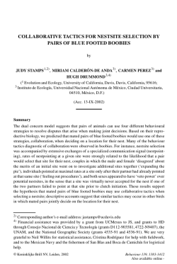
United States Patent
[19]
Miller et al.
[54]
ACHROMATIC FIBER OPTIC COUPLER
_
[75]
Inventorsr
Wilham J- M11191‘; Carlton M-
5,011,251
[45]
Date of Patent:
Apr. 30, 1991
4,931,076
6/1990
4,948,217
8/1990 Keck et a1. ..................... .. 350/96.l5
_
Donald R. Young, Jr., all of Coming,
N.Y.
Berkey ................... .. 350/9615 X
_
Prlma'lv Examiner-John D- Lee
Assistant Examiner—-Phan T. Heartney
Attorne , A em, or Firm-William J. Simmons, Jr.
[73] Assignee: Corning Incorporated, Corning, NY.
[21] Appl. No.: 447,808
y g
[57]
’
[22] Filed‘
Patent Number:
4,877,300 10/1989 Newhouse et al. ........ .. 350/9633 X
.
Truesdale; David L. Weidman;
.
[11]
ABSTRACT
An achromatic ?ber optic coupler of the type wherein
Dec’ 8’ 1989
?rst and second single-mode optical ?bers, each having
[51]
Int. Cl.5 .............................................. .. G02B 6/26
a core and a cladding, are fused together along a portion
[52]
US. Cl. ............................ .. 350/9615; 350/96.l0;
.
350/95-20
Fleld of Search ............. ..
96.10,
1,
of the lengths thereof to form a coupling region. A
matrix glass of lower index than the ?ber claddings
Surrounds the coupling region. The ?ber diameters are
350/96-12’ 9620
smaller in the coupling region than in the remainder of
the ?bers. The refractive index n; of the cladding of the
?rst ?ber is different from the refractive index n;’ of the
cladding of the second ?ber, the difference between the
[56]
References Cited
Us’ PATENT DOCUMENTS
4,474,431 10/1984 Bl‘iCh?llO ........................ .. 350/9615
refractive indices H2 and 112' being Such that the coupler
11302126 ft 1211'
,
,
o
r
e
a.
4,786,130 11/1988 Georgiou et al.
4,798,436 1/1989 Mortimore
exhibits very little change in coupling ratio with wave~
.
350/96.l5
350/96.l5
length We‘ a band °f wavelengths'
4,822,126 4/1989 Sweeney et a1. ............... .. BSD/96.15
26 Claims, 5 Drawing Sheets
_
@_.,-
US. Patent
Apr. 30, 1991
Z2QOwFJ<m-ED>U ".25xE30L:m
0
O 0.
O.
O
Sheet 1 of 5
5,011,251
02l.I 0 000.5O
m
.
F.m..
1O
O 0. 5 0
4
J0.ADC 04.10%5)
. 0.
0 m O
40.
US. Patent
Apr. 30, 1991
Sheet 2 of 5
5,011,251
.56 -
.54 -
'
.52 '
e
.50 -
CPOUWLEDR
I’
\\
,
,
\\
.48
\\
\
/
.46 -
.44 .42 I4,0
J_
I250
1
a
I
I350
I450
WAVELENGTH (nm)
l
I550
Fig. 5
PARAMETER. Aclods- 0.005
0! O
C%OUPLED POWER
VELOCITY(cm/se)
O
O
0 012
0.75
STRETCH (cm)
Fig. 7
REFACTIV
INDEX
RADIUS
Fig. .9
‘I
US. Patent
Apr. 30, 1991
Sheet 3 of 5
5,011,251
.03 -
4@wm<ouvz_
.2
.3
INCREMENTAL INCREASE IN CL (W190)
nls
US. Patent
Apr. 30, 1991
dwn_.QOMNEQ
l
a
l
|
In
l
L
.OnN
QNKOIDQ'I’ON-Q“
(SP) 830'! NOLLHBSNI
I
p
N
I6POZEmJw>5<3 stQ
Sheet 5 of 5
5,011,251
1
5,011,251
2
tered around about 1310 nm and 1530 nm. These win
dows need not have the same width; their widths could
be 80 nm and 60 nm, for example. An optimally per
ACHROMATIC FIBER OPTIC COUPLER
forming achromatic coupler would be capable of exhib
CROSS-REFERENCE TO RELATED
iting low values of coupled power slope over essentially
APPLICATION
the entire single-mode operating region. For silica
This application is related to US. patent application
based
optical ?bers this operating region might be speci
Ser. No. 447,796 (G.E. Berkey 20) entitled “Chlorine
?ed as being between 1260 nm to 1580 nm, for example.
Doped Optical Component” ?led on even date here
It is noted that the total permissible variation in power
with.
10 includes insertion loss and that the permissible power
BACKGROUND OF THE INVENTION
variation speci?cation becomes tighter as insertion loss
increases. Furthermore, for a 3 dB coupler, for example,
This invention relates to single-mode ?ber optic cou
the coupled power at the center of the window should
plers that are capable of effecting a relatively uniform
be 50%. If the 50% coupling wavelength is not at the
coupling of light from one ?ber to another over a rela
15 center of the window, the coupled power speci?cation
tively broad band of wavelengths.
becomes even tighter.
Coupling occurs between two closely spaced cores in
a multiple core device. Fiber optic couplers referred to
herein as “fused ?ber couplers” have been formed by
positioning a plurality of ?bers in a side-by-side relation
ship along a suitable length thereof and fusing the clad
dings together to secure the ?bers and reduce the spac
ings between the cores. The coupling ef?ciency in
creases with decreasing core separation and, in the case
of single-mode cores, with decreasing core diameter.
In the following discussion, the relative refractive
index difference AM between two materials with refrac
tive indices n,, and n1, is de?ned as
Aa-b=(nn2—nb2)/2na2
(1)
For simplicity of expression, A is often expressed in per
cent, i.e. one hundred times A.
European published patent application No. 0302745
A usual requirement for ?ber optic couplers is that
teaches that various coupler properties can be improved
by inserting the ?bers into a capillary tube prior to
the ?bers extending therefrom, referred to herein as
heating and stretching the ?bers, thereby resulting in
with standard system ?bers to which they will be con
nected in order to minimize connection loss. For exam
ple, the outside diameter and the mode ?eld diameter of
the coupler pigtails should be substantially the same as
those of a standard ?ber. One of the ?bers employed in
the fabrication of the coupler can be a standard, com
“pigtails”, be optically and mechanically compatible
the formation of an “overclad coupler”. After the ?bers
have been inserted into the tube, the tube midregion is
heated to cause it to collapse onto the ?bers; the central
portion of the midregion is thereafter drawn down to
that diameter which is necessary to obtain the desired
coupling. The coupling region of an overclad coupler is
hermetically sealed, and the optical characteristics
thereof are relatively insensitive to changes in tempera
ture. The tube also greatly enhances the mechanical
strength of the coupler.
35
mercially available ?ber. That feature of the other ?ber
that is modi?ed to change the propagation constant
should affect the outside diameter and mode ?eld diam
eter of the pigtail portion of the other ?ber as little as
possible.
Identical optical ?bers are used to make overclad
US. Pat. No. 4,798,436 (Mortimore) discloses a 3 dB
couplers referred to herein as “standard couplers”, the 40 fused ?ber coupler wherein different propagation con
coupling ratio of which is very wavelength dependent.
stants are obtained by pretapering one of the ?bers.
A standard coupler which exhibits 3 dB coupling at
First and second identical standard ?bers can be used to
1310 nm cannot function as a 3 dB coupler at 1550 nm
form such a coupler. The central portion of the ?rst
because of that wavelength dependence. A 3 dB cou
?ber
is initially heated and stretched such that the core
pler is one that couples 50% of the power from a ?rst 45 and the cladding diameter thereof in the tapered region
?ber to a second ?ber. A standard coupler can be char
is smaller than the core and cladding diameter of the
acterized in terms of its power transfer characteristics in
a window centered about 1310 nm, which is referred to
second ?ber. The pigtail portions of the stretched ?ber
can be connected with low loss to a standard system
as the ?rst window. For example, a standard coupler
might exhibit a coupling ratio that does not vary more 50 ?ber since the ends thereof are identical to the ends of
the stretched ?ber. However, since a separate pre
than about :t5% within a 60 nm window.
stretching operation is employed for each coupler
It has been known that an achromatic coupler, the
made, and since ?ber diameter varies continuously
along
the length thereof‘, it is difficult to maintain pro
than it is for a standard coupler, can be formed by em
ploying ?bers having different propagation constants, 55 cess reproducibility. Also, a pretapered ?ber is fragile
and dif?cult to handle.
i.e. by using ?bers of different diameter and/or ?bers of
_U.S. Pat. No. 4,822,126 (Sweeney et al.) teaches a 3
different refractive index pro?le or by tapering one of
dB fused ?ber coupler wherein Acom, the relative re
two identical ?bers more than the other. There is no
fractive index difference between the two coupler
widely accepted de?nition of achromatic couplers. The
least stringent de?nition would merely require an ach 60 cores, is 0.061%. The value of Ame; is obtained by sub
stituting the two core refractive indices of the Sweeney
romatic coupler to exhibit better power transfer charac
et al. patent into equation (1) and solving for A. It is
teristics than the standard coupler in the ?rst window.
apparent from FIG. 6 of the Sweeny et al. patent that
More realistically, the speci?cation is tightened by re
the value of Acm, should have been greater than 0.061%
quiring an achromatic coupler to perform much better
than the standard coupler in that ?rst window, or to 65 in order to have achieved good achromaticity with
standard diameter ?bers. However, when AB is ob
require it to exhibit low power transfer slopes in two
tained by employing ?bers having such large differ
windows of speci?ed widths. These windows might be
ences between the core refractive indices, the mode
speci?ed, for example, as being 100 nm wide and cen
coupling ratio of which is less sensitive to wavelength
3
5,011,251
cladding of refractive index less than m, the refractive
index n; of the cladding of the ?rst ?ber being different
from the refractive index n;’ of the cladding of the
second ?ber. The difference between n; and n2’ is such
that the value of Adad, is greater than zero but less than
0.03%. The midregion of the tube is collapsed onto
?bers, and the central portion of the midregion is
stretched until a predetermined coupling occurs be
ence between the core refractive indices to provide a
Arms greater than 0.061%, Sweeney et al. maintained
that value of Awm and, in addition, etched the ?ber
claddings in order to improve achromaticity.
The Sweeny et al. patent states that although wave
length independence is achieved, as contemplated
4
the ?bers comprises a core of refractive index m and a
?eld diameter of one of the coupler pigtails differs suffi
ciently from that of a standard ?ber that it will not
ef?ciently couple to the ?bers of the system in which
the coupler is utilized. Rather than increasing the differ
- 0 tween the ?bers.
therein, by having the cores of different indices of re
The step of stretching may comprise providing rela
fraction, similar results could be achieved by keeping
tive movement between the ends of the tube, and vary
the cores at like indices of refraction and making the
ing the rate at which the relative movement occurs. The
claddings one different from the other with respect to
stretching rate can vary continuously, or the variation
indices of refraction. It will be obvious from the follow 5 can occur in descrete steps. One stretching operation
ing discussion that it is impossible to form achromatic
can stop after a predetermined coupling is achieved;
overclad-type 3 dB couplers wherein the difference
thereafter, stretching can occur at a second stretch rate.
between the refractive indices of the ?ber claddings is
The stretching operation can be stopped before a
such that Ad“, is 0.06%, assuming that the core and
predetermined coupling is achieved; thereafter, the
cladding diameters of the two ?bers are identical. The 20 central portion of the tube midregion can be reheated,
value of Adads is obtained by substituting the cladding
and the central portion of the tube midregion can again
index n;’ of one ?ber and the cladding index n; of the
be stretched. The reheat temperature is preferably
other ?ber for no and rib, respectively, of equation (1)
lower than the temperature to which the tube is initially
and solving for A.
heated. The last employed stretch rate may be lower
25
than the ?rst stretch rate.
SUMMARY OF THE INVENTION
In an embodiment wherein a ?rst ?ber extends from
It is an object of the invention to provide a single
both ends of the tube, and a second ?ber extends from
mode achromatic ?ber optic coupler that is character
ized by a very small change in coupled power over a
wide band of wavelengths. Another object is to provide
an achromatic coupler, the connection pigtails of which
can be coupled with low insertion loss to system ?bers.
Yet another object is to provide an achromatic coupler,
wherein the feature or parameter that modi?es the
only the second end of the tube, the coupler preform
can be stretched until some coupling begins to occur
between the ?bers. Detector can be connected to the
ends of the ?rst and second ?bers which extend from
the second end of the tube. The coupled power is em
ployed to maximize the power coupled from the second
propagation constant B of the non-standard ?ber has 35 ?ber to its respective detector. The ratio of the optical
power coupled to the two detectors is used to generate
negligible effect on the ?ber mode ?eld diameter. A
the signal which stops the stretch operation.
further object is to provide a reproducible method of
making achromatic overclad ?ber optic couplers.
BRIEF DESCRIPTION OF THE DRAWINGS
The achromatic coupler of the invention comprises
an elongated body of matrix glass having a refractive 40 FIG. 1 is a cross-sectional view of an overclad cou
index m. The body includes two opposed ends and a
pler.
I
midregion. A plurality of optical ?bers extends longitu
dinally through the body, each of the ?bers comprising
ing time for couplers having two different overclad
FIGS. 2 and 3 are graphs of output voltage v. stretch
refractive indices.
FIG. 4 is a graph of the coupled power slope (cen
index less than n1 but greater than n3. The refractive 45
tered around 1310 nm) plotted as a function of Adads.
index n; of the cladding of the ?rst ?ber is different from
FIG. 5 shows theoretical spectral response curves for
the refractive index ng' of the cladding of the second
single-window and double-window achromatic cou
?ber by such an amount that the value of Aclads is
plers wherein AC1“, is 0.005%.
greater than zero but less than 0.03%. The ?bers are
FIG. 6 is a graph which schematically illustrates the
fused together along with the midregion of the matrix
a core of refractive index n1 and a cladding of refractive
glass. The diameters of the optical ?bers in the central
portion of the midregion are smaller than the diameters
thereof at the ends of the body, whereby a portion of
temporal variation in percent coupled power during the
stretching of couplers having different values of Adad,
FIG. 7 is a graph illustrating non-uniform stretch
rates.
the optical power propagating in one of the ?bers cou
FIG. 8 is a graph illustrating the effect of chlorine on
55
ples to the other of the ?bers.
Adam
The value of Acladsis preferably greater than 0.005%.
_FIG. 9 is a refractive index pro?le of a non-standard
To form a coupler that is capable of coupling about
?ber employed in the coupler of the invention.
50% of the power from the ?rst ?ber to the second ?ber
FIGS. 10-12 illustrate achromatic couplers having
at a predetermined wavelength, the value of Adm is
preferably less than 0.02%. The refractive index n; is 60 more than two ports at one end thereof.
FIG. 13 is a cross-sectional view of a capillary tube
preferably such that 112.3 is greater than 0.4%. Couplers
after optical ?bers have been inserted therein.
made in accordance with the invention have exhibited
an insertion loss less than 4 dB in each leg thereof over
a 300 nm range of wavelengths up to 1565 run.
The achromatic ?ber optic coupler of the present 65
invention is formed by inserting into a glass tube at least
a portion of each of a plurality of optical ?bers so that
the portions occupy the midregion of the tube. Each of
FIGS. 14 and 15 are schematic illustrations of two
steps during the formation of an antire?ection termina
tion on a ?ber.
FIG. 16 is a schematic illustration of an apparatus for
collapsing a capillary tube and stretching the midregion
thereof.
5
5,011,251
6
FIG. 17 is a partial cross-sectional view illustrating
the collapse of the glass tube around the ?bers to form
toring the output power at one or more of the output
a solid midregion.
FIG. 18 is a partial cross-sectional illustration of a
being formed, a light source can be connected to an
?bers during the stretch operation. If a 2x2 coupler is
input end of the ?rst and second ?bers, and a detector
can be aligned with the output ends thereof, the ?bers
being manipulated to maximize the output power cou
?ber optic coupler after it has been drawn down and
sealed at its ends.
FIG. 19 is a graph illustrating the spectral insertion
loss curves for an achromatic coupler produced by the
method of Example 1.
DESCRIPTION OF THE PREFERRED
EMBODIMENTS
pled to each detector. During stretching, the input end
of only the ?rst ?ber is connected to a source, and the
output ends of both ?bers are monitored. The detection
l0 of a predetermined ratio of powers at the outputs of the
?rst and second ?bers can be used as an interrupt to
cause the computer controlled stages to stop pulling the
The drawings are not intended to indicate scale or
relative proportions of the elements shown therein.
Referring to FIG. 1, each of the optical ?bers F1 and
sample. If a 1x2 coupler is being formed, the second
?ber cannot be accurately positioned with respect to
certain detectors until some light is coupled thereto
from the ?rst ?ber. An achromatic coupler can be made
F2 has a core of refractive index n1 surrounded by clad
by monitoring only the output from the ?rst ?ber.
ding of refractive index lower than m. The claddings of
?bers F1 and F2 have different refractive indices n; and ' When the output from the ?rst ?ber drops to a predeter
mined value, the system is instructed to stop stretching.
n2’, respectively, the values of which are such that the
propagation constants of those ?bers differ to the extent 20 An alternative procedure for monitoring 1x2 couplers is
described below.
necessary to provide achromaticity.
After having determined the proper stretching dis
A coupler preform is formed by threading ?bers F1
tance to achieve predetermined coupling characteris
and F2 through glass overclad tube 0, the refractive
index n; of which is less than the refractive indices of
tics, the apparatus can be programmed to move the
extending from the tube preferably have protective
coating material (not shown in this illustrative embodi
cation of subsequent couplers that are to have said pre
determined characteristics. The timing sequences that
have been used in the fabrication of a particular type of
coupler can be entered in a separate multiple command
?le that the computer recalls at run-time. The collapse
and stretch steps that are required to make that particu
lar coupler can be executed in succession by the com
puter on each coupler preform to reproducibly manu
facture couplers. The process parameters that can be
the ?ber claddings. Whereas those portions of the ?bers 25 stages that proper stretching distance during the fabri
ment), those portions thereof within the tube have no
coating. The original diameter of the tube is d1. The
midregion of the coupler preform is evacuated and
heated to collapse it onto the ?bers. The tube is re
heated and the ends thereof are pulled in opposite direc
tions to increase the tube length and reduce its diameter.
The combined rate at which the two tube ends move
away from each other constitutes the stretch rate. The 35 controlled by the computer to ensure coupler reproduc
central portion of the stretched midregion constitutes
ibility are beating times and temperatures, gas ?ow
neckdown region N of diameter d; where the ?ber
cores are sufficiently closely spaced for a suf?ciently
long distance 2 to effect the desired coupling therebe
stretch the coupler preform.
rates, and the rate or rates at which the stages pull and
If the device that is being made is a 3 dB coupler, for
tween. Region N is illustrated as having a constant 40 example, the stretching operation is not stopped when
the output power from the two ?bers is equal. Various
diameter even though a slight taper exists therein,
parts of the system exhibit momentum, whereby
whereby the longitudinal center of section N exhibits
stretching of the coupler preform continues after the
the minimum diameter. Draw ratio R, which is equal to
stage motors are instructed to stop. The coupling ratio
d1/d1, is a critical parameter in determining the optical
characteristics of the particular device being made. A 45 therefore changes after the stopping signal is generated.
Also, the coupling characteristics may change as a
preferred range of draw ratios for achromatic overclad
newly formed coupler cools down. Experiments can be
couplers is between about 3:1 and 10:1 depending upon
performed on a particular type of coupler to determine
the value of Adm and the amount of power to be cou
that coupling ratio which must be used to generate the
pled. Tapered regions T connect the neckdown region
with the unstretched end regions of tube 0. The dura 50 interrupt signal in order to achieve a predetermined
coupling ratio after the device cools.
tion of the heating period for the stretch step is shorter
Following are examples of the various stretching
operations that can be performed.
A. Heat the coupler preform, and stretch it at a single
to control process steps in the manufacture of optical 55 rate until a predetermined coupling has been achieved.
B. After subjecting the coupler preform to a single
devices as evidenced by U.S. Pat. Nos. 4,392,712 and
heating step, stretching it at differing stretch rates until
4,726,643, 4,798,436, U.K. Patent Application No. GB
a predetermined coupling has been achieved. Two or
2,183,866 A and International Publication No. WO
more discrete stretch rates could be employed, or the
84/04822. Furthermore, computers are often employed
in feedback systems which automatically perform such 60 stretch rate could continually vary with respect to time.
This stretching technique has been employed to tune
monitor and control functions. A suitably programmed
the power transfer characteristic, i.e. the amount of
Digital PDP 11-73 microcomputer can be utilized to
power transfered from the input ?ber to the output ?ber
perform these functions. During the tube collapse and
than that for the tube collapse step; only the central
portion of the midregion is stretched.
It is conventional practice to monitor output signals
stretch steps, the ends of the tube are affixed to com
during the ?rst power transfer cycle of the coupler
puter controlled stages. The amount of stretching to 65
which the tube must be subjected to achieve given char
preform stretching operation.
acteristics is initially determined by injecting light en
ergy into the input ?ber of a coupler preform and moni
stretch which does not achieve the predetermined cou
pling; reheat the resultant device and perform a second
C. Heat the coupler preform and perform a ?rst
7
5,011,251
8
the coupled power begins to vary until it ?nally stabi
lizes at point d when it is suf?ciently cool that there is
stretch. The heat and reheat steps may be performed at
a single temperature or at different temperatures. The
?rst and second stretch steps can be done at the same
stretch rate or at different stretch rates. More than two
no further change in stress or refractive index within the
coupler. It is possible, by experimentation, to form a
coupler, the 3 dB point of which is within 10 nm of the
heat and stretch steps could be performed.
A species of stretching embodiment C is especially
useful in the formation of 1x2 couplers. The stretching
operation is temporarily terminated after some minimal
amount of power has been coupled to the second ?ber.
For example, stretching could be stopped after the cou
pler preform has been stretched some predetermined
desired wavelength by causing the stretching operation
to stop at some predetermined coupling other than
50%.
The meandering of the coupling ratio upon cooling of
the coupler can be essentially eliminated by utilizing
overclad tubes of suf?ciently high refractive index that
the value of 132.3 is greater than about 0.4%. This stabi
lizing effect is illustrated in FIG. 3 wherein reference
distance, such as between 90% and 99% of the total
distance required to achieve the ?nal coupling ratio.
letters similar to those of FIG. 2 are represented by
primed reference numerals. The amount of coupled
power begins to decrease at point a’, the computer con
The second ?ber can be connected to a detector, and
the power coupled to that detector can be maximized.
Thereafter, a second stretching operation can be initi
trolled stages stop moving at point b’, and the stretching
ated, the interrupt signal being based on the ratio of the
two output signals. The second stretching operation is
step is terminated at point e’. During cooling, the cou
preferably conducted at a ?nal stretch rate that is lower
pled power varies only slightly until it stabilizes at point
than the initial stretch rate. Also, during the second 20 d’. After the stretching has stopped (points 0 and c’), the
stretch, it is preferable to employ a ?ame which has a
coupled power will more predictably reach point d’
lower temperature and/or which is less focussed than
than point d.
the ?ame employed during the ?rst stretch.
A theoretical analysis was made of 3 dB couplers of
Tube 0 can be characterized by the symbol A23, the
the type wherein AB was obtained by ?ber cladding
value of which is obtained by substituting n; and n3 into 25 index difference. Coupled mode theory was used to
equation (1). Commercially available single-mode opti
model the behavior of the achromatic couplers [A. W.
cal ?bers usually have a value of n; that is equal to or
Snyder and J. D. Love, Optical Waveguide Theory.
near that of silica. If silica is employed as the base glass
Chapman and Hall, New York, 1983]. In accordance
for the tube, a dopant is added thereto for the purpose of
with this theory, the mode ?eld of the overclad coupler
decreasing the tube refractive index m to a value lower 30 is assumed to be a linear combination of the fundamen
than n2. In addition to lowering the refractive index of
tal modes #11 and #12 of each of the ?bers F1 and F; in the
the tube, the dopant B203 also advantageously lowers
absence of the other ?ber, i.e. with the ?ber surrounded
the softening point temperature thereof to a value lower
by overclad index n3 only. The mode ?elds and propa
than that of the ?bers. This enhances to a certain extent
gation constants can be determined exactly for such a
the collapsing of the tube onto the ?bers; the tube glass
structure [M. J. Adams, An Introduction to Optical
?ows around the ?bers without distorting their shape.
Waveguides].
For certain purposes it may be desirable to employ a
The coupling constant which describes the optical
tube glass that is suf?ciently hard that the tube slightly
coupling between the two cores can then be written as
?attens the ?bers as it forces the ?bers together. Fluo
an overlap integral:
rine can also be employed to lower the tube refractive 40
index. Suitable tube compositions are SiOz doped with l
C= f 411(r)w2(r')(n—n')dA
(2)
to 25 wt. % B103, SiOz doped with 0.1 to approxi
In this equation, #11 and iii; are the mode ?elds of the two
mately 2.5 wt. % ?uorine, and SiO; doped with combi
nations of B203 and fluorine. When A24 is below about
cores, r and r’ are the radial distances from the center of
to soften the tube glass, whereby it excessively deforms
the ?bers during the collapse step. The value of 132-3 for
standard couplers has therefore usually been between
of index ng, and the integral is over the entire cross-sec
the cores of ?bers F1 and F2, respectively, n is the index
0.2%, the amount of B203 in a silica tube is insuf?cient 45 structure of the entire coupler, n' is the index structure
with the core of F1 replaced by overcladding material
tion of the coupler (but n—n' is only non-zero over the
core and cladding of ?ber F1). The mode ?elds are
plers have been made from preforms comprising tube 50 assumed to be normalized in this equation, i.e. the inte
and ?bers exhibiting refractive index values such that
grals f tlqzdA and flllzzdA both equal 1.
152.3 is within that range. However, process reproduc
While these are tapered devices, their behavior is
ibility is enhanced by employing preforms having 152.3
adequately modeled by assuming a constant draw ratio
values above that previously employed range.
over a given coupling length., with no coupling outside
To demonstrate the effect of the overclad glass, refer 55 this length, i.e. assuming that the diameter of region N
0.26% and 0.35%. Suitable achromatic overclad cou
ence is made to FIGS. 2 and 3 which are plots of the
voltage from a detector connected to the output end of
of FIG. 1 is constant over the entire length 2. This
approximation works well since the coupling constant is
a rapidly increasing function of draw ratio, and thus the
behavior of a coupler is dominated by the behavior at
the input ?ber during the manufacture of 1x2 couplers
wherein the values of A}; are 0.36% and 0.48%, respec
tively. Referring to FIG. 2, the output is initially highest
60
at point a since coupling has not yet occurred. As the
stretching process is initiated and power begins to cou
ple, the power remaining in the input ?ber begins to
the highest draw ratio. Using this approximation, with
the power launched into core 1, then, as a function of z,
the length along the coupler axis, the power in the two
cores is given by
decrease at some point in time after point a. At point b,
the detected power is such that the computer controlled 65
stages are instructed to stop moving. A few microsec
onds later, the stretching step is terminated (point c),
and the ?nished coupler begins to cool. During cooling,
and
9
5,011,251
10 '
values of Adm have been made having draw ratios as
low as about 3.5:1. The draw ratio can be even lower
where the factor F is given by
ewe-ell"
for taps (less than 50% coupling) since less stretching is
required. As the value of Adads increases, the draw ratio
(5) 5 must increase in order to achieve the desired coupling
ratio. Although FIG. 4 would seem to suggest that a
AC1“; value of 0.025% would be desirable from the
standpoint of providing very good achromaticity, such
where B1 and B2 are the propagation constants of ?bers
a coupler is dif?cult to make since the draw ratio re
F1 and F2, respectively.
quired to make it is around 10:1. Also, for reasons dis
Optimal achromatic performance was de?ned, for a
single-window device having a center wavelength of
cussed below, the coupled power at higher values of
AC1“; may be inadequate to achieve the desired coupling
1310 nm and a width of 50 nm, as being the point where
P1(l297.5 nm)=P2(l322.5 nm)=0.5
ratio.
While a coupler preform is being stretched to form a
(6)
coupler, the diameter of neckdown region N becomes
smaller with increasing time. FIG. 6 shows that the
The achromaticity was de?ned as
13 s
Achromaticity = —--—————P2(
3 “mg-5-nix 1310 nm)
coupled power varies during the stretching process.
(1)
20
The coupled mode model was used to determine a
The curves of FIG. 6 do not bear an exact relationship
with respect to one another; rather, it is intended that
they qualitatively illustrate the relative relationship
between the temporal coupled power curves of cou
suitable range of Adads. Most of the assumptions which
plers having different Adm values. During the stretch
nanometer) calculated for that combination.
As shown in FIG. 4, the theoretical analysis revealed
that the variation in coupled power (at 1310 nm) in
example a 10% tap, might easily be made by stretching
ing of a standard coupler (Ac1ads=0), the coupled power
were made concerning coupler parameters are based on
work done on standard overclad couplers. Fiber F1 was 25 relatively quickly reaches 50% and eventually reaches
almost 100%. During the stretching of devices having
assumed to be a standard 125 um outside diameter sin
greater values of Ada,“ , greater time periods are re
gle-mode ?ber having a core radius of 4 pm. The core
quired to achieve 50% coupling, and the maximum
and cladding refractive indices n1 and n; were assumed
possible amount of coupled power decreases. For a
to be 1.46l000 and 1.455438, respectively. It was as
given set of stretching conditions including rate of
sumed that ?ber F2 was identical to ?ber F1 except that
the cladding index ng' was greater than n;. The value of
stretch, temperature of the coupler preform, and the
A24 was assumed to be 0.3%. In order to determine the
like, there will be a value of Adm for which the coupled
combination of draw ratio and length 2 for which ach
power just reaches 50% on the ?rst peak of the coupled
romaticity was best, P2 was calculated at the appropri
power curve. For a given set of draw conditions, this
ate wavelengths for a range of draw ratios. The combi
value of AC1”, is shown in FIG. 6 to be 0.015%. For
nation of draw ratio and coupling length 2 which satis
higher values of AC1“, , such as 0.025%, the ?rst power
?ed equation (6) was determined, and then the achro
transfer peak of the coupled power curve cannot pro
maticity (the variation in coupled power in percent per
vide 50% coupling. However, it can be seen that a
creases as the value of AC1“; decreases. This is in accor
dance with the expected relationship whereby coupler
achromaticity decreases as the difference between the
?ber propagation constants decreases. The relationship
shown in FIG. 4 is for couplers having a A24, value of
0.3%. For couplers having greater values of Az-3, the
curve is displaced toward higher values of variation in
percent coupled power. When the value of Adm is less
than 0.005%, the variation in percent coupled power
rapidly increases. The achromaticity therefore rapidly
decreases at values of Ada; below this value. Also, as
the value of A6104, decreases below 0.005%, the required
length of the neckdown region increases to such an
extent that the resultant achromatic coupler would be
impractical in that it would be undesirably long and
would be dif?cult to make.
device for coupling less than half the input power, for
a coupler preform having a Acl'ads value of 0.025% until
the coupled power is 10%, a value that can be attained
on the ?rst peak.
The curves of FIG. 6 are not continued in time any
further than the extent necessary to illustrate the spe
ci?c point being discussed. The ?rst power transfer
peak is shown'for couplers wherein Aclads is 0.015 and
0.025. Subsequent power transfer peaks are not shown.
However, if the coupler preforms were stretched for
longer periods of time, the coupled power would con
tinue to oscillate between zero and some maximum
value, the period of each subsequent oscillation being
narrower than the previous one. If the curves represent
ing couplers having AC1“: values of 0 and 0.005 were
continued in time, they would experience similar oscil
lations in coupled power. The relationship between
coupled power and coupling length‘ (which is a function
of stretching time) over a plurality of coupled power
peaks is graphically illustrated in the aforementioned
FIG. 5 shows the theoretical relationship of coupled
power with respect to wavelength for both single-win
dow and double-window couplers, with Ac1ad$=0.005%
and A2-3=0.3%. The value of dl/dzis 6.6 for the single 60 U.S. Pat. No. 4,798,436.
It is assumed that curve t (Ac1ads=0.025%) is for a
window device as determined by requiring equation (6)
to be satis?ed. The value of (ll/d2 is 6.2 for the double
window device as determined by requiring an analo
gous equation to be satis?ed for the wavelengths 1310
nm and 1550 nm.
stretching operation wherein the coupler preform is
heated once and stretched at a single rate. If all other
conditions remain the same, the power transfer curve
65 can be
displaced upwardly to curve t’ (toward greater
Whereas the model indicated that a draw ratio of
about 6:1 would be needed to form a coupler wherein
power transfer) by stretching the coupler preform at
Adm is 0.005%, 3 dB achromatic couplers having low
more than one stretch rate as illustrated in FIG. 7. By
11
5,011,251
12
way of example only, FIG. 7 illustrates a stretch tech
nique involving stretching at two discrete rates (curves
The process of making the non-standard ?ber is facili
tated by the low value of Adad; that is required to form
s1 and s2) and a technique wherein the stretch rate varies
an achromatic coupler. When added to silica, com
monly employed dopants such as B203, ?uorine, GeO;
continually with respect to time (curve s’). In accor
dance with a speci?c embodiment depicted in FIG. 7,
and the like have a relatively large effect on refractive
index. It is therefore dif?cult to deliver such dopants in
the small, precisely controlled amounts that are neces
sary to change the refractive index of the base glass to
an extent suf?cient to provide a Adm value between
0.005% and 0.03%. It has been found that chlorine has
a sufficient effect on the refractive index of silica that it
can be used as a dopant in the cladding of the non-stand
ard ?ber. Since the change in refractive index per
the coupler preform is heated and stretched 0.2 cm at a
stretch rate of 0.95 cm/sec, the stretch rate abruptly
decreasing to 0.45 cm/sec while the coupler preform is
stretched an additional 0.55 cm.
For certain stretching conditions, including a Adad,
value of about 0.025% or higher, a subsequent power
transfer peak such as the third peak might be required to
reach the desired coupling value, e.g. 50%. Since the
third peak is much narrower than the ?rst, the stretch
ing operation must be stopped at precisely the right time
in order to achieve the desired coupling ratio. If stretch
ing is continued for only a short additional length of
time, the neckdown ratio may change suf?ciently to
cause the coupled power to drastically decrease. It is
dif?cult to draw such a coupler when output power is
being monitored to stop the draw, and it is almost im
possible to make such a coupler by drawing to a prede
termined length. Furthermore, the achromaticity be
comes degraded when the coupler has to be stretched
beyond the ?rst power transfer peak. For the aforemen
tioned reasons, the maximum preferred value of Ad“;
for 3 dB couplers is about 0.025% and the maximum
value of Add; for a power tap is about 0.03%.
In view of the value of Atom that was required for the
achromatic fused ?ber coupler taught in the aforemen
tioned Sweeney et al. patent, the above-de?ned range of
AC1“, that is suitable for achromatic overclad couplers is
unexpectedly low. It appears that the presence of the
overclad tube enables the achievement of achromaticity
with relatively small values of Aclads and that a value of
Aclads larger than 0.03% would be required if no over
clad tube were employed, i.e. for a fused ?ber coupler.
The low range of values of Adads that was determined
by the aforementioned model has been veri?ed by ex
perimental results. When couplers were formed having
values of Adad, below about 0.005%, AB was so insignif
icant that coupling behavior approached that of a stan
dard coupler. Couplers having a AC1“, value in the
5
weight percent dopant in silica is much less for chlorine
than for conventional dopants such as B203, fluorine,
GeOz and the like, chlorine can be used to provide
precisely controlled refractive index values that are
only slightly higher than that of the silica to which the
chlorine is added. Furthermore, the use of chlorine
simpli?es the process of making the non-standard ?ber
since it is conventionally employed for drying purposes.
Sufficient amounts of chlorine can simply be added to
the cladding region of the' non-standard ?ber in con
junction with the drying/consolidation process.
The standard ?ber can be made by a conventional
process, such as that disclosed in US. Pat. No.
4,486,212, which is incorporated herein by reference.
Brie?y, that process consists of forming on a cylindrical
mandrel a porous preform comprising a core region and
a thin layer of cladding glass. The mandrel is removed,
and the resultant tubular preform is gradually inserted
into a consolidation furnace muf?e, the maximum tem
perature of which is between 1200" and 1700" C. and
preferably about l490° C. for high silica content glass.
The temperature pro?le of the muf?e is highest in the
central region as taught in US. Pat. No. 4,165,223,
which is incorporated herein by reference. Chlorine,
which is present in the minimum concentration that is
required to achieve drying, may be supplied to the pre‘
form by ?owing into the preform aperture a drying gas
consisting of helium and about 5 volume percent chlo
rine. The end of the aperture is plugged to cause the gas
to ?ow through the preform pores. A helium ?ushing
gas is simultaneously ?owed through the muf?e.
range of about 0.0l5% exhibited an insertion loss of less 45
The resultant tubular glass article is stretched in a
than 4 dB in each leg thereof over a 300 nm range of
standard draw furnace while a vacuum is applied to the
wavelengths up to 1565. nm.
aperture to form a “core rod” in which the aperture has
A number of advantages result from the unexpectedly
low values of Adads. Couplers having low Adads values
been closed. A suitable length of the rod is supported in
a lathe where particles of silica are deposited thereon.
can be connected with low loss into the system. One of 50 The resultant ?nal preform is gradually inserted into the
the ?bers can be a standard single-mode ?ber. To pro
consolidation furnace where it is consolidated while a
vide a AC1“; value of 0.015%, for example, the cladding
index of the other ?ber (or non-standard ?ber) need
differ from that of the standard ?ber by only 0.00022.
Such non-standard ?ber exhibits substantially the same
mode ?eld diameter as the standard ?ber. Since the
diameters of bothv ?bers are substantially identical, the
non-standard ?ber, as well as the standard ?ber, can be
connected to the system ?bers with low loss.
The required value of Aclads can be obtained by add
ing a dopant to the cladding of only one of the ?bers or
by adding different amounts of the same or different
mixture of 99.5 volume percent helium and 0.5 volume
percent chlorine is ?owed upwardly therethrough. The
resultant glass preform is drawn to form a step-index,
single-mode optical ?ber, the entire cladding of which
comprises silica doped with a residual amount of chlo
rine. When the cladding is consolidated in a standard
downfeed consolidation furnace, as described above,
about 0.04-0.06 wt. % chlorine is normally present in
the ?ber cladding.
The non-standard ?ber can be made by a process
which is initially identical to the process by which the
dopants to the claddings of the two ?bers. For example,
standard ?ber is made. For example, the core rod,
which consists of a solid glass rod of core glass, that is
the cladding of one ?ber could consist of silica and that
of the other could consist of silica doped with ?uorine 65 optionally surrounded by a thin layer of silica cladding
or B203 to lower the refractive index or silica doped
with chlorine, 6:30; or the like to increase the refrac
tive index.
glass, is initially formed. A porous layer of silica parti
cles is deposited on the rod, and the porous layer is
consolidated in an atmosphere containing an amount of
13
5,011,251
chlorine greater than that which would be necessary for
drying purposes. The chlorine concentration in the
consolidation furnace is controlled to provide the de
sired value of Adm. The amount of chlorine that is
incorporated into the base glass depends upon various
process conditions such as the maximum temperature
and temperature pro?le of the consolidation furnace,
the concentrations of chlorine and oxygen therein and
the rate of insertion of the preform into the furnace. The
porosity and composition of the preform would also
14
index of the cladding of ?ber S+is negative with respect
to the cladding of ?ber S, whereby the value of Adm of
?ber S+with respect to ?ber S is positive. The refrac
tive index of the cladding of ?ber S-is such that the
value of Adm of ?ber S-with respect to ?ber S is nega
tive.
In the 1x4 embodiment of FIGS. 11 and 12, the re
fractive index of the cladding glass of ?bers S+is such
that the value of Adm of ?bers S+with respect to ?ber
S is positive. FIG. 12 shows that ?bers S+are preferable
equally spaced around ?ber S.
Whereas the preferred manufacturing technique re
sults in a coupler having optical ?ber pigtails extending
affect the ?nal chlorine concentration. A graph such as
that shown in FIG. 8 can be generated for a given stan
dard ?ber. For the speci?c relationship shown in FIG.
8, the standard ?ber cladding contained about 0.05 wt.
% chlorine. Therefore, about 0.2 wt. % chlorine should
be incorporated into the cladding of the non-standard
?ber to achieve a Adm value of 0.015%. This chlorine
endface. Methods of making such a coupler are dis
concentration is determined by reading from the graph
closed in U.S. Pat. Nos. 4,773,924 and 4,799,949.
If the non-standard ?ber is made by initially forming
couplers is illustrated in FIGS. 13-18. A glass capillary
therefrom, the invention also applies to overclad cou
plers of the type wherein the ?bers extend through the
elongated matrix glass body but end ?ush with the body
Brie?y, the method comprises inserting a plurality of
of FIG. 8 the incremental increase in chlorine content
for the desired value of A51“; and adding 0.05 wt. %. If 20 optical ?ber preform rods into a glass tube, heating and
stretching the resultant preform to form a glass rod
desired, both ?bers could be of the non-standard type,
which is then severed into a plurality of units. Heat is
i.e. both could contain more chlorine than standard,
applied to the central region of each unit, and the cen
commercially available ?bers. For example, a Aclads
tral region is stretched to form a tapered region as de
value of 0.015% could also be obtained by utilizing
?bers, the claddings of which contain 0.10 wt. % and 25 scribed herein.
A method of making 1x2 achromatic 3 dB ?ber optic
0.23 wt. % chlorine.
a core rod comprising core glass surrounded by a thin
tube 10 having a 3.8 cm length, 2.8 mm outside diame
ter, and 270 um longitudinal aperture diameter was
layer of cladding glass (containing a small amount of
residual chlorine) and the outer cladding glass is doped 30 secured by chucks 32 and 33 of the apparatus of FIG.
16. Tube 10, which was formed by a ?ame hydrolysis
with a larger amount of chlorine, the refractive index
process, consisted of silica doped with about 6 wt. %
pro?le of the resultant ?ber would appear as illustrated
B203 and about 1 wt. % ?uorine. Tapered apertures 12
in FIG. 9. The radii of the various layers of a standard
and 13 were formed by ?owing the gas phase etchant
?ber might be 4 pm core radius r1, 10.5 um inner clad
NF3 through the tube while uniformly heating the end
ding radius r2 and 62.6 pm outer radius r3. Because of
of the tube.
the small area of the inner cladding layer, the refractive
Coated ?bers 17 and 18 comprised 125 um diameter
index of that layer need not be taken into consideration
single-mode optical ?bers 19 and 20 having a 250 pm
when specifying the cladding refractive index. That is,
diameter urethane acrylate coatings 21 and 22, respec
the effective refractive index of the entire cladding
beyond radius r1 is essentially the same as that of the 40 tively. Both ?bers had a 8 pm diameter core of silica
doped with 8.5 wt. % G602. The cutoff wavelengths of
layer between r2 and r3.
the ?bers are below the operating wavelength of the
It is noted that attempts have been made by certain
coupler. If, for example, the minimum operating wave
?ber manufacturers to reduce the amount of chlorine in
length is 1260 nm, the cutoff wavelengths of the ?bers
optical ?bers in order to lower the attenuation (see
Japanese Kokai No.63/285137). If one ?ber had a pure 45 are selected to be between 1200 nm and 1250 am. All
silica cladding (by removing the chlorine therefrom)
about 0.13 wt. % chlorine would be needed in the other
?ber to achieve a Adm value of 0.015%. However, it
has been found that the presence of chlorine in the short
lengths of coupler ?bers has little or no effect on cou 50
chlorine concentrations were measured by microprobe
techniques. The initial steps of the processes of making
both ?bers was the same; these steps are set forth above
in conjunction with a discussion of U.S. Pat. No.
4,486,212. A ?rst layer of glass particles comprising
pler loss. The additional step of removing chlorine from
SiOz doped with 8.5 wt. % GeOz was deposited on a
coupler ?bers would therefore be an unnecessary ex
mandrel, and a thin layer of S102 particles was depos
pense.
Whereas 2x2 couplers are illustrated in FIG. 1, this
ited on the ?rst layer. The mandrel was removed, and
the speci?c embodiment. More than 2 ?bers can be
joined at their waists to form an NxN coupler. Some
per minute) chlorine and 650 sccm helium ?owed into
the center hole where the mandrel had been removed.
the resultant porous preform was gradually inserted
invention also applies to other con?gurations. An NxN 55 into a furnace having an alumina muf?e where it was
dried and consolidated. During this process, an gas
coupler (N > 1) can be formed for the purpose of cou
mixture containing 65 sccm (standard cubic centimeter
pling one ?ber to N ?bers. A 1x2 coupler is described in
times, one or more ?bers are severed from one end of an
NxN coupler so that a plurality of ?bers, unequal in
number, extend from opposite ends of the coupler. The
A ?ushing gas containing 40 slpm (liter per minute)
helium and 0.5 slpm oxygen ?owed upwardly from the
embodiments of FIGS. 10-12 are schematic illustrations
bottom of the muf?e. The aperture was evacuated, and
the lower end of the tubular body was heated to 1900°
of coupled ?bers, the overclad tubing glass having been
C. and drawn at a rate of about 15 cm/min to form a 5
omitted for simplicity. The presence of an overclad 65 mm solid glass rod. The rod was severed to form sec
tions, each of which was supported in a lathe where it
glass is indicated by the symbol n3 adjacent the ?bers. In
functioned as a mandrel upon which SiOz cladding soot
the 1x3 coupler of FIG. 10, standard ?ber S is coupled
was deposited to form a ?nal porous preform.
to two non-standard ?bers S+and S-. The refractive
15
5,011,251
a. Forming a Standard Fiber
16
coated portion of coated ?ber 17 preferably being cen
tered within aperture 11. End 25 of ?ber 18 was located
between midregion 27 and end 14 of tube 10. The ?bers
were threaded through the vacuum attachments 41 and
taining 40 slpm helium, 0.5 slpm chlorine and 0.5v slpm 5 4140 , which were then attached to the ends of preform
31. Referring to FIG. 13, vacuum attachment 41 was
Oxygen ?owed through the muffle. The porous preform
slid over the end of tube 10, and collar 39 was tightened,
was consolidated to form a draw blank, the outer clad
thereby compressing O-ring 38 against the tube. Vac
ding of which had the same composition as the inner
One ?nal porous preform was gradually inserted into
the alumina muffle of a consolidation furnace having a
maximum temperature of 1490. C. A gas mixture con
cladding layer, i.e. SiOz doped with about 0.05 wt. %
uum line 42 was connected to tube 40. One end of a
chlorine. The tip of the draw blank was heated to about
2100° C., and a standard optical ?ber was drawn there
length of thin rubber tubing 43 was attached to that end
of vacuum attachment 41 opposite preform 31; the re
from, the ?ber being coated during drawing. The ?ber
maining end of the tubing extending between clamp
had an 8 pm diameter core and a 125 um diameter
jaws 44. Upper vacuum attachment 41' was similarly
homogeneous cladding layer of silica containing about
associated with line 42', tubing 43’ and clamp jaws 44'.
0.05 wt. % chlorine as a residual from the drying pro 15 The coated portions of the ?bers extended from tubing
43 and 43'.
cess.
Vacuum was applied to the lower portion of coupler
b. Forming a Non-Standard Fiber
Another ?nal porous preform was gradually inserted
preform 31 by clamping jaws 44 on tubing 43 while the
into a consolidation furnace having a sileca muffle. The
upper vacuum attachment was connected to a source of
maximum temperature of 1450“ C. The porous preform 20 nitrogen to purge the aperture contents. Jaws 44' were
then clamped against tubing 43' to apply vacuum to the
upper portion of preform 31.
taining about 2 slpm helium and 0.6 slpm chlorine. The
was subjected to an upwardly ?owing gas mixture con
porous preform was consolidated to form a draw blank,
The upper end of ?ber 17 was connected to a mono
chromater coupled to a white light source. The mono
with about 0.2 wt. % chlorine. The resultant non-stand 25 chromater was adjusted so that the ?ber was provided
with a beam 1310 nm light. The lower end of ?ber 17
ard ?ber was similar to the standard ?ber except that it
was connected to a detector which formed a part of the
had a 10.5 pm diameter inner cladding region contain
system that controls the movement of chucks 32 and 33.
ing about 0.05 wt. % chlorine and an outer, 125 um
With a vacuum of 10 inches (25.4 cm) of mercury
diameter cladding region containing about 0.2 wt. %
connected to the tube aperture, ring burner 34 was
chlorine. The refractive indices of the claddings of this
ignited. The apparatus located above ring burner 34 was
?ber and the standard ?ber were such that the value of
protected by heat shield 35. Flames of about 1800° C.
Aclads was 0.015.
were generated by supplying gas and oxygen to the
The standard and non-standard ?bers were interchan
the outer cladding of which consisted of SiOz doped
burner at rates of 0.8 slpm and 0.85 slpm, respectively.
A 6 cm long section of coating was removed from the 35 The ?ame from ring burner 34 heated tube 10 for about
25 seconds. The matrix glass collapsed onto ?bers 19
end of a 1.5 meter length of coated ?ber 18. A ?ame was
and 20 as shown in FIG. 17. Midregion 27, the central
directed at the center of the stripped region of ?ber, and
gable in the following-process.
the end of the ?ber was pulled and severed to form a
portion of which forms the coupling region of the resul
tant coupler, became a solid region wherein substan
tapered end was connected to a re?ectance monitoring 40 tially the entire lengths of ?bers 19 and 20 were in mu
tual contact.
apparatus. The tapered end was moved slowly along its
After the tube cooled, the ?ow rates of both the gas
longitudinal axis to the right (as shown in FIGS. 14 and
and oxygen were increased to 0.9 slpm, and the burner
15 wherein only the bright, central portion 23 of the
was reignited. Flames having a temperature of about
?ame is illustrated). As the tip of ?ber 20 was heated by
1900“ C. heated the center of the collapsed region to the
?ame 23 of burner 24', the glass receded and formed
softening point of the materials thereof. After 12 sec
rounded endface 25 (FIG. 15), the diameter of which
onds, the supply of oxygen to burner 34 was turned off.
was preferably equal to or slightly smaller than the
Stages 45 and 46 were pulled in opposite directions at a
original uncoated ?ber diameter. A current speci?ca
combined rate of 2.5 cm/sec until the central portion of
tion for the re?ected power is —50 dB. The resultant
tapered end (FIG. 14). The ?ber end remote from the
length of uncoated ?ber was about 2.9 cm.
50 midregion 27 was stretched 1.46 cm. The ?ame became
Tube 10 was inserted through ring burner 34 (FIG.
extinguished after the stretching operation. This in
16) and was clamped to draw chucks 32 and 33. The
crease in length was just short of the length to which
coupler preform 31 would have had to be stretched in
order to have achieved achromaticity in a single
chucks were mounted on motor controlled stages 45
and 46 which were controlled by a computer. Approxi
mately 3.2 cm of coating was stripped from the central 55 stretching operation. A sufficient amount of power
began to couple to ?ber 18 to enable the end of that
region of a 3 meter length of ?ber 17. The uncoated
sections of ?bers 17 and 18 were wiped, and a small
amount of ethyl alcohol was squirted into the tube to
temporarily lubricate the ?bers during the insertion
?ber to be connected to a detector, and the power out
put to the detector was peaked.
Flow rates of gas and oxygen to burner 34 were then
60 adjusted to 0.65 slpm and 0.6 slpm, respectively, to
process.
produce a broader ?ame having a temperature of about
Coated ?ber 17 was inserted through aperture 11
1650" C. Twelve seconds after the flame was ignited,
until its uncoated portion was situated below tube end
the oxygen flow was turned off, and stages 45 and 46
15. The uncoated portion of coated ?ber 18 was held
pulled in opposite directions at a combined rate of 0.5
adjacent the uncoated portion of coated ?ber 17, and
both were moved together toward tube end 14 until the 65 cm/sec to further increase the length of coupler pre
coating end regions become wedged in tapered aperture
form 31 by about 0.02 cm. During this step, the light
13. The uncoated portion of coated ?ber 17 was then
disposed intermediate end surfaces 14 and 15, the un
emanating from ?bers 17 and 18 was monitored at 1310
nm. The stretching operation automatically stopped
17
5,011,251
18
6. A coupler in accordance with claim 2 wherein A14
is greater than 0.4%, wherein A24 is equal to
when the ratio of the optical power from ?ber 17 to that
of ?ber 18 was 1.2, at which time the control system
instructs the stages to stop moving. Because of system
momentum, a suf?cient amount of stretching continues
to occur to provide a power ratio of 1, whereby equal
light power emanated from ?bers 17 and 18 at 1310 nm.
(n32—n22)/2n32.
_
7. A coupler in accordance with claim 1 wherein the
difference between said refractive indices ng and n2’ is
such that the insertion loss is less than 4 dB in each leg
The diameter of the midregion is reduced by the
stretching operations as illustrated by region 51 of FIG.
thereof over a 300 nm wavelength range.
8. A coupler in accordance with claim 1 wherein the
value of A01“, is greater than 0.005%.
9. A coupler in accordance with claim 8 wherein 112-3
is greater than 0.4%, wherein A24 is equal to
18.
After the coupler had cooled, the vacuum lines were
removed from the resultant coupler, and a drops 48 and
49 of heat curable adhesive were applied from a syringe
(n32-n22)/2n32.
to ends 14 and 15, respectively, of the capillary tube.
10. A coupler in accordance with claim 1 wherein
After the adhesive was cured by exposure to heat
said coupler is capable of coupling about 50% of the
(arrow H), the coupler was removed from the draw.
The resultant devices couple approximately 50% of
the signal propagating in that end of optical ?ber 17 at
power from one of said ?bers to the other of said ?bers
at a predetermined wavelength, and the value of Adam
- is between 0.005% and 0.02%.
end 14 to optical ?ber 18 at about 1310 nm and 1490 nm;
11. A coupler in accordance with claim 10 wherein
the power slope at 1310 nm is 0.077% per nm or 0.006
20 A24 is greater than 0.4%, wherein A24, is equal to
dB per nm. These couplers exhibited a median excess
(n32—n22)/2n32.
device loss of about 0.3 dB. The lowest measured excess
12. A coupler in accordance with claim 1 wherein
loss was 0.05 dB.
A24 is between 0.4% and 0.65%, wherein A24, is equal
to (n32——n22)/2n32.
13. An achromatic ?ber optic coupler comprising
?rst and second single-mode glass optical ?bers, each
The spectral insertion loss curves for a speci?c cou
pler made in accordance with the speci?c example are
shown in FIG. 19. Curve P2 represents the coupled
power. The excess loss for that coupler was 0.09 dB and
0.05 dB at 1310 nm and 1550 nm, respectively. The
insertion loss was less than 4 dB in each leg of that
coupler over a 300 nm range of wavelengths up to about
and m’ of said ?bers being lower than the refractive
index n; of said cores, said ?bers being fused together
along a portion of the lengths thereof to form a coupling
1565 nm.
region, said coupling region being surrounded by ma
having a core and a cladding, the refractive indices n2
What is claimed is:
trix glass having a refractive index n; that is lower than
the refractive indices of said claddings, the diameters of
1. An achromatic ?ber optic coupler comprising
an elongated body of matrix glass having a refractive
said ?bers being smaller in said coupling region than in
index n3, said body having two opposed ends and a
the remainder of said ?bers, and said cores being more
closely spaced in said coupling region than in the re
mainder of said ?bers, thereby forming a coupling re
gion wherein a portion of a signal propagating in one of
said ?bers is coupled to the other of said ?bers, the
difference between said refractive indices n; and n2’
midregion,
a plurality of optical ?bers extending longitudinally
through said body, each of said ?bers comprising a
core of refractive index m and a cladding of refrac
tive index less than n1 but greater than n;, the re
fractive index n; of the cladding of a ?rst of said
being such that the insertion loss is less than,4 dB in
each leg thereof over a 300 nm wavelength range.
14. A coupler in accordance with claim 13 wherein
the difference between said refractive indices ng and n2’
is such that the insertion loss is less than 4 dB in each leg
?bers being different from the refractive index m’
of the cladding of a second of said ?bers by such an
amount that the value of Aclads is greater than zero
but less than 0.03%, wherein Add, equals
(I122- ”2'2)/2I122,
thereof between 1265 nm and 1565 nm.
said ?bers being fused together along with the midre
15. A coupler in accordance with claim 13 wherein
gion of said matrix glass, the diameter of the central
A2.3
is greater than 0.4%, wherein A24 is equal to
portion of said midregion and the diameters of said
optical ?bers in said central portion being smaller 50 (113,2 —- n22)/2:132.
16. A method of making an achromatic ?ber optic
than the diameters thereof at the ends of said body,
coupler comprising the steps of
whereby a portion of an optical power propagating
in one of said ?bers couples to the other of said
?bers.
2. A coupler in accordance with claim 1 wherein the 55
difference between said refractive indices n; and n2’ is
such that the insertion loss is less than 4 dB in each leg
thereof over a 300 nm wavelength range
so that said portions occupy the midregion of said
tube, each of said ?bers comprising a core of re
fractive index m and a cladding of refractive index
less than n1 but greater than n3, the refractive index
n2 of the cladding of a ?rst of said ?bers being
different from the refractive index n2’ of the clad
ding of a second of said ?bers, the difference be
tween n; and n2’ being such that the value of A014,},
is greater than zero but less than 0.03%, wherein
3. A coupler in accordance with claim 2 wherein the
value of Adad; is greater than 0.005%.
4. A coupler in accordance with claim 2 wherein said
coupler is capable of coupling about 50% of the power
from one of said ?bers to the other of said ?bers at a
Adm equals
predetermined wavelength, and the value of A6144, is
between 0.005% and 0.02%.
inserting into a glass tube of refractive index n3 at
least a portion of each of a plurality of optical ?bers
65
5. A coupler in accordance with claim 4 wherein 152.3
is greater than 0.4%, wherein A24 is equal to
(n32—nz2)/2n32.
collapsing the midregion of said tube onto ?bers, and
19
5,011,251
20
23. A method in accordance with claim 16 wherein
stretching the central portion of said midregion until
the step of stretching comprises heating the central
a predetermined coupling occurs between said
?bers.
17. A method in accordance with claim 16 wherein
portion of said tube midregion to a ?rst temperature,
stretching the central portion of said tube midregion,
stopping said stretching operation before said predeter
mined coupling is achieved, heating the central portion
the step of stretching comprises providing relative
movement between the ends of said tube, and varying
of said tube midregion to a second temperature lower
the rate at which said relative movement occurs.
than said ?rst temperature and stretching the central
18. A method in accordance with claim 17 wherein
portion of said tube midregion.
the step of stretching comprises continuously varying
24. A method in accordance with claim 16 wherein
the rate at which said relative movement occurs.
the step of stretching comprises heating the central
19. A method in accordance with claim 17 wherein
portion of said tube midregion to a ?rst temperature,
stretching the central portion of said tube midregion at
a ?rst stretch rate, stopping said stretching operation
the step of stretching comprises stretching at one
stretch rate for a ?rst period of time and stretching at
another stretch rate for a second period of time.
20. A method in accordance with claim 16 wherein
before said predetermined coupling is achieved, heating
the central portion of said tube midregion to a second
temperature lower than said ?rst temperature and
stretching the central portion of said tube midregion at
the step of stretching comprises pulling the ends of said
tube away from each other at a ?rst stretch rate, and
a second stretch rate lower than said ?rst stretch rate.
25. A method in accordance with claim 16 wherein
the ends of said tube away from each other at a second 20
the
step of stretching comprises stretching the central
stretch rate that is different from said ?rst stretch rate.
portion
of said tube midregion at a ?rst stretch rate until
21. A method in accordance with claim 16 wherein
some coupling between said ?bers begins to occur, and
before said predetermined coupling is achieved, pulling
the step of stretching comprises pulling the ends of said
tube away from each other at a ?rst stretch rate, and
before said predetermined coupling is achieved, pulling
before said predetermined coupling is achieved, stretch
25 ing the central portion of said tube midregion at a sec
ond stretch rate different from said ?rst stretch rate.
26. A method in accordance with claim 16 wherein
said tube has ?rst and second ends, at least a ?rst of said
?bers extends from both ends of said tube, and at least a
second of said ?bers extends from only the second end
of said tube, and wherein the step of stretching com
the ends of said tube away from each other at a second
stretch rate that is less than said first stretch rate.
22. A method in accordance with claim 16 wherein
the step of stretching comprises heating the central
portion of said tube midregion, stretching the central
portion of said tube midregion, stopping said stretching
operation before said predetermined coupling is
achieved, reheating the central portion of said tube
prises stretching the central portion of said tube midre
gion until some coupling between said ?bers begins to
occur, and using the ratio of the optical power from said
midregion and further stretching the central portion of 35 ?bers to stop said stretching operation.
#
i
i
t
it
said tube midregion.
45
55
65


© Copyright 2026