
Models: Ti2 2000.1
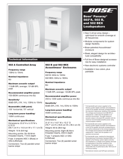
Amplifier Manual Manual del Amplificador Manuel del’amplificateur Models: Ti2 2000.1 Features: • High Efficiency Class D Topology • Compact Size for Easy Installation • Balanced Differential Input Circuitry • Audiophile NJM2068M Operational Amplifiers • Ultra High Speed IR Class D Chipset • 48dB Subsonic and 24dB Low Pass Crossovers • Robust Unregulated Power Supply • Surface Mount Component Technology • Direct Insert Power and Speaker Terminals • Audio Precision Quality Control Verification • High Temperature Plexiglass cover • RBCF- Remote subwoofer level control included • RMD - Remote Monitoring Display Port • Signal Clipping Indicators Características: • Alta eficiencia de clase D Topología • Tamaño compacto para una fácil instalación • Diferencial balanceada circuitos de entrada • Audiophile NJM2068M amplificadores operacionales • IR Chipset Ultra Alta Velocidad • 48dB Subsonic and 24dB Low Pass Crossovers • Robusta y no regulada Fuente de Poder • Tecnología “Surface Mount Component” • Conexiones directas de terminales de poder y de parlantes • Control de verificación de calidad de precisión de audio • Cubierta de Plexiglás resistente a altas temperaturas • RBCF -Control de nivel de Subwoofer remoto incluido • RMD - Puerto de display para monitoreo remoto • Indicadores de señal máxima Caractéristiques: • Topologie de classe D de gamme complète • Petit format pour faciliter l’installation • Circuit équilibré Entrée différentielle • Audiophile NJM2068M Amplificateurs opérationnels • Haute Vitesse IR de classe D chipset • Filtres croisés passe-haut et passe-bas • Alimentation électrique robuste non réglementée • Technologie de composant monté en surface • Terminaux d’alimentation et de haut-parleurs à insertion directe • Vérification du contrôle de la qualité de la précision audio • Couvercle de plexiglas résistant aux températures élevées • RBCF- Niveau de contrôle de passe-bas inclus • RMD - Entrée De L’affichage de Tension a Distance • Indicateurs de saturation du signal Phoenix Gold • www.phoenixgold.com Amplifier Owner’s Manual SPECIFICATIONS Ti2 2000.1 SPECIFICATIONS Frequency Response: Signal to Noise Ratio: Low Pass Crossover: Subsonic Filter: Low Pass Crossover Range: Subsonic Crossover Range: Bass Boost @ 45Hz: Low Level Input Range: Lowest Recommend Load: Typical Efficiency: Damping Factor: Variable Phase Adjustment: ± 1dB from 20Hz to 200Hz >90dB 24dB per Octave 48dB per Octave 30Hz to 200Hz 10Hz to 55Hz 0 to +18dB 200 millivolts to 8 volts 1 ohm 80% Greater than 200 0 to 180 Degrees RMS Power Output 1300w x 1 @ 2 ohms 2000w x 1 @ 1 ohm Power/Ground Wire Size: Recommend Power Wire Fuse: Dimensions (Includes Feet): 1/0 Gauge 150a 18.0” L x 7.1” W x 2.0” H 456mm L x 180mm W x 52mm H IMPORTANT: A power birth certificate is included for each amplifier. Ti2 amplifiers are conservatively rated and will exceed their RMS power rating shown here. All RMS power ratings and measurements are at 14.4 volts with no more than 1% THD. Phoenix Gold • www.phoenixgold.com Amplifier Owner’s Manual Crossover Settings All crossover frequency potentiometers have 41 detents or “clicks” so the end user can set the exact cross over frequency desired. clicks SUBSONIC (10~55Hz) LOWPASS (30~200Hz) 1 61 207 2 60 205 3 58 203 4 57 199 5 54 197 6 53 193 7 50 192 8 50 188 9 48 184 10 47 182 11 46 177 12 45 169 13 43 160 14 43 155 15 41 150 16 39 145 17 38 140 18 36 134 19 36 130 20 35 126 21 34 122 22 32 120 23 31 117 24 29 105 25 27 95 26 25 81 27 24 73 28 22 68 29 21 61 30 20 57 31 19 55 32 19 49 33 18 46 34 18 44 35 17 42 36 16 40 37 15 39 38 14 38 39 14 38 40 13 37 41 12 36 Phoenix Gold • www.phoenixgold.com Amplifier Owner’s Manual Ti2 2000.1 Monoblock Power Amplifier INPUT SENS Connect preamp signal cables from the head unit to these terminals. Used to reach maximum amplifier power with a wide variety of headunits. CROSSOVER FREQUENCY SUBSONIC CROSSOVER FREQUENCY Controls the lowpass crossover point for the speaker outputs. Controls the highpass crossover point for the speaker outputs to eliminate extreme low frequencies. BASS BOOST REMOTE MONITORING DISPLAY (RMD) Variable bass boost from 0 to +18dB @ 45Hz. REMOTE BASS LEVEL CONTROL (RBCF) This port is for connecting the remote subwoofer level control. This allows up to 20dB of volume adjustment. This is not a bass boost, it controls the level of the low pass signal. NOTE: This control is not compatible with the Phoenix Gold LPL44 level control. Connect optional RMD Voltage Display to this port. PHASE This allows the phase of the output to be adjusted from 0 to 180 degrees. This adjustment can help achieve better “up front” subwoofer bass and resolve subwoofer cancellation problems in certain installations. Each installation is different, slowly adjust and listen for best results. +12V SPEAKER OUTPUTS REMOTE CLIP INDICATORS (located on top of the amplifier) This must be connected to the fused positive terminal (+12V) of the car’s battery. The fuse must be located within 18 inches of the battery. This must be connected to switched +12V, usually a trigger wire coming from the head unit or ignition. GROUND This must be connected to the negative terminal of the car’s battery or bolted to a clean, unpainted part of the chassis of the vehicle. Phoenix Gold • www.phoenixgold.com Used to connect the amplifier to speakers. Ti2 2000.1’s minimum impedance is 1 ohm. Lights when the amplifier reaches near maximum output. Under heavy use the clip indicators should be flashing during the peaks of the music. The clip indicator should not stay lit for long periods of time (more than 1 or 2 seconds), if this is the case you need to reduce system volume or level of the amplifier. Amplifier Owner’s Manual System tuning 1. Install all system fuses. 2.Set the amplifier’s input sensitivity controls to their minimum positions (full counterclockwise). 3.Set all amplifier crossover switches according to your system’s design. 4.Make preliminary adjustments to the crossover frequency, usually 80Hz is good starting point for low pass and 30Hz for subsonic. It may be necessary to fine tune the crossover frequency later for the best overall sound quality. 5.If using a Remote Subwoofer Level Control, set it to maximum (full clockwise). 6.Turn the headunit on with the volume set to minimum. 7. Visually check the amplifier’s has turned on by the power LED. 8.Check the condition of all other components to make sure they are powered up. 9.Set the headunit’s tone controls, balance, and fader to the center (flat) position. Turn off any loudness or other signal processing features. 10.Set the volume control of the headunit to 3/4 of maximum volume. Play music you typically listen to through the system. 11.Turn up the sensitivity or input level control on the amplifier until the speakers reach maximum undistorted output. The clip LEDs should flash with the peaks of the music at this level. 12.Repeat sensitivity level adjustments for all other amplifiers. 13.Reduce the headunit’s volume to a comfortable level. 14.Listen to various musical selections to check overall system balance. Compare front to rear, midbass to midrange, etc. If one speaker set is too loud compared to another, then its level must be lowered to blend correctly with the other speakers. Note: For subwoofers controlled by the Remote level control, keep the level setting from step 11 or 12. Use the control to blend subwoofers with the rest of the system. The correct subwoofer volume will change depending on road noise and differences in recordings. 15.Fine tune crossover frequencies to achieve the smoothest possible blending of each speaker set. 16.Adjust the Bass Equalization Controls on the amplifier, headunit or processor upstream if necessary to increase output. Note: Use these controls sparingly. Every 3dB of boost requires double the power at 45Hz. If your subwoofer system requires a lot of boost to sound good, there may be a problem. Look for out-of-phase woofers, a leaking subwoofer box, or incorrect box size. 17.With all levels set correctly, the system will reach overall maximum undistorted output at the volume level set in step 10. TROUBLESHOOTING NO POWER: Check voltage at the amplifier with a DMM (volt meter), +12v and R (with head unit on) the voltage should register between 11.5V and 14.4V when using the attached ground lead of the amplifier. Check fuse at the battery. Use a meter to verify connection from one end of the fuse to the other, breaks may not always be visible. If the fuse is blown, check the power wire and also the amplifier for a short. If the short is in the amplifier itself, see your Phoenix Gold dealer. If no short is present, replace the fuse. POWER WITHOUT SOUND: Turn the amplifier off and check all input and output signal cables and power connections. Check the speakers for shorts with a DMM (volt meter) or by connecting them to another audio source. After making sure everything is correct, turn the amplifier on again. POWER, NO SOUND, PROTECT LED LIT: The red PROTECT LED lights when the amplifier shuts down for either thermal or over-current protection. A high internal amplifier operating temperature will trigger thermal shutdown: after it cools about 5°C, the amplifier will restart. A shorted speaker lead or operation into unusually low impedance loads will trigger overcurrent shutdown: cycle power at the amplifier R terminal to restore operation. Check for shorted speaker wiring or damaged speakers or crossover systems if over-current shutdown occurs. NO SOUND FROM ONE OR MORE CHANNELS: Check the balance control in the head unit. Check speaker connections. Check signal input connection. Very low output: Check your head unit’s fader control or the amplifier’s input sensitivity level. Make sure subsonic frequency control is not set too high and LP frequency control is not set too low at the same time. FREQUENT AMPLIFIER SHUTDOWN WITH AUTOMATIC RECOVERY: This indicates chronic amplifier thermal shutdown because of operation at consistently high internal temperatures. High operating temperature can be caused by inadequate ventilation. Make sure you are not running a lower than recommend impedance. Also check for damaged speakers or passive crossover systems. Finally, chronic thermal shutdown may result from otherwise normal operation of the amplifier at elevated output power levels, which can be resolved by providing additional amplifier cooling, installing a higher-power amplifier, or reducing amplifier output level. POWER CYCLES ON/OFF QUICKLY: The power indicator going off repeatedly when the audio system is on. Check the amplifier’s connection to the battery. Check battery voltage. If low, recharge or replace the battery. Check all ground connections. Phoenix Gold • www.phoenixgold.com Manual del Amplificador Ti2 2000.1 Amplificador de Potencia Monoblock INPUT Conectar cables de señal preamp dese el radio a estos terminales. FRECUENCIA de CROSSOVER Controla el crossover de lowpass para la salida de parlantes. BASS BOOST Bajo variable de 0 a +18dB @ 45Hz. CONTROL REMOTO de NIVEL de BAJOS Este puerto es para conectar el control de nivel de bajos. Esto permite un ajuste de hasta 20dB de volumen. Este no es un bass bost, este controla el nivel de low pass signal. SENS Usado para alcanzar el máximo poder amplificado con una gran variedad de radios CROSSOVER de FRECUENCIA SUBSONICA Controla el crossover de highpass para la salida de parlantes para eliminar frecuencias extremadamente bajas. DISPLAY PARA MONITOREO REMOTO (RMD) Conectar el display de voltaje opcional RMD a este puerto. PHASE NOTA: Este control no es compatible con el control de nivel Phoenix Gold LPL44. Esto permite que la fase de la salida para ajustarse de 0 a 180 grados. Este ajuste puede ayudar a lograr una mejor “up front” bass subwoofer y resolver los problemas subwoofer cancelación en determinadas instalaciones. Cada instalación es diferente, ajuste lentamente y escuchar para obtener mejores resultados. +12V SALIDA de PARLANTES REMOTO INDICADORES CLIP Este debe ser conectado al fusible del terminal positivo (+12V) de la batería del auto. El fusible debe ser ubicado a menos de 18 pulgadas de la batería. Este debe ser conectado al shwich +12V. Usualmente al cable de gatillo que viene del radio o del encendido. TIERRA Este debe ser conectado al terminal negativo de la batería del auto o a una parte limpia y sin pintura del chasis del auto. Phoenix Gold • www.phoenixgold.com Usar para conectar los parlantes al amplificador. Mínima impedancia para el Ti2 2000.1 es 1 ohm. Se ilumina cuando el amplificador llega a cerca de la salida máxima. En condiciones de uso pesado de los indicadores de clip debe parpadear durante los picos de la música. El indicador de saturación no debe permanecer encendida durante largos períodos de tiempo (más de 1 o 2 segundos), si este es el caso de tener que reducir el volumen del sistema o nivel del amplificador. Manuel de l’amplificateur Ti2 2000.1 amplificateur de puissance ENTRÉE Reliez les câbles de signal préampli de l’unité principale sur ces bornes. FRÉQUENCE DU FILTRE PASSIF PASSE-BAS Contrôle le point de filtre passe-bas pour les sorties du haut-parleur. AMPLIFICATION DES BASSES Amplification des basses variable de 0 à +18 dB à 45Hz. COMMANDE À DISTANCE DU NIVEAU DES BASSES Ce port sert à connecter la télécommande de niveau. Cela permet un ajustement du volume allant jusqu’à 20 dB. Ce n’est pas une amplification des basses mais permet de contrôler le niveau du signal du filtre passe-bas. +12V SENS NIVEAU Sert à atteindre une puissance d’amplificateur maximale avec une grande variété d’unités principales. FRÉQUENCE DU FILTRE PASSIF SUBSONIQUE Contrôle le point de filtre passe-haut pour les sorties du haut-parleur afin d’éliminer les fréquences extrêmement basses. ENTRÉE DE L’AFFICHAGE DE TENSION A DISTANCE (RMD) Connectez le RMD d’affichage de tension facultatif à cette prise jack. PHASE Ceci permet à la phase de la sortie à être ajustée de 0 à 180 degrés. Cet ajustement peut aider à atteindre une meilleure bass “up front” subwoofer et résoudre les problèmes d’annulation caisson de graves dans certaines installations. Chaque installation est différente, ajustez lentement et d’écouter pour obtenir les meilleurs résultats. SORTIES HAUT-PARLEUR de la voiture. Le fusible doit être situé à moins de 18 pouces de la batterie. Sert à relier l’amplificateur aux haut-parleurs. Ti2 2000.1 l’impédance minimale est de 1 ohm. BORNE TÉLÉCOMMANDE INDICATEURS CLIP Doit être relié à la borne positive protégée par fusible (+12 V) de la batterie Doit être relié à la borne +12 V commutée, généralement un fil d’amorçage sortant de l’unité principale ou de l’allumage. MASSE Doit être relié à la borne négative de la batterie de la voiture ou boulonné sur un élément propre et non peint du châssis du véhicule. S’allume lorsque l’amplificateur atteint près de sortie maximale. Cas d’utilisation intensive les indicateurs d’écrêtage doit clignoter pendant les pics de la musique. L’indicateur d’écrêtage ne devrait pas rester allumé pendant de longues périodes de temps (plus de 1 ou 2 secondes), si c’est le cas, vous devez réduire le volume du système ou au niveau de l’amplificateur. Phoenix Gold • www.phoenixgold.com Phoenix Gold A Division of AAMP of America™ 13190 56th Court Clearwater, Florida 33760 P: 888-228-5560 [email protected] www.phoenixgold.com © 2015 AAMP of Florida, Inc Designed and Engineered in the USA LIMITED WARRANTY ON AMPLIFIERS Phoenix Gold warrants this product to be free of defects in materials and workmanship for a period of one (1) year from the original date of purchase. This warranty is not transferable and applies only to the original purchaser from an authorized Phoenix Gold dealer in the United States of America only. Should service be necessary under this warranty for any reason due to manufacturing defect or malfunction, Phoenix Gold will (at its discretion), repair or replace the defective product with new or remanufactured product at no charge. Damage caused by the following is not covered under warranty: accident, misuse, abuse, product modification or neglect, failure to follow installation instructions, unauthorized repair attempts, misrepresentations by the seller. This warranty does not cover incidental or consequential damages and does not cover the cost of removing or reinstalling the unit(s). Cosmetic damage due to accident or normal wear and tear is not covered under warranty. INTERNATIONAL WARRANTIES: Products purchased outside the United States of America are covered only by that country’s Authorized Phoenix Gold reseller and not by Phoenix Gold. Consumers needing service or warranty information for these products must contact that country’s reseller for information.


© Copyright 2026