
GS-3077 Rev E - Varian Medical Systems
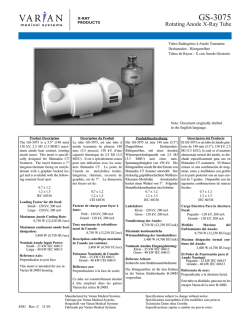
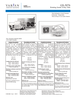
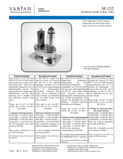
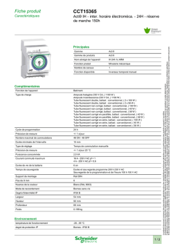
X-RAY
PRODUCTS
GS-3077
Rotating Anode X-Ray Tube
Tubes Radiogénes à Anode Tournante
Drehanoden - Röntgenröhre
Tubos de Rayos-X con Ánodo Giratorio
Note: Document originally drafted in
the English language.
Product Description
Description du Produit
The GS-3077 is a 5.5” (140 mm)
150 kV, 2.5 MJ (3.5 MHU) maximum anode heat content, rotating
anode insert. This insert is specifically designed for CT Scanners.
The insert features a 7° tungstenrhenium facing on molybdenum
with a graphite backed target and is
available with the following nominal focal spot:
Le tube GS-3077, est une tube à
anode tournante de plateau 140 mm,
(5,5 pouces), 150 kV, d’une capacité
therimque de 2,5 MJ (3,5 MUC). Il
est à spécialement concu pour une
utilisation avec les scanners CT. Le
pente de l’anode en molybdéne
traitée, tungsténe, rhènium, recourte
de graphite, est de 7°. La dimension
des foyers est de:
0,8 x 1,5
1,5 x 1,5
CEI 60336
0.8 x 1.5
1.5 x 1.5
IEC 60336
Facteur de charge pour foyer à
fente:
Petit - 120 kV, 100 mA
Grand - 120 kV, 150 mA
Loading Factor for slit focal:
Small - 120 kV, 100 mA
Large - 120 kV, 150 mA
Maximum Anode Cooling Rate:
8,750 W (12,250 HU/sec)
Maximum continuous anode heat
dissipation:
3,400 W (4,760 HU/sec)
Nominal Anode Input Power:
Small - 41 kW IEC 60613
Large - 54 kW IEC 60613
Reference Axis:
Perpendicular to port face.
This insert is intended for use in
Varian B-240H housing.
Toux maximum de refroidissement de l’anode:
8,750 W (12,250 UC/sec)
Produktbeschreibung
Die GS-3077 ist eine 140 mm (5.5”)
Doppelfokus
DrehanodenRöntgenröhre, mit einer Anoden
Wärmespeicherkapazität von 2.5 MJ
(3.5 MHU) und einer max.
Spannungsfestigkeit von 150 kV. Die
Röntgenröhre wurde für den Einsatz an
CT Scanners entwickelt. Der rückseitig graphitbeschichtete Wolfram
Rhenium-Molybdän
Anodenteller
besitzt einen Winkel von 7°. Folgende
Brennfleckkombination ist lieferbar:
0.8 x 1.5
1.5 x 1.5
IEC 60336
Ladefaktor:
Klein - 120 kV, 100 mA
Gross - 120 kV, 150 mA
Nennliestung der Anode:
8,750 W (12,250 HU/sek)
Description calorifique maximim
de l’anode (en continu):
3,400 W (4,760 UC/sec)
Maximale kontinuierliche
Wärmeableitung der Anodentellers:
3,400 W (4,760 HU/sek)
Puissance Nominale de l’anode:
Petit - 41 kW CEI 60613
Grand - 54 kW CEI 60613
Nominale Anoden Eingangsleistung:
Klein - 41 kW IEC 60613
Gross - 54 kW IEC 60613
Référence axe:
Perpendiculaire à la face de sortie.
Referenz Achsen:
Senkrecht zum Strahlenaustrittsfenster.
Ce tube est essentiellement destiné à
être employé dans les gaines Varian
des séries B-240H.
Die Röntgenröhre ist für den Einbau
in die Varian Strahlerhaube B-240H
vorgesehen.
Descripcion del Producto
El GS-3077 es un tubo de ánodo
giratorio de 140 mm (5.5”), 150 kV,
2.5 MJ (3.5 kUC), la cual es el maximo almacenaje termal del anodo, es
diseñado especificamente para
Tomografia Computada y es usado
en CT scannners. El blanco emisor
es una combinación de tungsteno,
renio y molibdeno con grafito en la
parte posterior con un rayo central
de 7 grados. Disponible con las
siguientes combinaciones de marcas
focales:
0.8 x 1.5
1.5 x 1.5
IEC 60336
Carga Electrica Para la Abertura
Focal:
Pequeño - 120 kV, 100 mA
Grande - 120 kV, 150 mA
Medida Maxima del
Enfriamiento del Anodo:
8,750 W (12,250 HU/seg)
Maxima disipación termal continuo del Anodo:
3,400 W (4,760 HU/seg)
El Poder de Penetración para el
Anodo Nominal:
Pequeño - 41 kW IEC 60613
Grande - 54 kW IEC 60613
Referencia de axes:
Perpendicular a la abertura facial.
Este tubo es diseñado, para uso en los
encajes Varian de la serie B-240H.
4582 Rev. E 12/10
Manufactured by Varian Medical Systems
Fabrique par Varian Medical Systems
Hergestellt von Varian Medical Systems
Fabricado por Varian Medical Systems
Specifications subject to change without notice.
Spécifications susceptibles d’être modifiées sans préavis.
Technische Daten ohne Gewähr.
Especificaciones sujetas a cambio sin previo aviso.
GS-3077
X-RAY
PRODUCTS
Volumetric / Helical Scan Ratings IEC 60613
Tableaux des Caractéristiques Nominales de Balayage Volumétrique/Hélicoïdal CEI 60613
Volumen-/Spiralbelichtungs-Leistungdiagramme IEC 60613
Volumétrico/Clasificación Grafica del Escán/Helicoideo IEC 60613
Volume
Scan Time
(Seconds)
3Ø 50 Hz
0.8 x 1.5 Focal Spot 7 Degrees
0,8 x 1.5 Dimension Focale 7 Degrés
0.8 x 1.5 Brennpunkt 7 Grad
0.8 x 1.5 De Marcas Focales 7 Grados
1
2
4
10
20
30
60
Volume
Scan Time
(Seconds)
3Ø 50 Hz
1.5 x 1.5 Focal Spot 7 Degrees
1,5 x 1,5 Dimension Focale 7 Degrés
1.5 x.1.5 Brennpunkt 7 Grad
1.5 x 1.5 De Marcas Focales 7 Grados
3Ø 160 Hz
0.8 x 1.5 Focal Spot 7 Degrees
0,8 x 1,5 Dimension Focale 7 Degrés
0.8 x 1.5 Brennpunkt 7 Grad
0.8 x 1.5 De Marcas Focales 7 Grados
3Ø 160 Hz
Starting H.S. = 34 %
Starting H.S. = 18 %
Starting H.S. = 50 %
120 kV
140 kV 100 kV
100 kV
120 kV
140 kV 100 kV
120 kV
140 kV
225
225
225
225
225
200
200
200
200
200
150
150
150
150
150
225
225
225
225
225
200
200
200
200
200
150
150
150
150
150
225
225
225
225
225
200
200
200
200
200
150
150
150
150
150
225
225
200
200
150
150
225
225 a
200
175 a
150
150 a
225
150 a
200
125 a
150
100 a
MAXIMUM ALLOWED TUBE CURRENT (mA)
AS A FUNCTION OF THE FOLLOWING STARTING HEAT STORAGE AND TUBE VOLTAGES
Starting H.S. = 18 %
Starting H.S. = 34 %
Starting H.S. = 50 %
100 kV
120 kV
140 kV 100 kV
120 kV
140 kV 100 kV
120 kV
140 kV
1
2
4
10
20
325
325
325
325
325
275
275
275
275
275
225
225
225
225
225
325
325
325
325
325
275
275
275
275
275
225
225
225
225
225
325
325
325
325
325
275
275
275
275
250
225
225
225
225
225
30
60
325
275 a
275
225 a
225
200 a
325
225 a
275
175 a
225
150 a
300 a
150 a
250 a
125 a
200 a
100 a
Volume
Scan Time
(Seconds)
MAXIMUM ALLOWED TUBE CURRENT (mA)
AS A FUNCTION OF THE FOLLOWING STARTING HEAT STORAGE AND TUBE VOLTAGES
Starting H.S. = 34 %
Starting H.S. = 18 %
Starting H.S. = 50 %
120 kV
140 kV 100 kV
100 kV
120 kV
140 kV 100 kV
120 kV
140 kV
1
2
4
10
20
350
350
350
350
350
275
275
275
275
275
250
250
250
250
250
350
350
350
350
350
275
275
275
275
275
250
250
250
250
250
350
350
350
350
325
275
275
275
275
275
250
250
250
250
225
30
60
350
275 a
275
225 a
250
200 a
350
225 a
275
175 a
250
150 a
300 a
150 a
250 a
125 a
200 a
100 a
Volume
Scan Time
(Seconds)
1.5 x 1.5 Focal Spot 7 Degrees
1,5 x 1,5 Dimension Focale 7 Degrés
1.5 x 1.5 Brennpunkt 7 Grad
1.5 x 1.5 De Marcas Focales 7 Grados
MAXIMUM ALLOWED TUBE CURRENT (mA)
AS A FUNCTION OF THE FOLLOWING STARTING HEAT STORAGE AND TUBE VOLTAGES
MAXIMUM ALLOWED TUBE CURRENT (mA)
AS A FUNCTION OF THE FOLLOWING STARTING HEAT STORAGE AND TUBE VOLTAGES
Starting H.S. = 18 %
Starting H.S. = 34 %
Starting H.S. = 50 %
100 kV
120 kV
140 kV 100 kV
120 kV
140 kV 100 kV
120 kV
140 kV
1
2
4
10
20
450
450
450
400 b
400 b
375
375
375
350 b
350 b
325
325
325
300 b
300 b
450
450
450
400 b
400 b
375
375
375
350 b
350 b
325
325
325
300 b
300 b
450
450
450
400 b
400 b
375
375
375
350 b
325
325
325
325
300 b
275
30
60
350 b
275 a
300 b
225 a
250 b
200 a
350 b
225 a
300 b
175 a
250 b
150 a
300 a
150 a
250 a
125 a
200 a
100 a
Note:
1. Limits are based on maximum track rat
ing except for the following codes:
a - Limited by available heat storage.
b - Limited by window heating.
c - Limited by filament emission.
2. H.S. = Heat Storage
kV = Tube Voltage
Anmerkungen:
Remarque:
1. Grenwerte basieren auf der maximalen
1. Les limites sont fonction de l’indice
Anodenoberflächenleistung mit
maximal de surface de l’anode, sauf pour
Ausnahme der folgenden Codes:
les codes suivants:
a - Durch verfügbare Wärmekapazität
a - Limité par le stockage thermique
begrenzt.
disponible.
b - Durch Öffnungserwärmung begrenzt.
b - Limité par le chauffage de la fenêtre.
c - Durch Glühfadenemission begrenzt.
c - Limité par le rayonnement des fila2. H.S. = Wärmekapazitat
ments.
kV = Röhre Spannung
2. H.S = Stockage Thermique
kV = Tube Voltage
Nota:
1. La clasificación de la marca maxima son
limitadas, eccepto por los siquientes
codigos:
a - Limitado por el almacenaje de calor
disponible.
b - Limitado por el calor de conducción de
la ventanilla.
c - Limitado por la emisión del filamento.
2. H.S. = Almacenaje de calor
kV = Tubo Voltaje
Note:
Remarque:
Anmerkungen:
Nota:
Rating charts reflect maximim tube performance. Tube operation is ultimately limited
by system software.
Abaques de caractéristiques représentent des
valeurs maximales. L’utilisation du tube est
finalement limitée par le logiciel du système.
Die leistungsdiagramme reflektieren die maximale Röhrenleistung. Der Röhrenbetrieb ist
ultimativ zu begrenzen durch die
Systemkontrollsoftware.
El máximo poder del tubo es reflectada en el
clasificación diagrama. La operación del tubo
es ultimamente limitada por el control del sistema programado.
Copyright © 2010, Varian Medical Systems. All Rights Reserved.
2
GS-3077
X-RAY
PRODUCTS
Cathode Emission Characteristics Charts IEC 60613
3Ø
Caractéristiques d’Émission du Filament CEI 60613
Kathoden - Emissionskennlinien IEC 60613
Caracteristicas de Emissión del Catodo IEC 60613
THREE PHASE EMISSION (± .15 A)
0.8 x 1.5
Filament Voltage (V)
Voltage du Flament (V)
Heizspannung (V)
Voltaje en los Filamentos (V)
Tube Current (mA)
Tube Puissance (mA)
Röhrnstrom (mA)
Tubo de Corriente (mA)
GS-3077
Filament Current (A)
Courant du Filament (A)
Heizstrom (A)
Corriente del Filamento (A)
THREE PHASE EMISSION (± .15 A)
Filament Voltage (V)
Voltage du Flament (V)
Heizspannung (V)
Voltaje en los Filamentos (V)
Tube Current (mA)
Tube Puissance (mA)
Röhrnstrom (mA)
Tubo de Corriente (mA)
GS-3077
Filament Current (A)
Courant du Filament (A)
Heizstrom (A)
Corriente del Filamento (A)
Copyright © 2010, Varian Medical Systems. All Rights Reserved.
3
1.5 x 1.5
GS-3077
X-RAY
PRODUCTS
Le Gaine B-240H
B-240H Housing
Das B-240H Gehäuse
Encaje de B-240H
Maximum Peak Voltage . . . . . . . . . . . . . . . . . . . . . . . . . . . . . . . . . . . . . . . . . . . . . . 150 kV
Anode to Ground . . . . . . . . . . . . . . . . . . . . . . . . . . . . . . . . . . . . . . . . . . . . . . . . . . . . . . 75 kV
Cathode to Ground . . . . . . . . . . . . . . . . . . . . . . . . . . . . . . . . . . . . . . . . . . . . . . . . . . . . 75 kV
Voltage Maximum . . . . . . . . . . . . . . . . . . . . . . . . . . . . . . . . . . . . . . . . . . . . . . . . . . . 150 kV
Tension Anode - Terre . . . . . . . . . . . . . . . . . . . . . . . . . . . . . . . . . . . . . . . . . . . . . . . . . 75 kV
Tension Cathode - Terre . . . . . . . . . . . . . . . . . . . . . . . . . . . . . . . . . . . . . . . . . . . . . . . 75 kV
Maximum X-ray Tube Assembly Heat Content . . . . . . . . . . . 1.5 MJ (2.0 MHU)
Capacité Thermique Maximale de L’Ensemble Tube/Gaine . . . . . 1,5 MJ (2,0 MUC)
Maximum Continuous Heat Dissipation
(max. housing temperature 78°C)
(Includes stator heat) . . . . . . . . . . . . . . . . . . . . . . . . . . . . . . . . 3.7 kW (5.18 kHU/sec)
Dissipation thermique continue de la gaine
(température maximale de la gaine à 78°C)
(Inclut la chaleur statorique) . . . . . . . . . . . . . . . . . . . . . . . . . . 3,7 kW (5,18 kUC/sec)
Maximum Heat Exchanger Dissipation . . . . . . . . . . . . . . . . 5.0 kW (7.0 kHU/sec)
Dissipation Maximale de l’échangeur de chaleur . . . . . . . . . . 5,0 kW (7,5 kUC/sec)
Focal Point Position (Central Ray) Within 1mm
(X, Y Direction from the center of radiation port.)
Position du foyer (rayon central) à 1mm près
(Coordonnées X, Y par rapport au centre du port de rayonnement.)
X-Ray Tube Assembly
Permanent filtration . . . . . . . . . . . . . . . . . . . . . . . . . . . . . . . . . . 1.0 mm Al IEC 60522
Ensemble Radiodène
Filtre non amovible . . . . . . . . . . . . . . . . . . . . . . . . . . . . . . . . . . . 1,0 mm Al CEI 60522
Loading Factors for Leakage Radiation . . . . . . . . . . . . . . . . . . . . . . . 150 kV, 22 mA
Facteur de Charge Poru Rayonement de fuite . . . . . . . . . . . . . . . . . . 150 kV, 22 mA
Federal Standard High Voltage Cable . . . . . . . . . . . . . . . . . . . . . . . . . . . . . . . . . . . . . . 72
Embouts de Cables au Standard Federal . . . . . . . . . . . . . . . . . . . . . . . . . . . . . . . . . . . 72
Ambient Air Temperature Limits for Operation . . . . . . . . . . . . . . . . . . 5°C to 40°C
Température Ambiante Pendant L’usage . . . . . . . . . . . . . . . . . . . . . . . . . . 5°C à 40°C
Temperature Limits for Storage and Transport . . . . . . . . . . . . . . . . -20°C to +75°C
Humidity . . . . . . . . . . . . . . . . . . . . . . . . . . . . . . . . . . . . . . . . . . . . . . . . . . . . +10% to +90%
Atmospheric Pressure Range . . . . . . . . . . . . . . . . . . . . . . . . . . . . . . . 70 kPa to 106 kPa
Limites de Température Pour le Transport et Pour L’Emmasinage
. . . . . . . . . . . . . . . . . . . . . . . . . . . . . . . . . . . . . . . . . . . . . . . . . . . . . . . . . . . . . . -20°C à +75°C
Humidité . . . . . . . . . . . . . . . . . . . . . . . . . . . . . . . . . . . . . . . . . . . . . . . . . . . . . +10% à +90%
Limites de pression atmosphérique . . . . . . . . . . . . . . . . . . . . . . . . . 70 kPa à 106 kPa
Weight: Housing . . . . . . . . . . . . . . . . . . . . . . . . . . . . . . . . . . . . . . . . . . . . 33.1 kg (73 lbs)
Heat Exchanger . . . . . . . . . . . . . . . . . . . . . . . . . . . . . . . . . . . . . . . . . . . . . . 18.2 kg (40 lbs)
Poids: Gaine . . . . . . . . . . . . . . . . . . . . . . . . . . . . . . . . . . . . . . . . . . . . . . . . 33,1 kg (73 lbs)
Échangeur de Chaleur . . . . . . . . . . . . . . . . . . . . . . . . . . . . . . . . . . . . . . . . 18,2 kg (40 lbs)
IEC Classification . . . . . . . . . . . . . . . . . . . . . . . . . . . . . . . . . . . . . . . . . . . . . . . . . . . . Class 1
Classification CEI . . . . . . . . . . . . . . . . . . . . . . . . . . . . . . . . . . . . . . . . . . . . . . . . . . . Classe 1
Safety Devices: Thermal Switch
Normally Closed Contact . . . . . . . . . . . . . . . . . . . . . . . . . . . . . Opening at 85°C ±3°C
Flow Switch - Normally Open contact:
Dispositifs de Sécurité: Switch Thermique
Normalement Fermé . . . . . . . . . . . . . . . . . . . . . . . . . . . . . . . . . Ouverture à 85°C ±3°C
Contacteur de débit - Contact Normalement Ouverture:
Contacts fermés en présence d’un débit d’huil adéfquat.
Contacts close with adequate oil flow.
Filament Frequency Limits . . . . . . . . . . . . . . . . . . . . . . . . . . . . . . . . . . 50 HZ - 25 kHZ
Limites de Fréquence des Filaments . . . . . . . . . . . . . . . . . . . . . . . . . . 50 HZ - 25 kHZ
Power Supply . . . . . . . . . . . . . . . . . . . . . . . . . . . . . . . . . . . . . . . . . . . . . . . . . . . . . . . . . . . . DC
Alimentation Demandée . . . . . . . . . . . . . . . . . . . . . . . . . . . . . . . . . . . . Courant Continu
Maximale Spannungsfestigkeit . . . . . . . . . . . . . . . . . . . . . . . . . . . . . . . . . . . . . . 150 kV
Anode gegen Erde . . . . . . . . . . . . . . . . . . . . . . . . . . . . . . . . . . . . . . . . . . . . . . . . . . . . 75 kV
Kathode gegen Erde . . . . . . . . . . . . . . . . . . . . . . . . . . . . . . . . . . . . . . . . . . . . . . . . . . 75 kV
Voltage Maximo Elevado . . . . . . . . . . . . . . . . . . . . . . . . . . . . . . . . . . . . . . . . . . . . . 150 kV
Anodo a Tierra . . . . . . . . . . . . . . . . . . . . . . . . . . . . . . . . . . . . . . . . . . . . . . . . . . . . . . . . 75 kV
Catodo a Tierra . . . . . . . . . . . . . . . . . . . . . . . . . . . . . . . . . . . . . . . . . . . . . . . . . . . . . . . . 75 kV
Maximo Calor Contenido Ensamblaje del Tubo de Rayos X
. . . . . . . . . . . . . . . . . . . . . . . . . . . . . . . . . . . . . . . . . . . . . . . . . . . . . . . . . . 1.5 MJ (2.0 MHU)
Difusion del calor continuo del encaje
(temperatura máxima de la encaje 78°C)
(Incluye el calor de la bovina) . . . . . . . . . . . . . . . . . . . . . . . . 3.7 kW (5.18 kHU/seg)
Maximale Wärmespeicherdapazität des Strahlergehäuses . . . . 1.5 MJ (2.0 MHU)
Maximale kontinuierliche Wärmeableitung des Strahlergehäuses
(max. Gehäusetemperatur 78°C)
(einschleißlich Statorerwärmung) . . . . . . . . . . . . . . . . . . . 3.7 kW (5.18 kHU/sek)
Maximale Wärmeaustauscher - Verlustleistung . . . . . . . . . . 5.0 kW (7.0 kHU/sek)
Disipación maxima del radiador . . . . . . . . . . . . . . . . . . . . . . . 5.0 kW (7.0 kHU/seg)
Brennfleckposition (Zentralstrahl) innerhalb 1mm.
(X-, Y-Achse von der mitte des Strahlenaustrittsfensters)
Posición de la marca focal (Rayo Central) Dentro de 1mm.
(La Dirección axial X, Y se refiere del centro de la Radiación Portal.)
Röntgenstrahlers
Eigenfilterwert . . . . . . . . . . . . . . . . . . . . . . . . . . . . . . . . . . . . . . 1.0 mm Al IEC 60522
Ensamblaje de Tubos de Rayos X
Filtración Permanente . . . . . . . . . . . . . . . . . . . . . . . . . . . . . . . . 1.0 mm Al IEC 60522
Ladefaktoren für Leckstrahlmessung . . . . . . . . . . . . . . . . . . . . . . . . . 150 kV, 22 mA
Especificaciones de Encaje para la fuga de Radiacion . . . . . . . . . . 150 kV,22 mA
Federal Standard Hochspannungsbuchsen . . . . . . . . . . . . . . . . . . . . . . . . . . . . . . . . . 72
Cable de Receptaculos Comun Federal . . . . . . . . . . . . . . . . . . . . . . . . . . . . . . . . . . . . 72
Umgebungstemperaturgrenzen für den Betrieb . . . . . . . . . . . . . . . . . . . . 5°C bis 40°C
Temperatura Limitada de Operación . . . . . . . . . . . . . . . . . . . . . . . . . . . . . . 5°C a 40°C
Temperaturgrenzen für Aufbewahrung und Transport . . . . . . . . . . -20°C bis +75°C
Feuchtigkeit . . . . . . . . . . . . . . . . . . . . . . . . . . . . . . . . . . . . . . . . . . . . . . . . +10% bis +90%
Luftdruck . . . . . . . . . . . . . . . . . . . . . . . . . . . . . . . . . . . . . . . . . . . . . . . . . 70 kPa bis 106 kPa
Temperatura Limitada de Almacen y Transporte . . . . . . . . . . . . . . . -20°C a +75°C
Humedad . . . . . . . . . . . . . . . . . . . . . . . . . . . . . . . . . . . . . . . . . . . . . . . . . . . . . +10% a +90%
Límites de la presión atmosférica . . . . . . . . . . . . . . . . . . . . . . . . . . . . 70 kPa a 106 kPa
Gewicht: Gehäuse . . . . . . . . . . . . . . . . . . . . . . . . . . . . . . . . . . . . . . . . . . 33.1 kg (73 lbs)
Wärmetauscher . . . . . . . . . . . . . . . . . . . . . . . . . . . . . . . . . . . . . . . . . . . . . 18.2 kg (40 lbs)
Peso: Encaje . . . . . . . . . . . . . . . . . . . . . . . . . . . . . . . . . . . . . . . . . . . . . . . . 33.1 kg (73 lbs)
Radiador . . . . . . . . . . . . . . . . . . . . . . . . . . . . . . . . . . . . . . . . . . . . . . . . . . . . 18.2 kg (40 lbs)
IEC Klassifizierung . . . . . . . . . . . . . . . . . . . . . . . . . . . . . . . . . . . . . . . . . . . . . . . . Klasse 1
Heizfaden - Frequenzgrenze . . . . . . . . . . . . . . . . . . . . . . . . . . . . . . . . . 50 HZ - 25 kHZ
IEC Clasificación . . . . . . . . . . . . . . . . . . . . . . . . . . . . . . . . . . . . . . . . . . . . . . . . . . . . Clase 1
Aparatos de Seguridad: Interruptor Termal
Normalmente Cerrado . . . . . . . . . . . . . . . . . . . . . . . . . . . . . . . . . . Abierto a 85°C ±3°C
Interruptor de Flujo - Normalmente los contactos estan abiertos
Contactos cerrado con a decuado flujo de aceite.
Limites de la frecuencia del filamento . . . . . . . . . . . . . . . . . . . . . . . . 50 HZ - 25 kHZ
Netzanschluß . . . . . . . . . . . . . . . . . . . . . . . . . . . . . . . . . . . . . . . . . . . . . . . . . . . . . . . . . . . . DC
Suministrador-de-Poder . . . . . . . . . . . . . . . . . . . . . . . . . . . . . . . . . . . . Corriente Directa
Sicherheitseinrichtungen: Thermoschalter
normalerweise geschlossen Verbindung: . . . . . . . . . . . . . . . . . Offen bei 85°C ±3°C
Strömungsschalter - Kontakte normalerweise Offen
Kontakte schließen sich bei ausreichendem Ölfluß.
Copyright © 2010, Varian Medical Systems. All Rights Reserved.
4
GS-3077
X-RAY
PRODUCTS
La Gaine B-240H
B-240H Housing
Das B-240H Gehäuse
Dimensions are for reference onlyLes dimensions
Les dimensions sont pour la référence seulement
Maße sind als nur Referenz
Las dimensiones están para la referencia solamente
Copyright © 2010, Varian Medical Systems. All Rights Reserved.
5
Encaje de B-240H
Note: Dimensions in Inches
Remarque: Dimensions en Pouces
Hinweis: Abmessungen in Zoll
Nota: Dimensiones en Pulgadas
X-RAY
PRODUCTS
GS-3077
X-Ray Tube Assembly Heating and Cooling Curves IEC 60613
Abaque de Échauffement Refroidissement de l’ensemble CEI 60613
Röntgenstrahler Erwärmungs- und Abkühlkurven IEC 60613
Curvas de calentamiento y enfriamento de la unidad radiogena IEC 60613
X-ray Tube Assembly Heating and Cooling Curve
Time (Minutes)
Durée (Minutes)
Zeit (Minuten)
Tiempo (Minutos)
Note:
Remarque:
Anmerkungen:
Nota:
1. Heat inputs into housing include tube
power, filament power, and stator power.
1. L’apport calorifique dans la gaine incult la
puissance du tube, du filament et du stator.
2. Heating curves based on no restrictions of
natural convection around tube housing
assembly.
1. Die Erwärmungskurven berücksichtigen
die Verlustleistung aus der Anode, der
Kathode und des Stators.
1. La energia del encaje incluye el poder del
tubo, el poder del filamento y el poder de la
bovina.
2. Courbes d’échauffement basées sur une
circulation d’air naturelle sans entrave autour
de l’ensemble gaine-tube.
3. Heating and cooling curves reflect maximum tube performance. Tube operation is
ultimately limited by system software control.
2. Die Heizkurven basieren auf keinerlei
Einschränkung der natürlichen Konvektion
in der Umgebung der Strahlerhaube.
2. Las curvas de calentamiento no son afectadas por el calor natural creado en la parte
exterior del encaje.
3. Les abaques d’échauffement et de
refroidissement représentent des valeurs
maximales. L’utilisation du tube est finalement limitée par le logiciel du système.
3. Die Angaben stellen die höchstzulassigen
Betriebswerte dar. Der technische Betrieb
muß im Rahmen der Belastungs- und
Abkühlkennlinien erfolgen.
3. El máximo poder del tubo es reflectada en
el diagrama de enfriamiento y calentamiento
del tubo es ultimamente limitada por el control del sistema programado.
Copyright © 2010, Varian Medical Systems. All Rights Reserved.
6
GS-3077
X-RAY
PRODUCTS
Stator Ratings and Characteristics
Spécificités et Caractéristiques du Stator
Statornennleistungen und Merkmale
Caracteristicas y Clarificacion de la Bovina
Terminal / Wire Color Chart
Termiaux / Code Couleru
Klemmen / Drahtfarbentabelle
Maja Del Alambre de Color Impulado / Terminal
Wire Color
Couluers des Branchements
Kabelfarben
Cable de Color
Description
Description
Beschreibung
Descripcion
1
Green
Vert
Grün
Verde
Phase Shift
Changement de Phase
Hilfsphase
Cambio de Fase del Estator
2
Black
Noir
Schwarz
Negro
Phase
Phase
Phase
Fase
3
White
Blanc
Weiss
Blanco
Common
Neutre
Neutral
Común
4
Center Section / Section Centrale /
Mittelteil / Sección Central
5
Green/Yellow
Vert/Jaune
Grün/Gelb
Verde/Amarillo
Housing Ground / Shield
Masse de la Gaine / Blindage
Masse des Gehäuses / Schild
Encaje a Tierra / Armadura
8
White/Black
Blanc/Noir
Weiss/Schwarz
Blanco/Negro
Thermal Switch
Switch Therimque
Thermoschalter
Interruptor Termal
9
Red/Black
Rouge/Noir
Rot/Schwarz
Rojo/Negro
Thermal Switch
Switch Therimque
Thermoschalter
Interruptor Termal
Stator Drive Frequency
Fréquence d'entraînement du stator
Statorantrieb Frequenz
Frecuencia de la impulsión del estator
50 Hz
60 Hz
150 Hz
180 Hz
Stator Type: “R”
Stator Coil Resistance:
Black to White
14 Ω ±15%
Green to White
46 Ω ±15%
Starter Voltage:
50/60 Hz
150/180 Hz
Run
Start
222 VAC 85 VAC
464 VAC 140 VAC
Time to Full Speed:
50/60 Hz
0 - 2700 RPM
150/180 Hz
0 - 7500 RPM
8 Sec.
10 Sec.
X-Ray Tube Assembly:
GS-3077/B-240H
IEC 60601-2-28
Genre Stator: “R”
Résistance de la bobine du stator:
(résistance ohmique)
Noir - Blanc
14 Ω ±15%
Vert - Blanc
46 Ω ±15%
Statortyp: “R”
Stator - Spulenwiderstand
Schwarz - Weiss
14 Ω ±15%
Grün - Weiss
46 Ω ±15%
Spannungen:
50/60 Hz
150/180 Hz
Tension de démarrage:
50/60 Hz 222 alternatif au démarrage
85 alternatif en maintien
150/180 Hz 464 alternatif au démarrage
140 alternatif en maintien
Hochlaufzeit:
50/60 Hz
0 - 2700 U/min
150/180 Hz
0 - 7500 U/min
Temps our atteindre la vitesse maximum:
50/60 Hz de 0 à 2700 trs./mn
8 Sec.
150/180 Hz de 0 à 7500 trs./mn 10 Sec.
Ensemble radiogène:
GS-3077/B-240H
Anlauf
222 VAC
464 VAC
Röntgenstrahler:
GS-3077/B-240H
Weiterlauf
85 VAC
140 VAC
Tipo de la Bovina: “R”
Resistencia del Rollo de la Bovina:
Negro a Blanco
14 Ω ±15%
Verde a Blanco
46 Ω ±15%
Voltage de la Obtenida:
Empezar
222 VAC
464 VAC
50/60 Hz
150/180 Hz
Funcionar
85 VAC
140 VAC
8 Sek.
10 Sek.
Tiempo Para la Velocidad Maxima:
50/60 Hz
0 - 2700 RPM
8 Segundo
150/180 Hz 0 - 7500 RPM 10 Segundo
IEC 60601-2-28
Ensamblaje de Tubo de Rayos X:
GS-3077/B-240H
IEC 60601-2-28
CEI 60601-2-28
Copyright © 2010, Varian Medical Systems. All Rights Reserved.
7
RPM
2800 - 3000
3400 - 3600
8500 - 9000
9500 - 10,800
GS-3077
X-RAY
PRODUCTS
Anode Heating & Cooling Chart
Abaques d’Échauffement et de Refroidissement de L’Anode
Anoden Aufheiz und Abkühlkurven
Curvas de Calentamiento y Enfriamiento del Anodo
Time (Minutes)
Durée (Minutes)
Zeit (Minuten)
Tiempo (Minutos)
Note:
Remarque:
Anmerkungen:
Nota:
1. Heating and cooling curves reflect maximum tube performance. Tube operation is
ultimately limited by system software control.
1. Les abaques d’échauffement et de
refroidissement représentent des valeurs
maximales. L’utilisation du tube est finalement limitée par le logiciel du système.
1. Die Angaben stellen die höchstzulassigen
Betriebswerte dar. Der technische Betrieb
muß im Rahmen der Belastungs- und
Abkühlkennlinien erfolgen.
1. El máximo poder del tubo es reflectada en
el diagrama de enfriamiento y calentamiento
del encaje asamblado. La operación del tubo
es ultimamente limitada por el control del sistema programado.
X-RAY
PRODUCTS
Salt Lake City, UT
1-801-972-5000
www.varian.com
Copyright © 2010, Varian Medical Systems. All Rights Reserved.
8
© Copyright 2026