
CMOS-130 - Kenwood
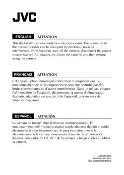
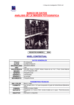
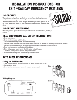
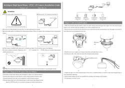
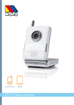
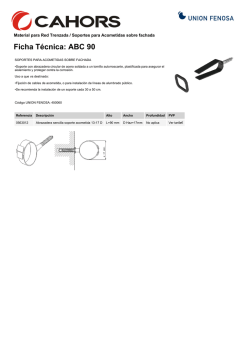
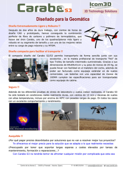
CMOS-130
UNIVERSAL REAR VIEW CAMERA
INSTRUCTION MANUAL
CÁMARA DE VISTA TRASERA UNIVERSAL
MANUAL DE INSTRUCCIONES
B5A-0963-00 [K]
©2015 JVC KENWOOD Corporation
English
Before Use/ Installation Procedure
WARNING
To prevent injury or fire, take the following precautions:
• To prevent a short circuit, never put or leave any metallic objects (such as coins or metal tools) inside the unit.
• Installation and wiring of this product require specialist skill and experience. To assure your safety, please
request a specialist technician to install the unit.
• When you make a hole to install the camera, check the location of pipes, tanks and wiring and avoid touching
them. Otherwise it may cause the fire.
• When you make a hole with a drill, use goggles to protect your eyes.
CAUTION
To prevent damage to the product, take the following precautions:
• Make sure to ground the unit to a negative 12V DC power supply.
• When replacing a fuse, only use a new fuse with the prescribed rating. Using a fuse with the wrong rating may
cause your unit to malfunction.
• Do not use your own screws. Use only the screws provided. If you use the wrong screws, you could damage the
unit.
Installation Procedure
1 To prevent a short circuit, remove the key from the ignition and disconnect the - battery.
2 Make the proper input and output wire connections for each unit.
3 Connect the wiring harness wires in the following order: ground, ignition and camera unit.
4 Install the unit in your car.
5 Reconnect the - battery.
• When humidity is high, dry the surface to which the unit is to be attached before installing.
• Moisture on the attachment surface reduces adhesive strength, which may lead to the unit coming off.
• Do not attach the camera bracket to areas on the car body treated with fluorocarbon resin, or glass.
• May result in the rear view camera falling off.
- Do not apply water to the unit.
- Do not expose the unit to rain.
- Do not subject the camera to unnecessary force.
- Thoroughly clean the area where the adhesive tape attaches to the unit.
• Refer to the instruction manual for details on connecting to the other brand's units, then make connections
correctly.
• Secure the wiring with cable clamps or adhesive tape. To protect the wiring, wrap adhesive tape around them
where they lie against metal parts.
• Route and secure all wiring so it cannot touch any moving parts, such as the gear shift, handbrake and seat
rails.
• Do not route wiring in places that get hot, such as near the heater outlet. If the insulation of the wiring melts
or gets torn, there is a danger of the wiring short-circuiting to the vehicle body.
• When replacing the fuse, be sure to use only fuse with the rating prescribed on the fuse holder.
• To minimize noise locate the TV antenna cable, radio antenna cable and RCA cable as far away from each other
as possible.
• Lay the cords by avoiding high-temperature areas. Use corrugated tubes for wiring inside the engine room. If a
cord contacts a high-temperature area of the vehicle, the coating may melt and cause short-circuiting, which
may lead to a fire or electric shock hazard.
For U.S.A
THIS DEVICE COMPLIES WITH PART 15 OF THE FCC RULES. OPERATION IS
SUBJECT TO THE FOLLOWING TWO CONDITIONS:
(1) THIS DEVICE MAY NOT CAUSE HARMFUL INTERFERENCE, AND (2)
THIS DEVICE MUST ACCEPT ANY INTERFERENCE RECEIVED, INCLUDING
INTERFERENCE THAT MAY CAUSE UNDESIRED OPERATION.
FCC CAUTION
This equipment may generate or use radio frequency energy. Changes or
modifications to this equipment may cause harmful interference unless
the modifications are expressly approved in the instruction manual. The
user could lose the authority to operate this equipment if an unauthorized
change or modification is made.
FCC NOTE
This equipment has been tested and found to comply with the limits for a
Class B digital device, pursuant to Part 15 of the FCC Rules. These limits are
designed to provide reasonable protection against harmful interference in
a residential installation. This equipment may cause harmful interference
to radio communications, if it is not installed and used in accordance with
the instructions. However, there is no guarantee that interference will not
occur in a particular installation. If this equipment does cause harmful
interference to radio or television reception, which can be determined by
turning the equipment off and on, the user is encouraged to try to correct
the interference by one or more of the following measures:
• Reorient or relocate the receiving antenna.
• Increase the separation between the equipment and receiver.
• Connect the equipment into an outlet on a circuit different from that to
which the receiver is connected.
• Consult the dealer or an experienced radio/TV technician for help.
Accessories
Camera [with camera bracket (A)] ..........1
Grommet..........1
Camera bracket clamping screw..........1
FUSE ..........1
Camera bracket (B)..........1
WARNING
• If you connect the ignition wire (Red) to the car chassis (Ground), you may cause a short circuit, that in turn
may start a fire. Always connect those wires to the power source running through the fuse box.
• Do not cut out the fuse from the ignition wire (Red). The power supply must be connected to the wires via the
fuse.
CAUTION
• If your car’s ignition does not have an ACC position, connect the ignition wires to a power source that can be
turned on and off with the ignition key. If you connect the ignition wire to a power source with a constant
voltage supply, as with battery wires, the battery may be drained or affected.
• If the fuse blows, first make sure the wires aren’t touching to cause a short circuit, then replace the old fuse
with one with the same rating.
• Insulate unconnected wires with vinyl tape or other similar material. To prevent a short circuit, do not remove
the caps on the ends of the unconnected wires or the terminals.
• After the unit is installed, check whether the brake lamps, blinkers, wipers, etc. on the car are working
properly.
• Install the unit so that it does not obstruct the rear field of view.
• Install the unit so that it does not protrude from the side of the car.
• Do not perform installation in the rain or fog.
Installation
For Canada
CAN ICES-3(B)/NMB-3(B)
Connections
Recommended Installation Position
Examples of correct camera installation on the rear of the
vehicle
7
8
Complete all of the required connections.
Display the camera video.
Basic Connections
Before viewing the camera, apply the parking brake and chock the wheels
so that the vehicle will not move. Otherwise, an unexpected accident may
result.
For displaying the camera video, read the instruction manual for your video
monitor.
Installation position
Change the shift lever to the R (Reverse) range to view the
image of the rear of the vehicle.
9 Adjust the camera angle.
Connect to the rearview camera video input or to the external
video input of the video monitor.
Video cord (commercially available)
Navigation system/video monitor (commercially available)
When adjusting the camera angle, be careful not to stretch the camera cord.
Adjust the angle so that the rear of the vehicle or the bumper can be seen at
the bottom of the monitor.
Mount so that the “KENWOOD”
logo appears at the top.
Video out
Camera
Engine key
Fuse (2A)
Installing the Camera/Adjusting its angle
1
2
3
10After adjusting the camera angle, tighten the retaining
Using a commercially available cleaner, wipe dirt, moisture and oil away
from the surface on which the camera bracket is to be attached.
11Fix the camera firmly in position.
Loosen the camera bracket retaining screws.
Using a commercially available
Phillips screwdriver, loosen the
two retaining screws.
4
Perform steps 4 and 5 only when they are required.
If required, separate the camera bracket from the camera
and adjust the shape according to the surface on which it
will be attached.
Bend
Camera bracket (A) Bend
5
6
Adjust the camera bracket
shape so that it fits the
camera installation
position.
Mount the camera on the camera bracket.
Mount so that the “KENWOOD” logo appears at the top.
Fix the camera temporarily with tape, etc.
Using a piece of tape, etc., fix the camera temporarily.
12345
Install the camera at the center of the vehicle and not to hide the number
plate. Install the camera straight toward the forward/reverse direction of the
vehicle. Be careful not to lean the camera as it will effect the viewing image.
B5A-0963-00_A3.indd 1
Accessory cord (Red)
Vehicle rear part or bumper
Decide the camera installation position.
Clean the camera installation surface.
Camera’s cord length: 75cm (2.46 feet)
screws firmly.
Inspect the retaining screws at times. If they are loose, tighten them firmly.
Peel off the paper liner from the double-side adhesive tape on the camera
bracket and attach it. After attaching, push the camera bracket with your
finger to ensure close adhesion.
Do not touch the adhesive surface with your hand or peel and reattach an
attached tape, as these will degrade the adhesive force and may cause the
camera bracket to be detached. If required, secure the bracket on the vehicle
body using the camera bracket clamping screw.
The camera bracket has two holes for the screw. Select one of them to fit the
position of the attachment.
Camera bracket clamping screw
(M3 x 8mm)
Accessory power (ACC) Fuse
Connect to the ON-OFF switchable power
supply. Do not connect to a permanently ON
power supply.
Main fuse
GND cord (Black)
Connect to a metallic part of vehicle (a part of chassis
connected to the negative side of power supply).
GND
Battery
CAUTION
• If the engine key of your vehicle does not have the ACC position, connect the red wire to a power source that is active when
the key is ON position.
• Before proceeding to connections, make sure that the engine key is not inserted and disconnect the (-) terminal of the
battery to prevent a possible short circuit.
Specifications
Camera Unit
Output video
: Wide-angle mirror image (for rearview)
Sensor: 1/4-inch color CMOS sensor
Number of pixels: Approx. 380,000 pixels
Lens
: Wide angle, Focal length f=1.12 mm, F value 2.2
Angles of view
: Horizontal: Approx. 129°
: Vertical: Approx. 104°
Video output: 1.0 Vp-p/ 75Ω
Illumination range: Approx. 0.9 to 100,000 lux
Iris system: Electronic iris
Scanning system: Interlace
Synchronizing system: Internal synchronization
Dimensions (WxHxD): 23.4 x 23.4 x 23.9 mm
Weight: Approx. 21 g (without cable)
General
Operating voltage: 14.4V (9.0 V – 16.0 V)
Max. current consumption : 60 mA
• Mirror image means that the video image inverts the left and right just
like the image seen on the rearview mirror or a side mirror.
• Specifications subject to change without notice.
2015/12/11 9:46
Español
Antes de utilizar/procedimiento de instalación
ADVERTENCIA
Para evitar lesiones o incendios, tome las precauciones siguientes:
• Para evitar cortocircuitos, nunca coloque ni deje objetos metálicos (por ejemplo, monedas o herramientas
metálicas) dentro de la unidad.
• La instalación y el tendido de cables de esta unidad requieren de la habilidad y experiencia de un especialista.
Por motivos de seguridad, pida a un técnico especialista que instale la unidad.
• Al realizar un orificio para instalar la cámara, compruebe la ubicación de las tuberías, los depósitos y el
cableado para evitar tocarlos. De lo contrario, podría ocasionar un incendio.
• Al realizar un orificio con un taladro, utilice gafas para protegerse los ojos.
PRECAUCIÓN
Para evitar daños en la unidad, tome las siguientes precauciones:
• Asegúrese de utilizar para la unidad una fuente de alimentación de 12V CC con conexión a tierra negativa.
• Cuando reemplace un fusible, utilice únicamente un fusible nuevo del régimen prescrito. El uso de un fusible
de régimen incorrecto podría ocasionar un funcionamiento defectuoso de la unidad.
• No utilice sus propios tornillos. Utilice solo los tornillos suministrados. El uso de tornillos diferentes podría
causar daños en la unidad.
Procedimiento de instalación
1 Para prevenir cortocircuitos, retire la llave de encendido y desconecte la batería -.
2 Realice de forma adecuada las conexiones de cables de entrada y salida para cada unidad.
3 Conecte los cables del mazo de cables en el siguiente orden: cable a tierra, encendido y unidad de
la cámara.
4 Instale la unidad en el automóvil.
5 Conecte nuevamente la batería -.
• No lleve a cabo la instalación cuando llueva o haya niebla.
• Si hay mucha humedad, seque la superficie donde se colocará la unidad antes de realizar la instalación.
• La humedad en la superficie del dispositivo de sujeción reduce la fuerza adhesiva, y la unidad podría soltarse.
• No coloque la abrazadera de la cámara en áreas de la carrocería del automóvil que hayan sido tratadas con
resina fluorocarbonada o cristal.
• Podría provocar que la cámara de vista trasera se caiga.
- No aplique agua a la unidad.
- No exponga la unidad a la lluvia.
- No someta la cámara a fuerza innecesaria.
- Limpie bien donde se haya utilizado cinta adhesiva para pegar en la unidad.
• Remítase al Manual de instrucciones para más detalles sobre la conexión de otras unidades; luego, realice las
conexiones correctamente.
• Asegure el tendido de cables con abrazaderas de cable o cinta adhesiva. Para proteger el tendido de cables,
póngales cinta adhesiva alrededor contra partes metálicas.
• Coloque y asegure todo el tendido de cables de forma que no pueda tocar ninguna parte en movimiento, tal
como el eje de engranajes, freno de mano y los raíles del asiento.
• No coloque el tendido de cables en lugares que se calientan, tales como la salida del calentador. Si el
aislamiento del tendido de cables se derrite o se rompe, hay peligro de cortocircuito del tendido de cables con
la carrocería.
• Cuando reemplace un fusible, asegúrese de utilizar únicamente un fusible del régimen prescrito en el
portafusibles.
• Para minimizar el ruido coloque el cable de la antena de TV, de la antena de radio y del RCA lo más lejos posible
uno del otro.
• Tienda los cables evitando las áreas con altas temperaturas. Utilice tubos acanalados para cablear los cables
dentro del compartimiento del motor. Si un cable entra en contacto con una zona del vehículo que está a
alta temperatura, el revestimiento podría derretirse y provocar un cortocircuito, lo que podría provocar un
incendio o peligro de descarga eléctrica.
Información acerca de la eliminación de equipos eléctricos y electrónicos
al final de la vida útil (aplicable a los países que hayan adoptado sistemas
independientes de recogida de residuos)
Los productos con el símbolo de un contenedor con ruedas tachado no
podrán ser desechados como residuos domésticos. Los equipos eléctricos y
electrónicos al final de la vida útil, deberán ser reciclados en instalaciones que
puedan dar el tratamiento adecuado a estos productos y a sus subproductos
residuales correspondientes. Póngase en contacto con su administración
local para obtener información sobre el punto de recogida más cercano.
Un tratamiento correcto del reciclaje y la eliminación de residuos ayuda a
conservar los recursos y evita al mismo tiempo efectos perjudiciales en la
salud y el medio ambiente.
Accesorios
Cámara [con abrazadera (A)] ..........1
Arandela..........1
Tornillo de apriete de la abrazadera de la cámara ..........1
Fusible..........1
Abrazadera de la cámara (B)..........1
ADVERTENCIA
• Si conecta el cable del encendido (rojo) al chasis del automóvil (a tierra), puede dar lugar a un cortocircuito
pudiendo causar un incendio. Conecte siempre esos cables a la fuente de alimentación que pasa por la caja de
fusibles.
• No desconecte el fusible desde el cable de encendido (rojo). El suministro de alimentación debe estar
conectado a los cables a través del fusible.
PRECAUCIÓN
• Si el encendido de su automóvil no dispone de posición CA, conecte los cables de encendido a la fuente de
alimentación que pueda activarse y desactivarse con la llave de encendido. Si conecta el cable de encendido
a una fuente de alimentación con un suministro de voltaje constante, como con los cables de la batería, la
batería puede agotarse.
• Si se funde el fusible, en primer lugar asegúrese de que los cables no hayan causado un cortocircuito, y luego
reemplace el fusible usado por otro del mismo régimen.
• Enrolle los cables no conectados con una cinta de vinilo u otro material similar para que queden aislados. Para
evitar cortocircuitos, no retire las tapas de los extremos de los cables o terminales no conectados.
• Después de instalar la unidad, compruebe que las lámparas de freno, las luces intermitentes, el
limpiaparabrisas, etc. funcionen satisfactoriamente.
• Instale la unidad de forma que no obstruya el campo de vista trasero.
• Instale la unidad de forma que no sobresalga por el costado del automóvil.
Instalación
Conexiones
Posición de instalación recomendada
Ejemplos de una instalación correcta de la cámara en la parte
trasera del vehículo
7
8
Realice todas las conexiones necesarias.
Muestre el vídeo de la cámara.
Conexiones básicas
Antes de ver la cámara, aplique el freno de estacionamiento y ponga una
cuña en las ruedas para que el vehículo permanezca inmóvil. Si no lo hace,
podría producirse un accidente inesperado.
Para mostrar el vídeo de la cámara, lea el manual de instrucciones del
monitor de vídeo.
Posición de instalación
Conéctela a la entrada de vídeo de la cámara de vista trasera o
a la entrada de vídeo externa del monitor de vídeo.
Ponga la palanca de cambio en la relación R (marcha atrás)
para ver la imagen de la parte posterior del vehículo.
9 Ajuste el ángulo de la cámara.
Al ajustar el ángulo de la cámara, procure no tirar del cable de la cámara.
Ajuste el ángulo de forma que pueda verse la parte trasera del vehículo o el
parachoques en la parte inferior del monitor.
Móntela de modo que el logotipo
"KENWOOD" quede en la parte
superior.
Instalación de la cámara/ajuste de su ángulo
1
2
3
Decida cuál será la posición de instalación de la cámara.
Limpie la superficie de instalación de la cámara.
Utilizando un jabón disponible en el mercado, limpie la suciedad, la
humedad y el aceite de la superficie donde acoplará la abrazadera de la
cámara.
Afloje los tornillos de fijación de la abrazadera de la
cámara.
Con un destornillador Phillips
disponible en el mercado, afloje
los dos tornillos de retención.
4
Realice los pasos 4 y 5 solo si es necesario.
Si es necesario, separe la abrazadera de la cámara y ajuste
su forma según la superficie donde se acoplará.
Doblar
Doblar
Abrazadera de la cámara (A)
5
6
Ajuste la forma de la
abrazadera de la cámara
de modo que se acople a
la posición de instalación
de la cámara.
Monte la cámara sobre la abrazadera.
Móntela de modo que el logotipo "KENWOOD" quede en la parte superior.
Fije la cámara provisionalmente con cinta o un material
similar.
Con un trozo de cinta o un material similar, fije la cámara provisionalmente.
12345
Instale la cámara en el centro del vehículo sin ocultar la matrícula. Instale
asimismo la cámara recta en la dirección de avance/retroceso del vehículo.
Procure no inclinar la cámara hacia otras direcciones del vehículo, etc.
B5A-0963-00_A3.indd 2
Cable de vídeo (disponibles en el mercado)
Sistema de navegación/monitor de vídeo (disponibles en el mercado)
Salida de vídeo
Cámara
Fusible (2 A)
Parte trasera del vehículo o parachoques
Examine los tornillos de fijación de vez en cuando. Si están flojos, apriételos
con firmeza.
Longitud del cable de la cámara: 75cm (2.46 pies)
11Fije la cámara firmemente en su posición.
Retire la protección de papel de la cinta adhesiva de doble cara de la
abrazadera de la cámara y pegue la cinta. Después de pegarla, empuje
la abrazadera de la cámara con el dedo para comprobar que esté bien
adherida.
No toque la superficie adhesiva con la mano y no retire y vuelva a pegar una
cinta ya adherida, ya que la fuerza adhesiva se verá reducida y la abrazadera
de la cámara podría desengancharse. Si es necesario, fije la abrazadera a la
carrocería del vehículo utilizando el tornillo de fijación de la abrazadera de
la cámara.
El soporte de la cámara presenta dos orificios para el tornillo. Seleccione uno
de ellos para ajustar la posición del accesorio.
Llave del motor
Cable accesorio (rojo)
10Después de ajustar el ángulo de la cámara apriete
firmemente los tornillos de fijación.
Alimentación de los
accesorios (ACC) Fusible
Conecte la unidad a la fuente de
alimentación conmutable ON-OFF.
No conecte la unidad a una fuente de
alimentación permanentemente encendida.
Fusible principal
Cable de tierra (negro)
Conecte la unidad a una parte metálica del
vehículo (una parte del chasis conectada al lado
negativo de la fuente de alimentación).
Masa
Batería
PRECAUCIÓN
• Si la llave del motor de su vehículo no incluye la posición ACC, bifurque el cable activado cuando la llave del motor esté en
posición ON y conéctelo al cable de alimentación del accesorio.
• Antes de realizar las conexiones, compruebe que la llave del motor no esté introducida y desconecte el terminal (-) de la
batería para evitar que se produzcan cortocircuitos.
Tornillo de fijación de la abrazadera
de la cámara (M3 x 8 mm)
Especificaciones
Unidad de la cámara
Salida de vídeo
: Imagen especular gran angular (para vista trasera)
Sensor: Sensor CMOS de color de 1/4-pulgadas
Número de píxeles: A prox. 380.000 píxeles
Lente
: Gran angular, Longitud focal f=1,12 mm,
Valor F 2,2
Ángulos de visión
: Horizontal: Aprox. 129°
: Vertical: Aprox. 104°
Salida de vídeo: 1,0 Vp-p/ 75Ω
Rango de iluminación: Aprox. 0,9 a 100.000 lux
Sistema del iris: Iris electrónico
Sistema de escaneo: entrelazado
Sistema de sincronización: Sincronización interna
Dimensiones (Anch x Alt x Prof)
: 23,4 x 23,4 x 23,9 mm
Peso: Aprox. 21 g (sin cable)
General
Tensión de funcionamiento: 14,4V (9,0 V – 16,0 V)
Máx. consumo de corriente: 60 mA
• Una imagen especular es una imagen de vídeo en la que el lado izquierdo
y el derecho se invierten como en la imagen vista en un retrovisor trasero
o lateral.
• Las especificaciones se encuentran sujetas a cambios sin previo aviso.
2015/12/11 9:46


© Copyright 2026