
2L-5054-00 (T8561) English Manual.CDR
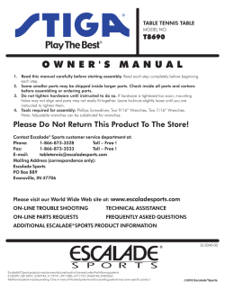
TABLE TENNIS TABLE
MODEL NO.
T8561
OWNER’S
MANUAL
1. Read this manual carefully before starting assembly. Read each step completely before beginning
each step.
2. Some smaller parts may be shipped inside larger parts. Check inside all parts and cartons
before assembling or ordering parts.
3. Do not tighten hardware until instructed to do so. If hardware is tighten too soon, mounting holes
may not align and parts may not easily fit together. Leave locknuts slightly loose until you are instructed to
tighten them.
4. Tools required for assembly: Phillips Screwdriver, Adjustable Wrenches, Rubber Hammer, 8mm Wrench,
and 10mm wrench.
5. To make assembly as easy as possible, place all parts of the table in a cleared area and remove the packaging
material. Do not remove parts from bags until you are ready to assemble that part. Do not dispose of the
packing material until assembly is completed. For help in identifying parts, use the the Parts List, Hardware
Identification and the Exploded Drawings.
6. An electric screwdriver is helpful in assembly. However, please set at low torque and use caution because you
could overtighten the hardware and strip the screws.
Please Do Not Return This Product To The Store!
Contact Escalade Sports customer service department at:
Phone:
1-866-873-3528
Toll-Free!
Fax:
1-866-873-3533
Toll-Free!
E-mail:
[email protected]
Mailing Address(correspondence only):
Escalade Sports
PO box 889
Evansville, IN 47706
R
Please visit our World Wide Web site at: www.escaladesports.com
ON-LINE TROUBLE SHOOTING
TECHNICAL ASSISTANCE
ON-LINE PARTS REQUESTS
FREQUENTLY ASKED QUESTIONS
ADDITIONAL ESCALADE SPORTS PRODUCT INFORMANTION
2L-5054-00
Escalade Sport products may be manufactured and/or licensed under the following patents.
6120397, 5816957, 5769744, 5119741, 4911085, 4717157, D460140, D420563
Additional patents may be pending. One or more of the listed patents and/or pending patents may cover specific product.
R
C
2012 Escalade Sports
R
THREE YEAR LIMITED WARRANTY
This consumer warranty extends to the original consumer purchase of any ESCALADE® SPORTS Product
(hereinafter referred as the "Product").
WARRANTY DURATION: This Product is warranted to the original consumer purchase of a period of three (3) years from the original
purchase.
WARRANTY COVERAGE: ESCALADE SPORTS warrants to the original Consumer Purchaser that any Product of its manufacture is free
from defects in material and workmanship when used for the intended purpose under normal use and conditions. THIS WARRANTY IS
VOID IF THE PRODUCT HAS BEEN DAMAGED BY ACCIDENT, UNREASONABLE USE, NEGLIGENCE, IMPROPER SERVICE, FAILURE TO
FOLLOW INSTRUCTIONS PROVIDED WITH THE PRODUCT OR OTHER CAUSES NOT ARISING OUT OF DEFECTS IN MATERIAL
AND WORKMANSHIP.
WARRANTY PERFORMANCE: During the above three (3) year warranty period, ESCALADE SPORTS shall repair or replace with a
comparable model, and/or Product, or component thereof, for any product which may prove defective under normal use and proper care, and
which our examination shall disclose to our satisfaction to be thus defective, please contact our Warranty Dept.
1-866-873-3528 / Warranty Dept.
Or Write us at:
Escalade® Sports, Inc. - P.O. Box 889, Evansville, IN 47706 - Attn: Warranty Dept.
Or E-mail us at:
[email protected]
Other than shipping requirements no charge will be made for such repair or replacement of in-warranty Products. ESCALADE®
SPORTS strongly recommends that the Product is insured for value prior to mailing.
WARRANTY DISCLAIMERS: ANY IMPLIED WARRANTIES ARISING OUT OF THIS SALE, INCLUDING BUT NOT LIMITED TO THE
IMPLIED WARRANTIES OF MERCHANTABILITY AND FITNESS FOR A PARTICULAR PURPOSE, ARE LIMITED IN DURATION TO THE
ABOVE THREE (3) YEAR WARRANTY PERIOD. ESCALADE® SPORTS SHALL NOT BE LIABLE FOR LOSS OF USE OF THE PRODUCT
OR OTHER CONSEQUENTIAL OR INCIDENTAL COSTS, EXPENSES OR DAMAGES INCURRED BY THE CONSUMER OF ANY
OTHER USE.
Some states do not allow the exclusion or limitation of implied warranties or consequential or incidental damages, so the above
limitations or exclusions may not apply to you.
LEGAL REMEDIES: This warranty gives you specific legal rights and you may also have other rights which may vary from state to
state.
CAUTION
THIS IS A TABLE TENNIS TABLE. DO NOT SIT, STAND, LEAN, WALK OR JUMP ON TABLE!
FAILURE TO COMPLY WITH THIS CAUTION COULD RESULT IN PERSONAL INJURY AND/OR
PROPERTY DAMA GE!
UNLEVEL FLOORS
If table does not seem level, it is probably because floor is not level. Move table several inches (set table in
playing position) in different directions to find the best location for the table. If the floor is extremely
unlevel, table may not play or operate properly. If table is high in the center, shim up under the outer legs.
CARE AND MAINTENANCE
You have purchased a quality product that will give you years of enjoyment. By following these simple maintenance steps you will add to the life of your new table.
The top (playing surface) of your table is of aluminum construction. It can be affected by atmospheric conditions, meaning both temperature and humidity. This
may cause a slight sag or distortion as top expands or contracts. This is normal and should not cause concern as it does not detract from the play or utility value
of the table.
STORAGE OF YOUR TABLE
Wind gusts can blow over or unexpectedly open the table; Store in protected area. When your table is not in use, it should be folded up in a dry area.
CLEANING YOURTABLE
To clean your table use a soft damp NOT WET cloth only. To prevent damage to your table's playing surface DO NOT use any chemicals, abrasive, or cleaning
products on your table's playing surface.
IMPORTANT: Periodically, lubricate all moving parts, including pivot points, to assure smooth opening and closing.A light lubricant such as WD-40 is recommended.
2
HARDWARE IDENTIFICATION
10
12
1/4-20 X 2 1/4 Phillips Rd. Hd. Bolt (4 pieces)
1/4-20 X 2 Carriage Bolt (4 pieces)
28
17
#10-24 X 3/4 Thumb
Screw (4 pieces)
#10-24 X 2" Phillips Rd. Hd. Bolt (4 pieces)
16
15
#8-32 X 1 1/4 Phillips Rd. Hd. Sms (8 pieces)
#8 X 5/8 Phillips Rd. Hd. Sms (100 pieces)
11
26
1/2 OD X .281 ID X 3/4 Long
Plastic Spacer (4 pieces)
#10 Washer (8 pieces)
19
#10-24 Locknut (4 pieces)
13
3/4 OD X1/4 ID X 1/16 Thick Flat
Plastic Washer (4 pieces)
14
33
3/4 OD X1/4 ID X 1/8 Thick Flat
Plastic Washer (4 pieces)
3
1/4-20 Locknut (8 pieces)
1. Slide a Caster Wheel with Lock (#30) into Caster Beam
as shown in FIGURE 1. On the other end of the Caster
Beam attach a Caster Wheel without Lock (#9).
Make sure you have one Caster Wheel with lock and a
Caster Wheel without lock for each Caster Beam.
Repeat this step to attach the Casters to the second
Caster Beam.
Parts Needed:
2 pcs - #8 Caster Beam
2 pcs - #9 Caster without lock
2 pcs - #30 Caster with lock
READ AND FOLLOW ALL ASSEMBLY, OPERATING,
AND SAFETY INSTRUCTIONS CAREFULLY . AT LEAST
TWO (2) ADULTS ARE NEEDED TO PUT THIS TABLE
TOGETHER!
8
30
8
without
lock
with lock
Rubber Hammer
8
9
NOTE:
Make sure the Caster
Stem is completely installed
into Caster Beam as shown.
without lock
9
9
with lock
Figure 1
30
30
2. Attach Cross Tube (#7) to Caster Beam Assemblies using four Thumb Screws (#28) as shown
in FIGURE 2. Tighten bolts snug but DO NOT over tighten.
Parts Needed:
1 pc - #7 Cross Tube
Hardware Needed:
4 pcs - #28 #10-24 Thumb Screw
7
28
4
Figure 2
3. Attach four Strut Tubes (#4) to Caster Beam Assembly
with four Carriage Bolts (#10) and four Locknuts (#14)
as shown in FIGURE 3. Tighten nuts snug but DO NOT
over tighten.
Hardware Needed:
4 pcs - #10 Carriage Bolt
4 pcs - #14 Locknut
READ AND FOLLOW ALL ASSEMBLY, OPERATING,
AND SAFETY INSTRUCTIONS CAREFULLY. AT LEAST
TWO (2) ADULTS ARE NEEDED TO PUT THIS TABLE
TOGETHER!
Parts Needed:
4 pcs - #4 Strut Tube
4
14
Figure 3
10
NOTE:
Snug, but DO NOT over-tighten these four pivot points.
5
4. A) Attach two 1" Plastic Clips (#23) to bottom of aluminum top assembly using four Screws (#15) as
shown in FIGURE 4 and DETAIL B.
B) Attach U-Leg (#1) with two 1-1/2" Plastic Tube Brackets (#27) as shown in FIGURE 4 and
DETAIL A. Attach with twelve Screws (#15). CAUTION: Slots in Plastic Tube Brackets (#27)
must face toward middle of table exactly as shown or the table will not operate properly.
C) Attach U-Support (#3) with two 1" Plastic Tube Brackets (#24) as shown in DETAIL B. Attach with
twelve Screws (#15). CAUTION: slots in Plastic Tube Brackets (#24) must face toward middle
of table exactly as shown or the table will not operate properly.
D) Rotate U-Leg (#1) and U-Support (#3) until you see the screw hole in the slot of Tube Bracket (#27)
and (#24). Slide U-Leg and U-Support side to side if necessary to see hole. See DETAIL A & B.
E) Thread two Screws (#16) through slot in Plastic Tube brackets (#24) & into U-Support (#3) and two
Screws (#16) through slot in Plastic Tube Brackets (#27) & into U-Leg (#1) as shown in DETAIL A & B.
F) Slide two Plastic Leg Caps (#20) onto ends of U-Leg (#1).
Parts Needed:
Hardware Needed:
28 pcs - #15 Phillips Rd. Hd. Screw
4 pcs - #16 Phillips Rd. Hd. Screw
Tube Bracket Slots
DETAIL A
1 pc - #1 U-Leg-Silver
1 pc - #2 Aluminum Top Assembly
1 pc - #3 U-Support-Silver
2 pcs - #20 Plastic Leg Cap
2 pcs - #23 1” Plastic Clip
2 pcs - #24 1’’ Plastic Tube Bracket
2 pcs - #27 1-1/2” Plastic Tube Bracket
1
DETAIL B
16
15
24
27
15
20
1
3
16
NOTE: Tighten screws snug,
but do not overtighten, causing
screws to strip in metal tube.
16
15
23
15
3
27
2
16
24
Figure 4
23
Middle of table is
end without stripe.
NOTE: All Tube Bracket Slots face toward
middle of the table. As shown in Figure 4.
6
5. A) Attach one LH short Hinge & Mounting Bracket Assembly (#18) using four Screws (#15) as shown in
DETAIL C. Attach one RH short Hinge & Mounting Bracket Assembly (#6) using four Screws (#15) as
shown in FIGURE 5. Attach two Long Hinge & Mounting Bracket Assemblies (#5) using eight Screws
(#15) as shown in DETAIL D & FIGURE 5.
B) Attach LH short Hinge & Mounting Bracket Assembly (#18) and RH short Hinge & Mounting Bracket
Assembly (#6) to U-Leg (#1) using two Bolts (#17) with two Thick Flat Plastic Washers (#33) and two
Locknuts (#19) as shown in FIGURE 5 and DETAIL C. DO NOT OVERTIGHTEN hinge must pivot.
Note: 1/8” Thick Plastic Washer (#33) goes between Hinge and Leg.
REPEAT STEPS 4-5 ON THE OTHER ALUMINUM TOP ASSEMBLY.
CAUTION: Hinges must be positioned
Parts Needed:
exactly as shown or table will not operate 1 pc - #6 RH short Hinge & Mounting Bracket Assembly
correctly and could be damaged.
1 pc - #18 LH short Hinge & Mounting Bracket Assembly
Do not overtighten nuts, hinge must pivot. 2 pcs - #5 Long Hinge & Mounting Bracket Assembly
33
(Thick Washer)
33
Hardware Needed:
16 pcs - #15 Phillips Rd. Hd. Screw
2 pcs - #17 Phillips Rd. Hd. Bolt
2 pcs - #19 Locknut
2 pcs - #33 Flat Plastic Washer (1/8” Thick)
6. Attach table top to base assembly. Pivot Strut Tubes (#4)
up and then with at least one adult on each side of table
top, lift top and align ends of U-support Tube (#3) with
tops of strut tubes on caster beams as shown in
FIGURE 6.
Slide tubes together. Repeat for other Table Top.
AT LEAST TWO (2) ADULTS ARE NEEDED TO
COMPLETE THE REST OF THIS ASSEMBLY! WHEN
ASSEMBLING TOPS TO BASE, HANDLE TOP
ASSEMBLIES BY GRASPING ONLY THE TOPS
THEMSELVES. DO NOT GRASP METAL LEGS, USUPPORT, LINKAGE, OR HINGES. THESE PARTS
CAN MOVE AND COULD PINCH FINGERS OR
HANDS CAUSING SERIOUS INJURY! ASSEMBLE
AS SHOWN WITH LEGS FULLY CLOSED AND
TOPS IN A VERTICAL POSITION. DO NOT OPEN
LEGS AND TRY TO ASSEMBLE. TABLE TOPS ARE
HEAVY - DO NO T ATTEMPT TO ASSEMBLE
ALONE!
DO NOT OPEN THE TABLE TO PLAYING POSITION
UNTIL BOTH TOPS ARE INSTALLED! DO NOT LEAVE
TABLE STANDING UNATTENDED. IT COULD BE
KNOCKED OVER CAUSING SERIOUS BODILY INJURY
OR PROPERTY DAMAGE.
3
Figure 6
4
NOTE: PIVOT STRUT TUBES UP AS SHOWN.
8
7. Attach U-Support (#3) and Strut Tubes (#4) using two Screws (#15) as shown in FIGURE 7.
Note: If hinge (#5) is positioned as shown in DETAIL E, you will have to rotate the hinge to the position shown in
Detail F. DO NOT unscrew the hinge, you can rotate the hinge without unscrewing it from the table. If you want to
see a video on how to position Hinge (#5) go to: http://www.escaladesports.com/customer-service/videos.html
8. Attach Long Hinge & Mounting Bracket Assemblies (#5) to Strut Tubes (#4) using two Bolts (#12), two Spacers (#11),
two Flat Plastic Washers (#13) and two LockNuts (#14) as shown in FIGURE 7 and DETAIL F.
Tighten Nuts snug, but DO NOT OVERTIGHTEN, hinges must pivot.
9. Attach two Corner Protectors (#25) to Top Assembly using four Screws (#15) with four Washers (#26) as shown in FIGURE 7.
Repeat for other Table Top.
Part Needed:
Hardware Needed:
2 pcs - #25 Corner Protector
2 pcs - #11 Spacer
2 pcs - #12 Phillips Rd. Hd. Bolt
2 pcs - #13 Flat Plastic Washer
2 pcs - #14 LockNut
6 pcs - #15 Phillips Rd. Hd. Screw
4 pcs - #26 Washer
DO NOT OPEN THE TABLE TO PLAYING POSITION
UNTIL BOTH TOPS ARE INSTALLED! DO NOT LEAVE
TABLE STANDING UNATTENDED. IT COULD BE
KNOCKED OVER CAUSING SERIOUS BODILY INJURY
OR PROPERTY DAMAGE.
ATTENTION: If hinge is positioned as shown
below (DETAIL E), rotate the hinge as shown in
DETAIL F. Do not take hinge off.
5
25
4
26
15
DETAIL E
3
INCORRECT POSITION OF HINGE
CAUTION: Position hinges exactly as
shown in DETAIL F or table will not
operate correctly and could be damaged.
14
4
12
15
4
13
12
11
14
13
11
Figure 7
DETAIL F
5
NOTE: Tighten screws snug,
but do not overtighten, causing
screws to strip in metal tube.
5
CORRECT POSITION OF HINGE
In the correct position Hinge (#5) will look
like a “V” when attached to Strut Tube (#4).
9
OPENING AND CLOSING INSTRUCTIONS
WARNING:
WIND GUSTS CAN BLOW OVER OR UNEXPECTEDLY OPEN THE TABLE: STORE IN
PROTECTED AREA. EXERCISE CAUTION IN OPENING/CLOSING TABLE. SMALL
CHILDREN, OR CHILDREN NOT PROPERLY INSTRUCTED IN ITS USE, MUST NOT BE
ALLOWED TO OPEN/CLOSE TABLE. IMPROPER HANDLING AND MISUSE CAN RESULT IN
SERIOUS INJURY OR DAMAGE. DO NOT CLIMB, STAND, OR JUMP ON TABLE.
TO OPEN:
1. Open legs on one table half and lock both leg hinges.
2.
6.
Standing at center of table, hold center of top edge with one
hand and U-Support with other hand. Pull U-Support outward
toward you to midway position. Continue to pull top of table
until leg rests on the floor. Do not leave table partially opened
at midway position. See Figure 8.
Figure 8
NOTE: Adjust Velcro Straps on one end of net
for proper net tension.
PLAYBACK POSITION
Pull leg open and
lock leg hinges
Midway
Position
U-Support
Tube
Figure 10
Center and leg
hinges locked
3.
Open legs of second table half and lock both hinges as with the
first half.
4.
Lower second top as described in step 2.
5.
Lock all four center hinges. See Figure 9.
Plastic
Clip
Figure 9
TO CLOSE:
1. Remove net and net posts from
table.
2.
Unlock all four center hinges. See
Figure 9.
3.
Lift one table half to midpoint until
the plastic clips are engaged.
Then continue lifting until closed.
4.
Unlock leg hinges on this half and
fold legs against top.
5.
Raise other table half in the same
manner.
PLAYING POSITION
Leg hinges
locked
Secure net posts to center of table and slide net down
over posts. See Figure 10.
Push to
lock hinge
Pull to
lock hinge
10
STORAGE
POSITION
Figure 11
25
26
21
15
22
25
25
26
15
2
17
26
15
2
3
21
18
27
23
16
33
19
5
15 24
15
16 15
23
15
15
6
17
15
15 15
16
15
5
20
14
13
10
11
14
14
24
16
18
11
15
15
27
15
12
28
28
5
15
14
11
14 15
13
28
14 12
10
4
17
13
14
1516 15
23
15
10
20
9
30
11
1516 15
33
4
16 15
33
27
19
12
9
30
8
15
15
14
15
11
20
19
24
3
7
1
17
23
5
13
4
8
6
15
15
12
15
15 16 15
33
26
10
15
4
27
25
15
20
Replacement PartsList for Model Number T8561
2L-5054-00
Key#
Part#
1
2
3
4
5
6
7
8
9
10
11
12
13
14
15
16
17
18
19
20
21
22
23
24
25
26
27
28
29
30
31
32
33
8S-6870-02
4A-7846-00
8S-6871-01
8S-6872-01
4A-5423-01
4A-5421-01
4A-5430-00
3M-8909-00
2Q-4019-00
1B-4155-00
7B-6256-00
1B-4150-00
2B-6087-00
2B-4047-98
1B-4152-00
1B-4089-00
1B-4154M00
4A-5422-01
WB-1007-99
2C-0201-00
4A-5524-00
3F-6043-00
3M-6273-10
3M-8921-00
3M-4163-00
2N-0214-99
3M-8922-00
1B-4129-00
2L-5054-00
2Q-4020-00
5A-4270-00
5A-4266-00
2B-6088-00
Description
U-Leg - Silver
Aluminum Top Assembly - T8561
U-Support - Silver
Strut Tube - Silver
Long Hinge & Mounting Bracket Assembly
RH Short Hinge & Mounting Bracket Assembly
Cross Tube
Plastic Caster Beam
4" Single Wheel Caster - No Lock
1/4-20 X 2 Carriage Bolt
1/2 OD X .281 ID X 3/4 Plastic Spacer
1/4-20 X 2 1/4 Phillips Rd. Hd. Bolt
3/4 OD X 1/4 ID Flat Plastic Washer
1/4-20 Locknut
#8 X 5/8 Phillips Rd. Hd. Sheet Metal Screw
#8-32 X 1 1/4 Phillips Rd. Hd. Sheet Metal Screw
#10-24 X 2" Phillips Rd. Hd. Bolt
LH Short Hinge & Mounting Bracket Assembly
#10-24 Locknut
Plastic Leg Cap - 1 1/2"
Net Post
Net
Plastic Clip - 1"
1" Plastic Tube Bracket
Corner Protector
#10 Washer
1-1/2" Plastic Tube Bracket
#10-24 X 3/4 Thumb Screw
Owners Manual - T8561
4" Single Wheel Caster - With Lock
Hardware kit
Net & Post Set
3/4 OD X 1/4 ID X 1/8 Thick Plastic Washer
Qty.
2
2
2
4
4
2
1
2
2
4
4
4
4
8
100
8
4
2
4
4
2
1
4
4
4
8
4
4
1
2
1
4
MESA DE TENIS
NÚMERO DE MODELO
T8561
MANUAL DEL USARIO
1. Lea este manual cuidadosamente antes de empezar a ensamblar. Lea completamente cada uno de los
pasos antes de empezar cada paso.
2. Algunas partes pequeñas pueden estar empacadas dentro de las partes grandes . Verifique en el
interior de todas las partes y cartones antes de ensamblar o solicitar partes.
3. No ajuste las partes hasta que las instrucciones se lo indiquen. Si las partes se ajustan antes de lo
indicado, es posible que los hoyos no queden alineados y las partes queden fuera de su lugar. Deje las tuercas
levemente flojas hasta que las instrucciones le indiquen ajustarlas.
4. Herramientas necesarias: Desarmador Phillips, llaves ajustables y Mazo de Goma, llaves de 8mm y 10mm.
5. Para hacer el ensamblando lo mas fácil posible, ponga todas las partes de la mesa en un área limpia y remueva el
embalaje. No remueva las partes de las bolsas hasta que este listo para ensamblar esa parte. No tire el material
de empaque hasta que acabe el ensamblado. Para identificar las partes, use la Lista de Partes, Identificación
de Tornillos y Tuercas mas los Dibujos.
6. Un destornillador eléctrico, puede resultarle muy útil para armar la mesa. Sin embargo, debe usarlo en potencia
baja y tener mucho cuidado de no ajustar en exceso y dañar los tornillos.
Por favor NO devuelva este producto a la tienda!
Contacte el departamento de servicio al cliente de Escalade® Sports:
Teléfono:
1-800-873-3528
¡Sin costo alguno!
Fax:
1-866-873-3533
¡Sin costo alguno!
Correo Electronico:
[email protected]
Apartado postal (sólo para correspondencia):
Escalade Sports
PO Box 889
Evansville, IN 47706
Visite nuestra página Web internacional: www.escaladesports.com
SOLUCION DE PROBLEMAS POR INTERNET
ASISTENCIA TÉCNICA
PEDIDO DE PARTES POR INTERNET
PREGUNTAS FRECUENTES
MÁS INFORMACIÓN SOBRE PRODUCTOS DE ESCALADE® SPORTS
2L-5054-00
Los productos Escalade® Sports se pueden fabricar y/o producir bajo las siguientes patentes.
6120397, 5816957, 5769744, 5119741, 4911085, 4717157, D460140, D420563
Puede haber patentes en trámite. Una o más patentes mencionadas y/o en trámite pueden cubrir productos específicos.
Ó 2012 Escalade ÒSports
GARANTÍA LIMITADA POR TRES AÑOS
Esta garantía es aplicable para consumidores de la compra original de cualquier producto de ESCALADE® SPORTS (de aquí en adelante
denominado el "Producto").
DURACIÓN DE LA GARANTÍA: Se garantiza este Producto al comprador original por un período de (3) años a partir de la fecha de compra.
COBERTURA DE LA GARANTÍA: ESCALADE SPORTS le garantiza al comprador original que cualquier producto de su fabricación está libre de
defectos en los materiales y fabricación cuando se lo utiliza para el propósito establecido, bajo condiciones normales de uso. ESTA GARANTÍA
NO TIENE VALIDEZ SI EL PRODUCTO SE HA DETERIORADO POR ACCIDENTE, USO INDEBIDO, NEGLIGENCIA, MANTENIMIENTO
INCORRECTO, NO SEGUIR LAS INSTRUCCIONES QUE VIENEN CON EL PRODUCTO U OTRAS CAUSAS NO RELACIONADAS CON
DEFECTOS EN LOS MATERIALES O FABRICACIÓN.
APLICACIÓN DE LA GARANTÍA: Durante el período de garantía de (3) años, ESCALADE SPORTS reparará o reemplazará con otro similar,
todo modelo o Producto o componente que resulte defectuoso bajo condiciones normales de uso y cuidado, cuando nuestra inspección
demuestre que a nuestra satisfacción el mismo realmente es defectuoso; sírvase contactar a nuestro Departamento de Garantía.
1-866-873-3528 / Departamento de Garantía (Warranty Dept.)
O escríbanos a:
Escalade® Sports, Inc. - P.O. Box 889, Evansville, IN 47706 - Attn: Warranty Dept.
O por correo electrónico a:
[email protected]
Fuera de los gastos de envío, no se impondrá cargo alguno por la reparación o reemplazo de los productos en garantía. ESCALADE® SPORTS
recomienda asegurar los Productos por su valor antes del envío.
LIMITACIÓN DE LA GARANTÍA: TODA GARANTÍA ORIGINADA EN ESTA VENTA, INCLUYENDO EN FORMA NO TAXATIVA, LAS
GARANTÍAS IMPLÍCITAS DE COMERCIALIZACIÓN Y APTITUD PARA UN FIN ESPECÍFICO, TENDRÁ VIGENCIA POR UN PLAZO DE (3) AÑOS.
ESCALADE® SPORTS NO SERÁ RESPONSABLE POR LA IMPOSIBILIDAD DE UTILIZAR EL PRODUCTO U OTROS COSTOS INCIDENTALES O
RELACIONADOS, PERJUICIOS O PERDIDAS GENERADAS POR EL CONSUMIDOR ANTE CUALQUIER OTRO USO.
Algunos estados no permiten la exclusión o limitación de las garantías implícitas o daños incidentales o conexos, de modo que las limitaciones
que anteceden pueden no ser aplicabes en su caso.
RECURSOS LEGALES: Esta garantía le otorga algunos derechos específicos además de otros derechos que varían según el estado.
ADVERTENCIA!
ESTA ES UNA MESA DE TENIS, POR LO TANTO NO SE SIENTE, NI SE PARE, RECARGE, CAMINE O SALTE
SOBRE LA MESA! EL INCUMPLIMENTO DE ESTA PRECAUCION PUEDE RESULTAR CON LESIONES
PERSONALES Y/O DAÑOS A SU MESA!
PISOS DESNIVELADOS
Si la mesa parece estar desnivelada, es probablemente porque el piso no está nivelado. Mueva la
mesa varias pulgadas (coloque la mesa en posición de juego) en diferentes direcciones para encontrar
la mejor ubicación para la mesa. Si el piso está extremadamente desnivelado, la mesa no funcionará
correctamente. Si la mesa queda más alta en el centro, utilice una cuña debajo de las patas.
CUIDADO Y MANTENIMIENTO
Usted ha comprado un producto de calidad que disfrutará por muchos años. Siguiendo estos pasos simples de mantenimiento alargará la vida de su mesa.
La parte superior (la superficie de juego) de su mesa está hecha de aluminio. Esta puede ser afectada por las condiciones atmosféricas, es decir, la temperatura y la humedad.
Esto puede causar una deformación leve en expansión o contracción lo cual es normal y no debe causar preocupación, ya que no afecta la utilidad del juego o el valor de la
mesa.
ALMACENAMIENTO DE LA MESA
Las corrientes de aire pueden abrir o voltear su mesa inesperadamente; Guardela en una área protegida. Cuando la mesa no esté en uso, se debe doblar y almacenarla en
una área seca.
LIMPIEZA DE SU MESA
Para limpiar la mesa, utilice un trapo suave y húmedo solamente (NO MOJADO). Para evitar daños en la superficie de juego, NO USE ningún producto Químico, abrasivos o
productos de limpieza en la superficie de su mesa.
IMPORTANTE
Lubricar todas las partes movibles, incluyendo los puntos de pivote. Esto garantizará la seguridad y facilidad de uso. Se recomienda un lubricante ligero como el WD-40.
2
IDENTIFICADOR DE TORNILLOS
10
12
1/4-20 X 2 1/4 Tornillo Phillips (4 piezas)
1/4-20 X 2 Tornillo de Carruaje (4 piezas)
28
17
#10-24 X 3/4 Tornillo de
Mariposa (4 piezas)
#10-24 X 2" Tornillo Phillips (4 piezas)
16
15
#8-32 X 1 1/4 Tornillo Phillips (8 piezas)
(para Lamina de Metal)
#8 X 5/8 Tornillo Phillips (100 piezas)
(para Lamina de Metal)
11
26
1/2 DE X .281 DI X 3/4 (largo)
Separador de Plástico (4 piezas)
#10 Rondana (8 piezas)
19
#10-24 Tuerca de Seguridad
(4 piezas)
13
3/4 DE X 1/4 DI X 1/16 (grueso)
Rondana de Plástico (4 piezas)
14
33
3/4 DE X 1/4 DI X 1/8 (grueso)
Rondana de Plástico (4 piezas)
3
1/4-20 Tuerca de Seguridad
(8 piezas)
1. Inserte una Llanta con Seguro (#30) dentro del Carril
como se muestra en la FIGURA 1. En el otro extremo
del Carril inserte una Llanta sin Seguro (#9). Asegúrese
que cada carril tenga una llanta con seguro y una llanta
sin seguro.
Repita el paso para el segundo Carril.
Partes Requeridas:
2 pzs - #8 Carril de Plástico
2 pzs - #9 Llanta Sin Seguro
2 pzs - #30 Llanta Con Seguro
ADVERTENCIA!
LEA Y SIGA TODAS LAS INSTRUCCIONES DEL
ENSAMBLADO, LAS OPERACIONES Y LAS INSTRUCCIONES
DE SEGURIDAD. POR LO MENOS SE REQUIERE DE DOS (2)
ADULTOS PARA ENSAMBLAR LA MESA!
8
30
8
Sin
Seguro
Con Seguro
Mazo de Goma
8
9
Nota:
Asegurese que el perno de la llanta
este completamente adentro del
Carril de Plástico como se muestra.
Sin Seguro
9
9
30
30
Con Seguro
Figura 1
2. Deslice el Tubo Horizontal de Soporte (#7) dentro del los Carriles utilizando cuatro Tornillos de
Mariposa (#28) como se muestra en la FIGURA 2. Apriete los tornillos bien pero NO SOBRE
APRIETE.
Partes Requeridas:
1 pz - #7 Tubo Horizontal de Soporte
Herrajes Requeridos:
4 pzs - #28 #10-24 Tornillos De Mariposa
7
28
4
Figura 2
3. Una cuatro Tubos Estructurales (#4) a el Carril
ensamblado utilizando cuatro Tornillos de Carruaje
(#10) y cuatro Tuercas de Seguridad (#14) como se
muestra en la FIGURA 3. Apriete las tuercas bien pero
NO SOBRE APRIETE.
ADVERTENCIA!
LEA Y SIGA TODAS LAS INSTRUCCIONES DEL
ENSAMBLADO, LAS OPERACIONES Y LAS INSTRUCCIONES
DE SEGURIDAD. POR LO MENOS SE REQUIERE DE DOS (2)
ADULTOS PARA ENSAMBLAR LA MESA!
Herrajes Requeridos:
4 pzs - #10 Tornillo de Carruaje
4 pzs - #14 Tuerca de Seguridad
Partes Requeridas:
4 pzs - #4 Tubo Estructural
4
14
Figura 3
10
NOTA:
Ajuste, pero no sobre apriete
estos cuatro puntos de pivote.
5
4. A) Instale los dos Clips de Plástico de 1” (#23) en la parte de abajo del tablero de aluminio utilizando cuatro tornillos (#15)
como se muestra en la FIGURA 4 y en el DETALLE B.
B) Instale la pata en “U” (#1) con dos Abrazaderas de Plástico para el tubo de 1-1/2” (#27) como se muestra en la
FIGURA 4 y el DETALLE A. Instale con doce tornillos (#15). PRECAUCIÓN: Las ranuras de las Abrazaderas de
Plástico (#27) deben quedar hacia el centro de la mesa exactamente como se muestra ó la mesa no
funcionará correctamente.
C) Instale el Tubo de Soporte en “U” (#3) con dos Abrazaderas de Plástico para el tubo de 1” (#24) como se muestra en el
DETALLE B. Instale con doce tornillos (#15). PRECAUCIÓN: Las ranuras de las Abrazaderas de Plástico (#24)
deben quedar hacia el centro de la mesa exactamente como se muestra ó la mesa no funcionará
correctamente.
D) Rote la pata en “U” (#1) y el Tubo de Soporte en “U” (#3) hasta que vea el orificio del tornillo en las ranuras de las
Abrazaderas de Plástico (#27) y (#24). Si es necesario para ver el orificio, deslice la pata en “U” y el Tubo de Soporte en
“U” de lado a lado. Vea DETALLES A y B.
E) Atornille dos tornillos (#16) a través de las ranuras de las Abrazaderas de Plástico (#24) y dentro del Tubo de Soporte en
“U” (#3) y dos tornillos (#16) través de las ranuras de las Abrazaderas (#27) y dentro de la pata en “U” (#1) como se
muestra en los DETALLES A y B.
F) Deslice dos Tapones de plástico de la pata (#20) encima en los extremos de la pata en “U” (#1).
Partes Requeridas:
Herrajes Requeridos:
28 pzs - #15 Tornillo Phillips
4 pzs - #16 Tornillo Phillips
DETALLE A
1 pz - #1 Pata en U- Color Plata
1 pz - #2 Tablero de Aluminio
1 pz - #3 Tubo de Soporte U- Color Plata
2 pzs - #20 Tapón de la Pata
2 pzs - #23 Clip de Plástico de 1”
2 pzs - #24 Abrazadera para el Tubo de 1”
2 pzs - #27 Abrazadera para el Tubo de 1½”
Ranuras de las
Abrazaderas
1
DETALLE B
15
16
24
27
15
20
1
3
16
NOTA: No Apriete Demasiado Los
Tornillos Ya Que Podría Barrer El
Tornillo En El Tubo De Metal.
16
15
23
15
3
27
2
16
24
Figura 4
23
NOTA: Todas las ranuras de las Abrazaderas de
Plástico deben quedar hacia el centro de la mesa
como se muestra en la Figura 4.
El centro de la mesa es
el extremo sin raya.
6
5. A) Instale una Bisagra (corta)- Mano Izquierda (#18) utilizando cuatro tornillos (#15) como se muestra en el DETALLE
C. Instale una Bisagra (corta) – Mano Derecha (#6) utilizando cuatro tornillos (#15) como se muestra en la
FIGURA 5. Instale las dos Bisagras con soporte de montaje (Largas) (#5) utilizando ocho tornillos (#15) como se
muestra en el DETALLE D y la FIGURA 5.
B) Instale la Bisagra (Corta)- Mano Izquierda (#18) y Mano Derecha (#6) a la pata en “U” (# 1) utilizando dos
Tornillos (#17) con dos Tuercas gruesas (#33) y dos Tuercas de Seguridad (#19) como se muestra en la FIGURA
5 y en el DETALLE C. NO APRIETE DEMASIADO las bisagras ya que deben girar. Nota: La Rondana gruesa
(1/8”) de Plastico (#33) va entre la bisagra y la pata.
REPITA LOS PASOS 4 Y 5 EN EL OTRO TABLERO DE ALUMINIO.
ADVERTENCIA: Asegúrese que las bisagras estén puestas
Partes Requeridas:
exactamente como se muestra ó la mesa no funcionará
1 pz - #6 Bisagra (Corta) - Mano Derecha
correctamente y puede ser dañada. NO APRIETE
DEMASIADO las tuercas ya que las bisagras deben girar. 1 pz - #18 Bisagra (Corta) - Mano Izquierda
2 pzs - #5 Bisagra (Larga)
Herrajes Requeridos:
16 pzs - #15 Tornillo Phillips
2 pzs - #17 Tornillo Phillips
2 pzs - #19 Tuerca de Seguridad
2 pzs - #33 Rondana de Plastico (1/8 de gruesa)
DETALLE C
1
33
19
Rondanda
Gruesa
15
17
DETALLE D
15
Nota: La Bisagra
deberá funcionar
como se muestra.
5
18
1
6
1
19
33
15
17
5
18
15
5
Figura 5
NOTA: No Apriete Demasiado Los
Tornillos Ya Que Podría Barrer El
Tornillo En El Tubo De Metal.
7
6. Una el Tablero a la base ensamblada. Mueva los Tubos
Estructurales (#4) hacia arriba y después con por lo menos
un adulto en cada lado de la mesa, levante y alinee las
orillas del Tubo de Soporte-U (#3) a las puntas de los Tubos
Estructurales en los Carriles como están mostrados en la
FIGURA 6. Deslice los Tubos juntos.
ADVERTENCIA!
POR LO MENOS SE REQUIEREN DOS (2) ADULTOS
PARA TERMINAR EL RESTO DEL ENSAMBLADO!
CUANDO ENSAMBLE LOS TABLEROS A LA BASE,
MUEVA EL TABLERO SOSTENIENDOLO ÚNICAMENTE
DE LA PARTE POSTERIOR, NO SE DETENGA DE LAS
PATAS DE METAL, DEL TUBO DE SOPORTE-U, DE LOS
TUBOS CONECTORES Ó DE LAS BISAGRAS. ESTAS
PARTES PUEDEN MOVERSE Y PODRÍAN LASTIMAR
LOS DEDOS O LAS MANOS, CAUSANDO LESIONES
GRAVES. POR FAVOR ENSAMBLE LA MESA COMO SE
MUESTRA, CON LAS PATAS COMPLETAMENTE
CERRADAS Y EL TABLERO EN POSICIÓN VERTICAL.
NO ABRA LAS PATAS Y TRATE DE ENSAMBLARLAS. LOS
TABLEROS ESTÁN MUY PESADOS-NO INTENTE
ENSAMBLAR (ARMAR) LA MESA SÓLO!
Repita los pasos para la otra mitad de la mesa.
!
ADVERTENCIA!
NO ABRA LA MESA EN LA POSICIÓN DE JUEGO,
HASTA QUE AMBAS MITADES DE LA MESA ESTÉN
INSTALADAS! NO DEJE LA MESA LEVANTADA SOLA.
PODRÍA CAERSE SOBRE ALGUIEN CAUSANDO
HERIDAS SERIAS Ó DAÑO DE PROPIEDAD.
3
Figura 6
4
8
NOTA: GIRE LOS TUBOS
ESTRUCTURAL HACIA ARRIBA.
7. Atornille el Tubo del Soporte-U (#3) a los Tubos Estructurales (#4) con los dos Tornillos (#15) como se muestra en Figura 7.
Nota: Si la Bisagra (#5) esta colocada como se muestra en Detalle E, usted tendrá que girar la bisagra a la posición que se muestra en Detalle F.
NO desatornille la bisagra, usted puede girar la bisagra sin desatornillarla de la mesa. Si desea ver un vídeo para ver la posición de Bisagra
(#5) vaya a:http://www.escaladesports.com/customer-service/videos.html
8. Una las Bisagras Largas (#5) a los Tubos Estructurales (#4) utilizando dos Tornillos (#12), dos Separadores de plástico (#11), dos
Rondanas de Plástico (#13) y dos Tuercas de Seguridad (#14) como están mostrados en la FIGURA 7 & DETALLE F.
Ajuste las Tuercas, pero NO SOBRE APRIETE, las bisagras deben de girar.
9. Instale los dos Protectores de la Esquina (#25) a las esquinas de la mesa utilizando los tornillos (#15) con cuatro Rondanas (#26) como
se muestra en la FIGURA 7.
REPITA LOS PASOS PARA LA OTRA MITAD DE LA MESA.
ADVERTENCIA!
Herrajes Requeridos:
Parte Requerida:
2 pzs - #11 Separador
2 pzs - #12 Tornillo Phillips
2 pzs - #13 Rondana de Plástico
2 pzs - #14 Tuerca de Seguridad
6 pzs - #15 Tornillo Phillips
4 pzs - #26 Rondana
2 pzs - #25 Protector de Esquinas
NO ABRA LA MESA EN LA POSICIÓN DE JUEGO,
HASTA QUE AMBAS MITADES DE LA MESA ESTÉN
INSTALADAS! NO DEJE LA MESA LEVANTADA SOLA.
PODRÍA CAERSE SOBRE ALGUIEN CAUSANDO
HERIDAS SERIAS Ó DAÑO DE PROPIEDAD.
ADVERTENCIA: Si la bisagra esta colocada como esta
mostrada en el Detalle E, gire la bisagra como esta
mostrada en el Detalle F. No la desatornille de la mesa.
5
25
4
26
15
DETALLE E
3
BISAGRA EN LA POSICIÓN INCORRECTA
PRECAUCIÓN: Las Bisagras deben de ser
colocadas exactamente como se muestran en el
Detalle F ó la mesa no trabajará correctamente y
puede ser dañada.
14
4
15
4
12
14
13
12
13
11
11
Figura 7
DETALLE F
5
5
NOTA: No Apriete Demasiado Los
Tornillos Ya Que Podría Barrer El
Tornillo En El Tubo De Metal.
BISAGRA EN LA POSICIÓN CORRECTA
En la posición correcta la Bisagra (#5) se verá
como una “V” cuando está conectada al Tubo (#4).
9
INSTRUCIONES PARA ABRIR Y CERRAR LA MESA
ADVERTENCIA!
LAS CORRIENTES DE AIRE PUEDEN TIRAR O ABRIR SU MESA DE REPENTE: GUÁRDELA EN UN
ÁREA PROTEGIDA. PONGA ATENCIÓN AL ABRIR Y AL CERRAR LA MESA. MENORES DE EDAD
QUE NO SABEN EL USO APROPIADO DE LAS INSTRUCCIONES NO SE LES DEBE PERMITIR ABRIR
Y CERRAR LA MESA. EL MANEJO O USO INCORRECTO DE LA MESA PUEDE CAUSAR LESIONES
GRAVES O DAÑOS MATERIALES. NO DEBEN DE PARARSE, SUBIRSE O BRINCAR SOBRE LA MESA.
PARA ABRIR:
1. Abra Las patas de una de las mitades de la mesa y asegure las dos
patas con la bisagras.
6. Asegure los postes de la red al centro de la mesa y deslice
la red hacia bajo y sobre los postes. Ver Figura 10.
2. Párese enfrente del centro de la mitad de la mesa, detenga el centro de
la parte superior con una mano y con la otra mano el Tubo de SoporteU. Suavemente jale el tubo de soporte hacia afuera y hacia usted hasta
la position media. Continúe jalando del centro y de la parte superior de
la mesa hasta que las patas se apoyen en el piso. No deje la mesa
parcialmente abierta en posición media. Ver la Figura 8.
NOTA: Ajuste las tiras de velcro para asegurar la
tensión apropiada de la red.
POSICION PARA JUGAR SOLO
Figura 8
Jale patas hacia
arriba y azegure
las bisagras
Figura 10
Posición a la
mitad
Tubo en
“U” de
soporte
Bisagra de la
pata y del Centro
aseguradas
3. Abra las patas de la otra mitad de la mesa y asegure la dos
bisagras como lo hizo con la primera mitad
4. Baje la Segunda mitad como está descrito en el paso 2.
5. Asegure las cuatro bisagras del centro. Ver la Figura 9.
Clip de
Seguridad
PARA CERRAR:
1. Retire la red y los postes de la mesa.
2. Desenganche las cuatro bisagras de
enmedio. Ver Figura 9.
POSICION PARA
GUARDAR
3. Levante una mitad del tablero al
punto medio hasta que se
enganchen los clips de seguridad.
Continúe levantando hasta cerrar.
Figura 9.
POSICION DE JUEGO
Bisagra (de la
pata) asegurada
Presione para
asegurar bisagra
4. Desenganche las bisagras de las
patas en la primera mitad y doble
las patas contra la mesa.
Jale para
Azegurar
Bisagra
5. Levantar la otra mitad del tablero de
la misma manera.
10
Figura 11
25
26
21
15
22
25
25
26
15
2
17
26
15
2
3
21
18
27
23
16
33
19
5
15 24
15
16 15
23
15
15
6
17
15
15 15
16
15
5
20
14
13
10
11
14
14
24
16
18
11
15
15
27
15
12
28
28
5
15
14
11
14 15
13
28
14 12
10
4
17
13
14
1516 15
23
15
10
20
9
30
11
1516 15
33
4
16 15
33
27
19
12
9
30
8
15
15
14
15
11
20
19
24
3
7
1
17
23
5
13
4
8
6
15
15
12
15
15 16 15
33
26
10
15
4
27
25
15
20
Lista de partes reemplazables para el modelo T8561
2L-5054-00
# de Ref.
# de Parte
1
2
3
4
5
6
7
8
9
10
11
12
13
14
15
16
17
18
19
20
21
22
23
24
25
26
27
28
29
30
31
32
33
8S-6870-02
4A-7846-00
8S-6871-01
8S-6872-01
4A-5423-01
4A-5421-01
4A-5430-00
3M-8909-00
2Q-4019-00
1B-4155-00
7B-6256-00
1B-4150-00
2B-6087-00
2B-4047-98
1B-4152-00
1B-4089-00
1B-4154M00
4A-5422-01
WB-1007-99
2C-0201-00
4A-5524-00
3F-6043-00
3M-6273-10
3M-8921-00
3M-4163-00
2N-0214-99
3M-8922-00
1B-4129-00
2L-5054-00
2Q-4020-00
5A-4270-00
5A-4266-00
2B-6088-00
Descripción
Pata en U - Color Plata
Tablero de Aluminio Ensamblado - T8561
Tubo de Soporte en U - Color plata
Tubo Estructural - Color Plata
Bisagra con soporte de montaje (Larga)
Bisagra con soporte de montaje (Corta) - Mano Derecha
Tubo Horizontal de Soporte
Carril de plástico para llantas
Llantas de 4”- Sin seguro
Tornillo de Carruaje de 1/4-20 X 2 1/4
Separador de Plástico de 1/2 DE X .281 DI X 3/4
Tornillo Phillips de 1/4-20 X 2 1/4
Rondana de Plástico de 3/4 DE X 1/4 DI
Tuerca de Seguridad de 1/4-20
Tornillo Phillips #8 X 5/8 (para Lamina de Metal)
Tornillo Phillips #8-32 X 1 1/4 (para Lamina de Metal)
Tornillo Phillips #10-24 X 2
Bisagra con soporte de montaje (Corta) - Mano Izquierda
Tuerca de Seguridad #10-24
Tapón de la pata de 1-1/2”
Postes para la Red
Red
Clip de Plástico de 1”
Abrazadera de Plástico para el Tubo de 1”
Protector de Esquinas
Rondana #10
Abrazadera de Plástico para el Tubo de 1-1/2”
Tornillo de Mariposa #10-24 x 3/4
Manual del Usuario - T8561
Llantas de 4”- Con Seguro
Conjunto de Tornillos y Tuercas
Conjunto de Red y Postes
Rondana de Plástico 3/4 DE X 1/4 DI X 1/8 (gruesa)
12
Cant.
2
2
2
4
4
2
1
2
2
4
4
4
4
8
100
8
4
2
4
4
2
1
4
4
4
8
4
4
1
2
1
1
4


© Copyright 2026