
Socomec Auxiliary Contact Datasheet
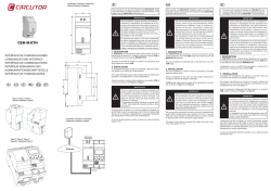
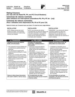
LOAD BREAK SWITCH
GB Instruction sheet
F Notice d'utilisation
E Instrucciones de servicio
AUXILIARY CONTACT
SIRCO M 16 - M 20 - M 25 - M 32 - M 40 - M CD63
SIRCO M 63 - M 80 - M CD100 / SIRCO M 30 - M 60 - M 100 - M 125
Dual dimensions
in/mm
Double dimensions in/mm
Doble dimensiones in/mm
2 NO (F)
Maxi : 2 blocks
1 NO (F) + 1 NC (O) Maxi : 2 CA
IS 533743
22003000
22003002
22003004
22003006
22003009
/
/
/
/
533749I
22003001
22003003
22003005
22003008
UL – CSA products
USED
AUX.
WITH CONTACT
SWITCH
22003000 /22003001
22003002 / 22003003
22003004
22003006 / 22003008
22053000 / 22053001
22053002 / 22053003
22053004
22053006 / 22053008
IS 534924
22013003 / 22013006
22003010 / 22003011
22990001
22990011
(Use only with series SIRCO M)
}
22990001
22990011
O- OFF
IS 533743
Edition 03/12 - IS 533749-I / RECTO-VERSO / S blanc offset quadri 80g/m²
22053000
22053002
22053004
22053006
22053009
/
/
/
/
22053001
22053003
22053005
22053008
*
*
*
*
DISMOUNTING
DEMONTAGE
1
Use copper conductors only, 75°C or higher.
1 x 0,22 mm²
22 -14 AWG
2
2
2 x 2,5 mm²
2x22 - 2x14 AWG
1
0.23 in / 6 mm Stripping distance.
Flat 5,5
pozidriv 1
7.1 lb.in (8.8 lb.in Max)
0.8 Nm (1 Nm Max)
*
3
! PRE-BREAK
: NO PRE-BREAK
NO + NC
Type Za
Same polarity
CONFIGURATION
Maxi : 2 blocks / Maxi : 2 CA
: PRE-BREAK
2 NO
!
If mounted in an enclosure 2214EFGH / 2217EFGH / 2224EFGH / 2227EFGH, see IS 536982
Si monté dans coffrets 2214EFGH / 2217EFGH / 2224EFGH / 2227EFGH, voir IS 536982
Montaje en caja 2214EFGH / 2217EFGH / 2224EFGH / 2227EFGH, ver IS 536982
F= 3, 4 or 5
SIRCO M 16 to M CD63 / SIRCO M 63 to M CD100
E= 3 or 4
H= 0, 1, 2, 3, 4 or 6
G= 0 or 1
SIRCO M 30 - M 60 - M 100 - M 125
Size of end use enclosure : See Instruction Sheet of switches
! DANGER / PELIGRO
H A ZAR DO U S VOLTAG E. This equipment must be installed and serviced only by qualified electrical personnel.Tur n off all power supplying this equipment before working on or inside equipment.
Always use a properly rated voltage sensing device to confirm power is off.Replace all devices, doors, and covers before tur ning on power tothis equipment. Failure to follow these instructions will
result in death or serious injury.
T E N S IO N DAN GER EU S E . L’installation et l’entretien de cet appareil ne doivent être effectués que par du personnel qualifié.Coupez l’alimentation de cet appareil avant d’y travailler.Utilisez toujours
un dispositif de détection de tension à valeur nominale approprié pour confirmer que toute alimentation est coupée.Replacez tous les dispositifs, les portes etles couvercles avant de mettre cet appareil
sous tension. Si ces précautions ne sont pas respectées, cela entraînera la mort ou des blessures graves.
T E N S IO N PEL IG R OS A. Solamente el personal de mantenimiento eléctrico especializado deberá instalar y prestar servicios de mantenimiento a este equipo.Desenergice el equipo antes de realizar
cualqui er trabajo en él.Siempre utilice un dispositivo detector de tensión adecuado para confirmar la desenergización del equipo.Vuelva a colocar todos los dispositivos,las puertas y las cubiertas antes
de energizar este equipo. El incumplimiento de estas precauciones podrá causar la muerte o lesiones serias.
AUXILIARY CONTACT
LOAD BREAK SWITCH
SIRCO MV 100 - MV 125 - MV 160
2 NO (F)
1 NO (F) + 1 NC (O)
Maxi : 2 blocks
Maxi : 2 CA
O- OFF
IS 533745
22003110 / 22004110
22003012 / 22004012
22003016 / 22004016
22990001
22990011
IS 533745
22003110 / 22004110
22003012 / 22004012
22003016 / 22004016
1 x 0,22 mm² / 22 -14 AWG
2 x 2,5 mm² / 2x22 - 2x14 AWG
22990001
22990011
0.23 in / 6 mm
Flat 5,5
pozidriv 1
7.1 lb.in (8.8 lb.in Max) / 0.8 Nm (1 Nm Max)
DISMOUNTING
DEMONTAGE
1
2
2
1
2 NO
3
Size of end use enclosure : See Instruction Sheet of switches
NO + NC
Type Za
Same polarity


© Copyright 2026