
Kinematics of line-plane - digital
2009 IEEE International Conference on Robotics and Automation
Kobe International Conference Center
Kobe, Japan, May 12-17, 2009
Kinematics of Line-Plane Subassemblies in Stewart Platforms
Júlia Borràs and Federico Thomas
Abstract— When the attachments of five legs in a Stewart
platform are collinear on one side and coplanar on the other,
the platform is said to contain a line-plane subassembly. This
paper is devoted to the kinematics analysis of this subassembly
paying particular attention to the problem of moving the
aforementioned attachments without altering the singularity
locus of the platform. It is shown how this is always possible
provided that some cross-ratios between lines —defined by
points in the plane— are kept equal to other cross-ratios
between points in the line. This result leads to two simple
motion rules upon which complex changes in the location of
the attachments can be performed. These rules have interesting
practical consequences as they permit a designer to optimize
aspects of a parallel robot containing the analyzed subassembly,
such as its manipulability in a given region, without altering
its singularity locus.
Index Terms— Parallel manipulators, robot kinematics, architectural singularities, kinematics singularities, manipulator
design.
I. I NTRODUCTION
The kinematic analysis of a Stewart platform gets greatly
simplified when it contains rigid subassemblies. When this
happens the platform forward kinematics can be solved in a
modular fashion and the contribution of each subassembly
to the singularity locus of the platform can be easily singled
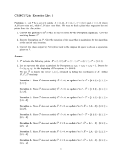
out. There are four basic rigid subassemblies in Stewart
platforms involving linear geometric elements such as points,
lines, and planes (Fig. 1). This paper is devoted to the
kinematics analysis of the line-plane subassembly with the
aim of (a) obtaining a simple characterization of its architectural singularities, and (b) giving simple and complete
rules for modifying the location of the leg attachments in
the subassembly without altering the singularity locus of the
platform.
The number of possibly overlapping subassemblies in
which a Stewart platform can be decomposed was analyzed
by Kong and Gosselin [1]. Gao and col. extended this
analysis to generalized Stewart platforms involving distances
between points, lines and planes instead of only six pairwise
distances between points [2]. Zhang and Song solved, for the
first time, the forward kinematics of general Stewart platform
containing a line-plane subassembly [3]. They showed how
the line in the line-plane subassembly of such a platform can
have up to eight configurations with respect to the plane and,
as a consequence, the platform can have up to 16 assembly
modes. The eight configurations of the line correspond to
The authors are with the Institut de Robòtica i Informàtica Industrial,
CSIC-UPC. Llorens Artigas 4-6, 08028 Barcelona, Spain. E-mails: {jborras,
fthomas}@iri.upc.edu. This work has been partially supported by the
Spanish Ministry of Education and Science, under the I+D project DPI200760858.
978-1-4244-2789-5/09/$25.00 ©2009 IEEE
Fig. 1.
Four rigid subassemblies involving linear geometric elements.
the roots of a bi-quartic polynomial. Therefore, the existence of an algebraic expression for these configurations in
function of the five input distances was proved. Husty and
Karger studied the conditions for this subassembly being
architecturally singular and found two algebraic conditions
that must be simultaneously satisfied [4]. To the best of our
knowledge, no further insights into the analysis of the lineplane subassembly have been presented.
This work can be seen as a continuation of the one
presented in [5], where we studied the line-line subassembly kinematics and where the role of cross-ratios between
attachments in the characterization of architectural singularities, and in the singularity invariant modification of the
attachments locations, was first acknowledged. We show
herein how these ideas can be extended to the line-plane
subassembly.
The paper is organized as follows. The next section
introduces the notation used throughout this paper, and
presents some preliminaries concerning the factorization of
the Jacobian for a platform containing a line-plane subassembly. Section III deals with architectural singularities
and presents a new simple geometric condition, in terms
of cross-ratios, to decide if a given line-plane subassembly
is architecturally singular. Section IV shows how to change
the location of the attachments in a line-plane subassembly
without changing the singularities of the platform. Section
V presents a simple formulation to compute the lengths of
the legs resulting from changing their attachments, using
the transformations presented in the previous section, in
terms of the lengths of the original legs. Section VI shows
how the forward kinematics of a line-plane subassembly
can be fully formulated in terms of distances and solved in
terms of trilaterations. Finally, Section VII summarizes the
contributions of this work.
4094
Authorized licensed use limited to: UNIVERSITAT POLITÈCNICA DE CATALUNYA. Downloaded on December 1, 2009 at 09:44 from IEEE Xplore. Restrictions apply.
II. N OTATION AND PRELIMINARIES
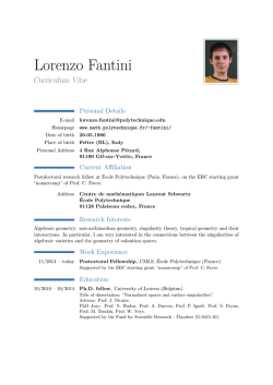
Let us consider the line-plane subassembly contained in
the Stewart platform appearing in Fig. 2. We assume that
no four points in the plane are collinear. Otherwise, this
subassembly would contain a line-line subassembly that
could be studied separately [5]. We also assume that no two
attachments, either in the plane or in the line, are coincident.
b6
PSfrag replacements
b1
i
b2
b3
b4
platform plane, and T is:
wz w(zu − xw) w(zv − yw) z(xw − zu) z(yw − zv)
x2
0
x 2 z2
0
z2
.
z3
x
y
x
y
3
3
3 z3
3 z3
z4
x4
y4
x4 z 4
y4 z4
z5
x5
y5
x5 z 5
y5 z5
(3)
Therefore, the root locus of det(J) can be decomposed
into the root locus due to the line-plane subassembly and that
introduced by the sixth leg. The part of the singularity locus
due to the line-plane subassembly corresponds to the root
locus of the polynomial resulting from expanding det(T),
i.e.,
C1 wz + C2 w(zu − xw) + C3 w(zv − yw)+
C4 z(xw − zu) + C5 z(yw − zv) = 0,
b5
p
(4)
where Ci , for i = 1, . . . 5, is the cofactor of the element i of
the first row of T.
a6
III. A RCHITECTURAL SINGULARITIES
a2
a4
a1
a3
a5
Fig. 2.
Stewart platform containing a line-plane subassembly.
The attachments in the plane have coordinates ai =
(xi , yi , 0), for i = 1, . . . , 5. The pose of the line with
respect to the plane can be described by the position vector
p = (x, y, z) and the unit vector i = (u, v, w) in the direction
of the line. Thus, the coordinates of the attachments in the
line, expressed in the base reference frame, can be written
as bi = p + zi i. Without loss of generality, we can set
x1 = y1 = y2 = z1 = 0 by properly locating the base
reference frame. In order to lighten the notation, an slight
abuse of language is made by using the same symbol to
denote a point and its position vector.
Then, the Plücker coordinates of the five leg lines in the
line-plane subassembly can be written as:
li = (bi − ai , (bi − ai ) × ai )
x + zi u − xi
y + zi v − yi
z + zi w
,
=
−yi (z + zi w)
xi (z + zi w)
yi (x + zi u − xi ) − xi (y + zi v − yi )
(1)
and that of the sixth leg, simply as l6 = (v, m)T .
The singularity locus of the platform is defined as the root
locus of det(J) [6], where J is the matrix J = (l1 , . . . , l6 ).
It can be checked that this determinant factors as follows:
det(J) = det(T)K(a6 , b6 ),
(2)
where K(a6 , b6 ) is zero if, and only if, a6 lies on the
In the particular case in which det(T) is identically zero,
independently of the pose of the line with respect to the
plane, the subassembly is said to be architecturally singular
[7]. Next, we concentrate ourselves in the characterization
of this kind of singularities.
Note that det(T) is zero —independently of the pose of
the line— if, and only if, all the coefficients in equation (4)
are zero. Since such coefficients are the cofactors of elements
of the first row of T, we can say that det(T) is identically
zero if, and only if, the submatrix formed by the last four
rows of T, say T̂, is rank defective. This circumstance can
be easily detected by applying Gaussian elimination on T̂.
After performing standard Gaussian elimination on T̂, the
last row of the resulting matrix is:
1
0 0 0 −C4 C5
(5)
D
where Ci are the same cofactors appearing in (4), and
z2 x 2 0 (6)
D = z3 x3 y3 .
z4 x 4 y 4 Thus, if C4 = C5 = 0, the line-plane subassembly will be
architecturally singularity. It can be shown that, by permuting
the indices of the attachment, we can always find a value for
D different from zero.
It can be checked that the conditions C4 = 0 and C5 =
0 are one-to-one equivalent to the two algebraic conditions
presented in [4, Theorem 1.6].
If we would perform Gaussian elimination on the vertically mirrored version of T̂, the last row in the resulting
matrix would be:
1
0 0 0 −C1 C2 .
(7)
z2 x2 y3 y4 (z3 − z4 )
Thus, we can alternatively say that a line-plane subassembly
is architecturally singular if, and only if, C1 = C2 = 0.
Actually, by permuting the columns of T̂, we can conclude
4095
Authorized licensed use limited to: UNIVERSITAT POLITÈCNICA DE CATALUNYA. Downloaded on December 1, 2009 at 09:44 from IEEE Xplore. Restrictions apply.
that a line-plane subassembly is architecturally singular if,
and only if, any two cofactors are zero. In any case, to avoid
an undefined quotient, the denominator resulting from the
applied Gaussian elimination must be different from zero,
which is always possible by permuting the indices of the
attachments.
It has been proved that a line-line subassembly is architecturally singular if, and only if, the cross-ratios between the
attachments in both lines are equal [5]. It is interesting to
see how the condition C1 = C2 = 0 can also be interpreted
geometrically in terms of cross-ratios.
Given four collinear points with coordinates pi =
(ni , 0, 0), for i = 1, . . . 4, their cross-ratio is defined as:
CR(p1 , p2 , p3 , p4 ) =
(n3 − n1 )(n4 − n2 )
.
(n4 − n1 )(n3 − n2 )
(8)
g replacements
Likewise, for a set of four coplanar and concurrent lines,
l1 , l2 , l3 , l4 , their cross-ratio CRl (l1 , l2 , l3 , l4 ) is defined as
the cross-ratio of the four points resulting from intersecting
these four lines with an arbitrary line, in general position,
lying in the same plane [8, Section IV.3].
the coefficients a, b, c, e, and f are uniquely determined.
Actually, (9) can be expressed in terms of these five points
as:
z x y
xz
yz 1
z1 x 1 y 1 x 1 z1 y 1 z1 1 z2 x 2 y 2 x 2 z2 y 2 z2 1 z3 x3 y3 x3 z3 y3 z3 1 = 0.
z4 x 4 y 4 x 4 z4 y 4 z4 1 z5 x 5 y 5 x 5 z5 y 5 z5 1 Observe that, if we substitute one of the chosen five points
by any other point in the hypersurface, the resulting equation
will have the same coefficients up to a scalar multiple.
Since in our case x1 = y1 = z1 = y2 = 0, the above
equation yields
z x y
xz
yz z2 x 2 0 x 2 z2
0 z3 x3 y3 x3 z3 y3 z3 = 0.
(10)
z4 x 4 y 4 x 4 z4 y 4 z4 z5 x 5 y 5 x 5 z5 y 5 z5 In other words,
C1 z + C2 x + C3 y + C4 zx + C5 zy = 0
b1
b2
b3
r1
a3
b4
r3
s3
s5
r5
a1
a2
s2
(11)
where Ci are the cofactors referred in the previous section,
i.e.,
the same coefficients appearing in (4).
b5
Now, if we change the attachments of one leg so that
the coordinates of the new attachments satisfy (10), the
coefficients of the singularity polynomial in (4) remain the
same up to a constant multiple and, as a consequence, its root
locus remains invariant. This simple observation gives us the
PSfrag replacements
clue to change the attachments in a line-plane subassembly
a5
without changing the platform singularity locus.
a4
b1
r4
b2
b3
s4
b5
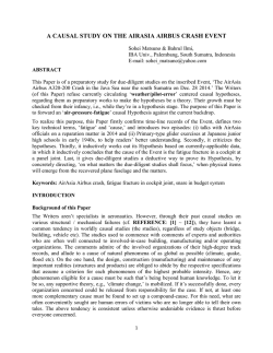
Fig. 3. A line-plane subassembly is architecturally singular if, and only if,
CR(b2 , b3 , b4 , b5 ) = CRl (s2 , s3 , s4 , s5 ) and CR(b1 , b3 , b4 , b5 ) =
CRl (r1 , r3 , r4 , r5 ). By permuting indices, up to ten equivalent sets of
conditions can be derived.
B
B z1
B z5
a1
B z3
a3
a4
B z4
a5
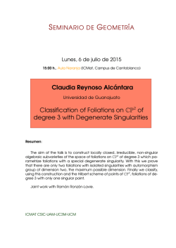
Fig. 4. The one-to-one correspondence between the attachments in the line
and the lines of the pencil centered at B. Each value of zi defines a point
in the line, bi = p + zi i, and a line in the plane Bzi .
SINGULARITIES
Let us consider the multilinear equation
ax + by + cz + dxz + eyz + f = 0,
B z2
a2
A line-plane subassembly is architecturally singular if,
and only if, CR(b2 , b3 , b4 , b5 ) = CRl (s2 , s3 , s4 , s5 ) and
CR(b1 , b3 , b4 , b5 ) = CRl (r1 , r3 , r4 , r5 ) (Fig.3). By permuting indices, up to ten equivalent sets of conditions can
be derived. It can be proved that all of them are equivalent
to the corresponding cofactor conditions Ci = Cj = 0 for
i, j ∈ {1, ..., 5}, i 6= j (in Fig.3, C1 = C2 = 0).
IV. C HANGING ATTACHMENTS WITHOUT CHANGING
b4
(9)
which implicitly defines a hypersurface in the space defined
by (x, y, z) ∈ R3 . The attachments of leg i of our line-plane
subassembly define a point, (xi , yi , zi ), in this hypersurface.
Since we have five legs (i.e., five points in this hypersurface),
Equation (10) implicitly defines a one-to-one correspondence between points in the line and lines in the plane.
Indeed, given an attachment in the plane with coordinates
(x, y, 0), we conclude from equation (10) that there is a
unique corresponding attachment in the line with coordinate
z. On the way round, given an attachment in the line, a line
4096
Authorized licensed use limited to: UNIVERSITAT POLITÈCNICA DE CATALUNYA. Downloaded on December 1, 2009 at 09:44 from IEEE Xplore. Restrictions apply.
b1
b2
ai
b3
b1
b2
ai
b3 b0
i
b4
a1
a3
b0i
Bz
ai
i
i
B
a2
a1
a4
b3 b0
b4
bi
B
a0i
b2
b4
bi
a2
b1
a3
a0i
B 0
z
i
B
a2
bi
a1
a3
a0i
a4
Bz
Bz
i
B 0
z
i
a4
i
B 0
z
i
(a)
Fig. 5.
(b)
(c)
It is possible to move an attachment in the plane to any arbitrary location by following three steps (see text for details).
is defined in the plane through equation (10). It is important
to realize that, as z varies, a pencil of lines is generated
in
PSfrag replacements
the plane. In other words, the generated lines intersect at a
single point whose coordinates are:
−C2 C1
C3 C1
,
,0 .
(12)
C2 C5 − C 4 C3 C2 C5 − C 4 C3
b1
b2
b4
b5
b3
In what follows, the point with the above coordinates will
a3
a1
a2
be called the center of the correspondence. It will be denoted
by B and any line in the plane passing through it will be
a5
a4
called a B-line (Fig. 4).
Finally, two simple rules to move the attachments without
altering the singularity locus naturally arise:
(a)
• all attachments in the plane can be freely moved along
b1
b2
their B-lines, and
b4
b5
• an attachment in the line can be freely moved if, and
b3
PSfrag replacements
only if, the other attachment of the corresponding leg
is located at B.
Following these two rules, it is possible to move any
a4
attachment in the plane, say ai , to any arbitrary location,
a5
0
say ai , in three steps (Fig. 5):
• move ai along the corresponding B-line until it meets
a3
a1
a2
B,
• move bi till its coordinate in the line determines a Bline that contains a0i , and
0
• move ai along the B-line that contains ai .
Thus, it is possible to carry out many complex transfor(b)
mations, but special attention must be paid to avoid that, at
Fig. 6. Given a general line-plane subassembly, what is the maximum
each step,
number of attachments that, following the proposed transformations, can be
• no three attachments in the plane are located in the
made coincident?
same B-line because three leg lengths would become
dependent, and
• no four attachments in the plane are collinear as, in
motion rules, can be made coincident? Two attachments in
this case, the line-plane subassembly would contain the plane can be readily made coincide by taking them along
an architecturally singular line-line subassembly. This their B-lines till they meet at B [Fig. 6(a)]. Afterwards,
rather surprising result will become evident at the end their corresponding attachments in the line can be moved
of this section where the proposed transformations are to coincide with two other attachments [Fig. 6(b)]. Note
interpreted in terms of cross-ratios.
that no further coincidences are possible without incurring in
Given a general line-plane subassembly, what is the one of the two previous exceptions. It is obvious that other
maximum number of attachments that, following the above valid line-plane subassemblies including more coincident
r
4097
Authorized licensed use limited to: UNIVERSITAT POLITÈCNICA DE CATALUNYA. Downloaded on December 1, 2009 at 09:44 from IEEE Xplore. Restrictions apply.
attachments exist, but we can ensure that their singularity
loci will be essentially different from that of the general
line-plane subassembly.
Finally, it is worth noting that a one-to-one correspondence
between lines and/or points exists through a multilinear
expression if, and only if, the cross-ratio of any set of
four lines in a plane or four points in a line is equal to
the cross-ratio of their correspondents. This fact derives
from [9, Theorem II.2]. Since (10) defines a one-to-one
correspondence through a multilinear function between lines
and points, we can conclude that the cross-ratio of any four
B-lines must be equal to the cross-ratio of the corresponding
attachments in the line. This provides and alternative way
for computing B and, what is much more important, an
alternative way of defining all valid changes in the location of
the attachments as those that keep invariant the cross-ratios
between the B-lines in the plane and their corresponding
attachments in the line.
can always find a non-singular linear system by choosing
the right parameter.
Solving the above system for d2 using the Cramer’s rule,
we get
x 2 0 x 2 z2
0
z2 t + N2 x 3 y 3 x 3 z3 y 3 z3 z3 t + N 3 x 4 y 4 x 4 z4 y 4 z4 z4 t + N 4 x 5 y 5 x 5 z5 y 5 z5 z5 t + N 5 x y
xz
yz
zt + N 2
.
(15)
d =
1
2 C1
In other words,
where
V. C OMPUTING LEG LENGTHS
This section shows how to compute the length of the legs
resulting from changing the location of their attachments,
using the motion rules presented in the previous section, in
terms of the lengths of the original legs.
The leg lengths of our line-plane subassembly can be
expressed as li2 = kbi − ai k, for i = 1, . . . , 5. Then, if
we subtract from the expression for li , i = 2, . . . , 5, the
equations u2 + v 2 + w2 = 1 and l12 = x2 + y 2 + z 2 , quadratic
terms cancel yielding
zi t−xi x − yi y − xi zi u − yi zi v
+ 1/2(x2i + yi2 + zi2 + l12 − li2 ) = 0,
(13)
for i = 2, . . . , 5, where t = −p · i, x, y, u and v are
unknowns.
Now, suppose we want to compute the distance d2 = kb−
ak between the point in the plane a = (x, y, 0) and the point
in the line b = p + zi, where {x, y, z} satisfies equation
(10). If we subtract from the expression for d2 the equations
u2 + v 2 + w2 = 1 and l12 = x2 + y 2 + z 2 , quadratic terms
cancel, as above. The resulting expression for d2 , together
with the equations in (13), lead to a system of five equations
in six unknowns. If we take t as parameter, the resulting
linear system can be written as:
x 2 0 x 2 z2
0
0
z2 t + N 2
x
x3 y3 x3 z3 y3 z3 0 y z3 t + N3
x4 y4 x4 z4 y4 z4 0 u = z4 t + N4 ,
x5 y5 x5 z5 y5 z5 0 v z5 t + N5
1
zt + N
d2
x y
xz
yz
2
(14)
where Ni = 21 (x2i + yi2 + zi2 + l12 − li2 ) and N = 12 (x2 +
y 2 + z 2 + l12 ). The determinant of this linear system is 12 C1 ,
that is, the cofactor of the first element of T̂. If this cofactor
is zero, we can always choose as parameter either x, y, u,
or v, to reformulate the above linear system. Since for a
non-architecturally singular line-plane subassembly no two
cofactors are zero (as we have proved in Section III), we
and
x 2
x 3
r = x4
x 5
x
x 2
x 3
s = x4
x 5
x
d2 =
rt + s
,
1
2 C1
0
y3
y4
y5
y
x 2 z2
x 3 z3
x 4 z4
x 5 z5
xz
0
y3
y4
y5
y
x 2 z2
x 3 z3
x 4 z4
x 5 z5
xz
0
y 3 z3
y 4 z4
y 5 z5
yz
0
y 3 z3
y 4 z4
y 5 z5
yz
(16)
z2 z3 z4 z5 z
N2 N3 N4 .
N5 N
(17)
(18)
Finally, notice that, for any set of values for x, y, and
z satisfying (10), r = 0. Therefore, the length of any
leg, resulting from the changes in its attachments following
the rules proposed in the previous section, can be readily
computed as the quotient of two determinants involving
the attachment coordinates and the leg lengths prior to the
changes.
VI. F ORWARD KINEMATICS
Given the general line-plane subassembly in Fig.7, the
lengths of the dotted segments in blue, l1 , l3 , and l4 , can
be obtained using the formula presented in the previous
section. Then, the lengths of the dotted segments in red u1 ,
u2 , u3 and u4 , can be obtained using standard techniques
from Distance Geometry, as described below. Once these
distances are known, the forward kinematics of our lineplane subassembly can trivially solved by a sequence of
trilaterations [10].
The Cayley-Menger determinant, D(p1 , ..., pn ) of the set
of points p1 , ..., pn is defined as the determinant of the (n +
1) × (n + 1) matrix with the last row and column entries set
to one and its ij entry, the square distance between pi and
pj [10]. This determinant is proportional to squared volume
of the (n − 1)-dimensional simplex defined by the n points.
Thus, in three dimensions, the Cayley-Menger determinant of
five or more points is necessarily zero. Then, we can establish
the following quadratic relation between u21 and u22 .
D(a2 , b2 , B, b5 , a5 ) =
2 X
2
X
pij (u21 )i (u22 )j = 0
i=0 j=0
4098
Authorized licensed use limited to: UNIVERSITAT POLITÈCNICA DE CATALUNYA. Downloaded on December 1, 2009 at 09:44 from IEEE Xplore. Restrictions apply.
(19)
b2
b3
b1
b4
u4
b5
u1
u3
u2
l1
l5
l4
l3
l2
B
a01
a1
a5
a2
a3
a4
Fig. 7. The forward kinematics of a line-plane subassembly can be fully formulated in terms of distances. l 1 , l3 and l4 can be computed using the
distance formula presented in Section V. Then, ui , for i = 1, . . . , 4 can be obtained using standard Distance Geometry techniques.
Since the Cayley-Menger determinant of four coplanar points
must also be zero, because the volume of the simplex
defined by the four points is degenerate, the following linear
equations in u2i , i = 1, . . . , 4 can also be readily obtained:
D(b1 , b2 ,b5 , a2 ) = s12 u22 + s25 u23 +
(s12 + s25 )l22 + s12 s25 (s12 + s25 ) = 0
D(b1 , b2 ,b5 , a5 ) = s12 l52 + s25 u24 +
(s12 + s25 )u21 + s12 s25 (s12 + s25 ) = 0
D(a01 , a2 ,a5 , b1 ) = r12 u24 + r25 l12 +
(r12 + r25 )u23 + r12 r25 (r12 + r25 ) = 0,
(20)
(21)
(22)
architectural singularities and singularity-invariant transformations in terms of cross-ratios has given us much insight
into both problems, mainly because of its straightforward
geometric and visual interpretation. We actually conjecture
that this characterization can be extended to general Stewart
platforms.
Finally, it is worth noting that locating a line, with respect
to a plane, from a set of pairwise distances between points
in the line and in the plane is a basic operation that arises in
constraint-based geometric modeling. As a consequence, it
is worth investigating the repercussions the presented results
to this problem.
where rij are distances between base points ai and aj and
sij distances between line points bi and bj .
Using (20) and (21), we obtain values for u23 and u24 that
can be substituted in (22), thus obtaining a linear equation
in squared distances of the form:
ACKNOWLEDGEMENT
The authors would like to thank Carme Torras and
Maria Alberich-Carramiñana for their technical comments
and helpful advice during the development of this work.
(23)
[1] X. Kong and C.M. Gosselin, “Classification of 6-SPS Parallel Manipulators According to Their Components,” Proc. ASME Des. Eng. Tech.
Conf., 2000.
[2] X. Gao, D. Lei, Q. Liao, and G-F. Zhang, “Generalized Stewart-Gough
platforms and their direct kinematics,” IEEE Trans. on Robotics, Vol.
21, No. 2, pp. 141-151, 2005.
[3] C. Zhang and S.M. Song, “Forward Kinematics of a Class of Parallel
(Stewart) Platforms with Closed-Form Solutions,” Proc. IEEE Intl.
Conf. on Robotics and Automation, pp. 2676-2681, 1991.
[4] M.L. Husty and A. Karger, “Architecture Singular Parallel Manipulators
and Their Self-Motions,” Advances in Robot Kinematics, J. Lenarcic
and M. M. Stanisic (eds.), Kluwer Academic Publishers, pp. 355-364,
2000.
[5] J. Borràs, F. Thomas, and C. Torras, “Architecture singularities in
flagged parallel manipulators,” Proc. of the IEEE Intl. Conf. on Robotics
and Automation, pp. 3844-3850, 2008.
[6] J.-P. Merlet, Parallel Robots, Springer, 2000.
[7] O. Ma and J. Angeles, “Architecture Singularities of Platform Manipulators,” Proc. IEEE Intl. Conf. on Robotics and Automation, Vol. 2, pp.
1542-1547, 1991.
[8] R. Courant and H. Robbins, What is Mathematics? Oxford Univesity
Press, 1996.
[9] E.A. Maxwell, The Methods of Plane Projective Geometry based on
the use of General Homogeneous Coordinates, Cambridge University
Press, 1960.
[10] J.M. Porta, L. Ros, and F. Thomas, “On the Trilaterable Six-Degreeof-Freedom Parallel and Serial Manipulators,” Proc. of the IEEE Int.
Conf. on Robotics and Automation, pp. 960 - 967, 2005.
p1 u21
+
p2 u22
+ p3 = 0.
Finally, using (19) and (23), we obtain a resultant polynomial
of degree four in u21 . Then, a closed-form solution for u21
exists. For each possible value for u21 , four possible poses
for the line with respect to the plane can be found by
trilateration. Using the corresponding values for u22 , u23 and
u24 to discriminate solutions, only two possible poses for each
value of u21 are possible. Actually, they are mirror solutions
with respect to the plane. Thus, a line-plane subassembly can
attain up to eight assembly modes, a result consistent with
that presented by Zhang and Song in [3].
VII. C ONCLUSIONS
A kinematics analysis of the line-plane subassembly with
especial emphasis on singularity-invariant transformations in
the locations of its leg attachments has been presented. It has
been shown how these transformations can be interpreted as
those that keep invariant some cross-ratios between points in
the line and lines in the plane, and how similar cross-ratios
also permit to decide if the given line-plane subassembly is
architecturally singular. This remarkable characterization of
R EFERENCES
4099
Authorized licensed use limited to: UNIVERSITAT POLITÈCNICA DE CATALUNYA. Downloaded on December 1, 2009 at 09:44 from IEEE Xplore. Restrictions apply.


© Copyright 2026