
Trasmettitore
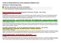
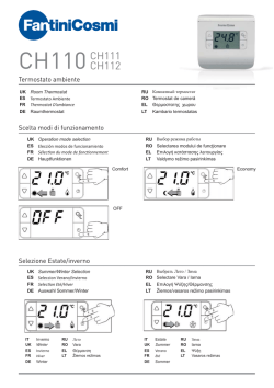
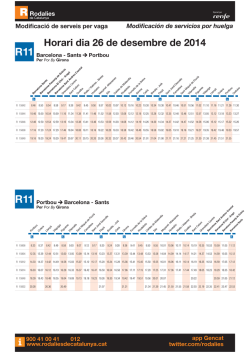
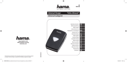
DBCT Ingombri e misure fori Trasmettitore TRASMETTTORE CORDLESS I MANUALE D’INSTALLAZIONE L’INSTALLAZIONE” “ISTRUZIONI IMPORTANTI PER LA SICUREZZA DURANTE ATTENZIONE: L’INSTALLAZIONE NON CORRETTA PUÒ CAUSARE GRAVI DANNI SEGUIRE TUTTE LE ISTRUZIONI DI INSTALLAZIONE IL PRESENTE MANUALE È DESTINATO SOLAMENTE A INSTALLATORI PROFESSIONALI O A PERSONE COMPETENTI. Legenda simboli Questo simbolo segnala parti da leggere con attenzione. Questo simbolo segnala parti riguardanti la sicurezza. Installazione Prima di procedere all’installazione è necessario: • Assicurarsi che la tensione di linea sia scollegata. Riferimenti normativi • Verificare che il punto di fissaggio dell’apparecchiatra Per il prodotto in oggetto sono state considerate le seguenti sia in una zona protetta dagli urti, che le superfici di ancoragnormative di riferimento: EN 12978, UNI EN 954-1, CEI EN 60335-1, gio siano solide, e che il fissaggio venga fatto con elementi idonei (viti, tasselli, ecc) alla superficie. UNI EN 12453. • Predisporre tubazioni e canaline adeguate per il passaggio dei Descrizione dispositivo cavi elettrici garantendone la protezione contro il danneggiamento meccanico. Dispositivo di protezione ad infrarossi composto da: Questo simbolo segnala le note da comunicaall’utente. - 05 06 07 08 09 V1 V2 V3 AAA R22 + 1,5V AAA 1,5V R13 R15 K 2 - + - + + K K Alimentazione: 6 V (4 batterie da 1.5V AAA) 1 + - + 1 2 3 4 5 6 7 8 9 10 11 12 + AAA 1,5V 05 06 07 08 09 V1 V2 V3 AAA 1-Alloggiamento batterie 2-Dip di selezione led di trasmissione 3-Morsettiera di collegamento bordo sensibile di sicurezza (se usata con serie DBS bisogna togliere il ponte sulla morsettiera.) - + - R23 + - + - Trasmettitore 1,5V Caratteristiche tecniche Trasmettitore Descrizione/Collegamenti elettrici e funzioni DIP 1 2 3 4 5 6 7 8 9 10 11 12 - Trasmettitore alimentato da 4 batterie con DIP per selezione funzioni. Progettato e costruito interamente dalla CAME Cancelli Automatici S.p.A. Garantito 24 mesi salvo manomissioni. - Grado di protezione IP 54. - Trasmettitore cordless per automatismi serie DBS CAME -Distanza massima Trasmettitore /Ricevitore 10 m Materiali: Corpo principale PC-ABS UL94V0, inserti in policarbonato Temperatura : n°1 n°2 K K K R22 R15 Grado di protezione: IP54 R13 R23 Assorbimento: 70 µA 3 n°3 # # ON 1 2 3 4 Funzione Dip Dip 1 in ON = Attivo foto diodo n°1 Dip 2 in ON = Attivo foto diodo n°2 Dip 3 in ON = Attivo foto diodo n°3 Dip 4 in ON = Deve essere in ON R15 + AAA 1,5V R15 R22 6!!! + - 05 06 07 08 09 V1 V2 V3 - + - AAA 1,5V 1 2 3 4 5 6 7 8 9 10 11 12 6!!! R22 - R23 + 05 06 07 08 09 V1 V2 V3 1 2 3 4 5 6 7 8 9 10 11 12 + - + R23 AAA R13 4 - 3 R22 AAA 05 06 07 08 09 V1 V V2 V3 1,5V 1,5V 6!!! + R15 1 2 3 4 5 6 7 8 9 10 11 12 6!!! + R13 R23 K 2 6!!! 6!!! 6!!! K K K K 1 6!!! Trasmettitore lato dx del motore dip 1 in ON e Ricevitore con Dip 1 in ON • Una volta collegato al bordo sensibile, selezionare il fotodiodo (vedere esempio qui a lato e pagina precedente) e procedere con l’inserimento delle batterie (n° 4 da 1.5V AAA) rispettando la polarità riportata sulla scheda. R13 Esempio applicativo serie DBS 02. K • Chiudere il dispositivo agganciando dall’alto il coperchio e fissandolo con le viti in dotazione. K K K C NC 24V 0 TS 643#.# 1 2 1 2 3 4 Demolizione e smaltimento Trasmettitore lato sx del motore dip 3 in ON e Ricevitore con Dip 2 in ON Installazione Trasmettitore Consultare la documentazione di DBS01/02 per il posizionamento e il collegamento al bordo sensibile, quindi: • Procedere con il fissaggio del fondo del trasmettitore, utilizzando le viti UNI 6954 3.9x32 in dotazione. Smaltimento: prodotto e imballi sono costituiti da diverse tipologie di materiali, la maggior parte dei quali (carta, plastica etc.) assimilabili a rifiuti solidi urbani e quindi riciclabili attraverso la raccolta differenziata. Batterie ed eventuali altri materiali contenenti sostanze pericolose vanno invece rimossi e affidati a ditte abilitate al recupero e smaltimento degli stessi. Verificare sempre le normative specifiche vigenti nel luogo di smaltimento. NON DISPERDERE NELL’AMBIENTE! Dichiarazione del fabbricante Dichiarazione di conformità la CAME Cancelli Automatici S.p.A. via Martiri della Libertà, 15 31030 Dosson di Casier - Treviso - ITALY TEL(+39) 0422 4940 - fax (+39) 0422 4941 internet: www.came.it - e-mail: [email protected] Dichiarano sotto la propria responsabilità, che i seguenti prodotti per l’automazione di cancelli e porte da garage, cosi denominati: DBCT Sono conformi ai requisiti essenziali ed alle disposizioni pertinenti, stabilite dalle seguenti Direttive e alle parti applicabili delle normative di riferimento in seguito elencate: Direttiva Compatibilità Elettromagnetica 2004/108/CE Direttiva Bassa Tensione 2006/95/CE Direttiva Macchine 98/37/CE EN 61000-6-1 EN 61000-6-2 EN 61000-6-3 EN 60335-1 EN 13241-1 L’amministratore delegato Sig. Gianni Michielan 119RU83 ver 0.1 - 09/2008 DBCT Dimensions and Hole Measurements Transmitter CORDLESS TRANSMITTER GB “IMPORTANT INSTRUCTIONS FOR SAFE INSTALLATION” WARNING: IMPROPER INSTALLATION MAY CAUSE SERIOUS DAMAGE. FOLLOW ALL INSTALLATION INSTRUCTIONS. THIS MANUAL IS INTENDED ONLY FOR PROFESSIONAL INSTALLERS OR QUALIFIED PERSONNEL. INSTALLATION MANUAL Legend This symbol refers to sections to be read carefully. Installation Before proceeding with the installation, it is necessary to: • make sure that the mains power is off. T his symbol refers to notes to be communicated to users. • Check that the product is installed in an area protected from bumps and that the anchorage surface is solid, and that it is Reference to Regulations secured with suitable elements (screws, inserts, etc). The following standards have been complied with for the product: EN • Install suitable tubes and ducts for electric cable passage to 12978, UNI EN 954-1, CEI EN 60335-1, UNI EN 12453. guarantee protection against mechanical damage This symbol refers to sections concerning safety. Device Description + - AAA R15 - 1,5V + 05 06 07 08 09 V1 V2 V3 + AAA 1,5V R13 1 2 3 4 5 6 7 8 9 10 11 12 AAA 05 06 07 08 09 V1 V2 V3 R22 K 2 - + - + 1 + K K Technical Characteristics - + - + + - 1,5V - Cordless transmitter for DBS CAME series automation systems - Maximum distance transmitter/receiver: 10 m AAA - Degree of protection: IP 54. 1,5V Guaranteed 24 months if not tampered with. 1- Battery lodging 2-Transmission LED indicator selection dip-switch 3-Connection terminal board for safety sensitive edges (the bridge on the terminal board must be removed if used with the DBS series.) 1 2 3 4 5 6 7 8 9 10 11 12 Wholly designed and built by CAME Cancelli Automatici S.p.A. + - function selection. Transmitter R23 - Battery-powered (four batteries) transmitter with dip-switches for - Description/Electric Connections and Dip-Switch Functions Infrared protection device composed of: n°1 Absorption: 70 µA n°2 K K K R22 R15 Power: 6 V (four 1.5V AAA batteries) R13 R23 Transmitter Dip-switch functions Dip 1 ON = photo diode 1 is active Dip 2 ON = photo diode 2 is active Dip 3 ON = photo diode 3 is active Dip 4 ON = must be set to ON Degree of protection: IP54 Material: PC-ABS UL94V0 / Polycarbonate / TPA1 65 NT Marpram mar # Working temperature: # 3 n°3 ON 1 2 3 4 R15 + AAA 1,5V R15 R22 6!!! 05 06 07 08 09 V1 V2 V3 - + - + - AAA 1,5V 1 2 3 4 5 6 7 8 9 10 11 12 6!!! R22 - R23 + 05 06 07 08 09 V1 V2 V3 1 2 3 4 5 6 7 8 9 10 11 12 + - + R23 AAA R13 4 - 3 R22 AAA 05 06 07 08 09 V1 V V2 V3 1,5V 1,5V 6!!! + R15 1 2 3 4 5 6 7 8 9 10 11 12 6!!! + R13 R23 K 2 6!!! 6!!! 6!!! K K K K 1 6!!! Transmitter right side of motor dip-switch 1 set at ON and Receiver with dip-switch 1 set at ON • Once it has been connected to the sensitive edge, select the photodiode (see the example alongside and on the previous page) and install the batteries (4 x 1.5V AAA) checking the polarity on the board. R13 Example for DBS 02 Series K • Close the device, hooking the cover on from the top and use the supplied screws to secure it in place. K K K C NC 24V 0 TS 643#.# 1 2 1 2 3 4 Demolition and Disposal Transmitter left side of motor dip-switch 3 set at ON and Receiver with dipswitch 2 set at ON PRODUCT DISPOSAL – Our products and packaging are made up of various types of materials. Most of them (paper, plastics, etc.) may be disposed of in normal garbage collection bins and can be recycled by disposing of in specific recyclable material collection bins and disposal in authorized centres. Batteries and any other materials containing hazardous substances, however, should be removed and given to qualified service companies for proper disposal. Prior to disposal, it is always advisable to check specific regulations in force in the place of disposal. PLEASE DISPOSE OF PROPERLY! Transmitter Installation Refer to the DBS01/02 instructions for the position and connection to the sensitive edge and then: • Secure the base of the transmitter UNI6954 3.9x32 screws . , using the supplied Manufacturer’s declaration Declaration of conformity la CAME Cancelli Automatici S.p.A. via Martiri della Libertà, 15 31030 Dosson di Casier - Treviso - ITALY internet: www.came.it - e-mail: [email protected] Declare under their own responsibility that the following products for gate and garage door automation called: DBCT Are compliant with essential requirements and with pertinent regulations established by the following directives and to the applicable parts of the standards listed below: Electromagnetic compatibility directive 2004/108/CE Electrical equipment designed for use within certain voltage limits directive 2006/95/CE Machinery directive 98/37/EC EN 61000-6-1 EN 61000-6-2 EN 61000-6-3 EN 60335-1 EN 13241-1 L’amministratore delegato Sig. Gianni Michielan 119RU83 ver 0.1 - 09/2008 DBCT Dimensions d’encombrement et distance entre les trous Émetteur ÉMETTEUR SANS FIL FR NOTICE DE MONTAGE “INSTRUCTIONS IMPORTANTES POUR LA SÉCURITÉ LORS DU MONTAGE” ATTENTION : UN MAUVAIS MONTAGE PEUT PROVOQUER DE GRAVES DEGATS, SUIVRE TOUTES LES INSTRUCTIONS RELATIVES AU MONTAGE CETTE NOTICE N’EST DESTINÉE QU’AUX INSTALLATEURS PROFESSIONNELS OU À DU PERSONNEL COMPÉTENT Légende des symboles Ce symbole signale les parties à lire attentivement. Montage Ce symbole signale les parties concernant la sécurité. Avant de procéder au montage, il faut : • S’assurer que le courant est coupé. • Vérifier si le point de fixation de l’appareil est à l’abri des chocs, Références aux normes si les surfaces d’ancrage sont solides et si l’appareil est fixé avec Les normes de référence suivantes ont été considérées pour des éléments appropriés (vis, chevilles, etc.) à la surface. l’appareil en objet : EN 12978, UNI EN 954-1, CEI EN 60335-1 et • Prévoir des tuyaux et des canalisations appropriés pour faire UNI EN 12453. passer les câbles électriques, en en garantissant la protection contre tout dommage mécanique C e symbole signale les notes à communiquer à l’utilisateur. Description du dispositif - 05 06 07 08 09 V1 V2 V3 AAA + 1,5V R22 R15 K 2 - + - + + K K Caractéristiques techniques 1 + - + AAA 1,5V R13 1 2 3 4 5 6 7 8 9 10 11 12 AAA 1,5V 05 06 07 08 09 V1 V2 V3 AAA 1,5V 1 2 3 4 5 6 7 8 9 10 11 12 1-Logement des piles Conçu et fabriqué entièrement par CAME Cancelli Automatici S.p.A. 2-Commutateur de sélection du led de transmission Garanti 24 mois sauf en cas d’altération 3-Bornier de branchement bord - degré de protection IP 54. sensible de sécurité (il faut enlever le fil de connexion - Émetteur sans fil pour automatismes de la série DBS CAME sur le bornier s’il est utilisé - Distance maximale Émetteur/ Récepteur 10 m avec la série DBS). - + - + + - - sélectionner les fonctions. Émetteur R23 - Émetteur alimenté par 4 piles avec des commutateurs pour - Description/ Branchements électriques et fonction des commutateurs + Dispositif de protection à infrarouges comprenant : Absorption : 70 µA n°2 K K K R22 R13 n°1 R15 Alimentation : 6 V (4 piles de 1.5V AAA) R23 Émetteur Degré de protection : IP54 Matériau : PC-ABS UL94V0 / Polycarbonate / Marpram mar TPA1 65 NT # Température : # ON 1 2 3 3 n°3 4 Fonction des commutateurs Comm. 1 ON = Active la photodiode n° 1 Comm. 2 ON = Active la photodiode n° 2 Comm. 3 ON = Active la photodiode n° 3 Comm. 4 ON = il doit être sur ON R15 + AAA 1,5V R15 R22 6!!! 05 06 07 08 09 V1 V2 V3 - + - + - AAA 1,5V 1 2 3 4 5 6 7 8 9 10 11 12 6!!! R22 - R23 + 05 06 07 08 09 V1 V2 V3 1 2 3 4 5 6 7 8 9 10 11 12 + - + R23 AAA R13 4 - 3 K • Fermez le dispositif en attachant le couvercle en haut en le fixant avec les vis en dotation. et R22 AAA 05 06 07 08 09 V1 V V2 V3 1,5V 1,5V 6!!! + R15 1 2 3 4 5 6 7 8 9 10 11 12 6!!! + R13 R23 K 2 6!!! 6!!! 6!!! K K K K 1 6!!! Émetteur côté droit du moteur commutateur 1 sur ON et Récepteur avec commutateur 1 sur ON • Lorsque vous serez raccordé au bord sensible, sélectionnez le photodiode (voir exemple ci-contre et page précédente) et procédez avec l’introduction des batteries (4 batteries de 1,5V AAA) en respectant la polarité indiquée sur la carte. R13 Exemple d’application série DBS 02 K K K C NC 24V 0 TS 643#.# 1 2 1 2 3 Démolition et élimination 4 Élimination : l’appareil et l’emballage sont constitués de plusieurs types de matériaux dont la plupart (papier, plastique, etc.) peuvent être considérés comme des déchets solides urbains et donc recyclés après les avoir triés. Il faut par contre enlever les piles ou tout autre élément du même genre contenant des substances dangereuses et les confier à des sociétés chargées de les récupérer ou de les éliminer. Toujours se conformer à la réglementation spécifique en vigueur dans le pays où l’appareil a été utilisé. NE PAS LE JETER N’IMPORTE OÙ ! Émetteur côté gauche du moteur commutateur 3 sur ON et Récepteur avec Commutateur 2 sur ON Montage de l’émetteur Consultez la documentation de DBS01/02 pour le positionnement et le raccordement au bord sensible, donc : • Procédez avec la fixation du fond de l’émetteur utilisant les vis UNI 6954 3.9x32 en dotation. , en Déclaration du fabricant Déclaration de conformité la CAME Cancelli Automatici S.p.A. via Martiri della Libertà, 15 31030 Dosson di Casier - Treviso - ITALY tel (+39) 0422 4940 - fax (+39) 0422 4941 internet: www.came.it - e-mail: [email protected] Déclarent sous leur propre responsabilité que les produits suivants pour l’automatisme de portails et de portes de garage, appelés comme suit : DBCT sont conformes aux conditions essentielles et aux dispositions pertinentes, établies par les Directives suivantes, et aux parties applicables des normes de référence énumérées ci-dessous : Directive Compatibilité électromagnétique 2004/108/CE Directive Basse Tension 2006/95/CE Directive Machines 98/37/CE EN 61000-6-1 EN 61000-6-2 EN 61000-6-3 EN 60335-1 EN 13241-1 L’amministratore delegato Sig. Gianni Michielan 119RU83 ver 0.1 - 09/2008 DBCT Raumbedarf und Maße der Löcher Sender KABELLOSE EMPFÄNGER DE INSTALLATIONSHANDBUCH “WICHTIGE HINWEISE FÜR EINE SICHERE INSTALLATION” ACHTUNG: DIE NICHT KORREKTE INSTALLATION KANN SCHWERE SCHÄDEN VERURSACHEN. ALLE INSTALLATIONSANLEITUNGEN GENAU BEACHTEN. DAS VORLIEGENDE HANDBUCH IST AUSSSCHLIESSLICH FÜR PROFESSIONELLE INSTALLATEURE UND FACHPERSONAL BESTIMMT. Zeichenerklärung Dieses Zeichen geht mit Aufmerksamkeit zu lesenden Abschnitten voraus. Dieses Zeichen geht Abschnitten mit Sicherheitshinweisen voraus. Installation Vor der Installation: • Überprüfen, dass die Leitungsspannung unterbrochen ist. • Überprüfen, daß der Befestigungspunkt für das Gerät in einer stoßsicheren Zone ist, dass die Verankerungsflächen fest sind, und Bezugsvorschriften daß die Befestigung mit für die Oberfläche angemessenen Elementen Für das vorgenannten Produkt wurden die nachstehenden Bezug- (Schrauben, Dübeln usw.) erfolgt. svorschriften berücksichtigt: EN 12978, UNI EN 954-1, CEI EN • Angemessene Rohrleitungen und Rillen für die elektrischen Kabel vorsehen und dabei beachten, daß sie gegen mechanische Schäden 60335-1, UNI EN 12453. geschützt sind. Dieses Zeichen geht Anmerkungen für den Benutzer voraus. Beschreibung der Vorrichtung + - AAA - 1,5V R22 + 05 06 07 08 09 V1 V2 V3 + AAA 1,5V - R15 K 2 - + - + 1 + K K Technische Daten - + - R13 05 06 07 08 09 V1 V2 V3 1 2 3 4 5 6 7 8 9 10 11 12 + - + - AAA -Hòchstabstand Sender/Empfänger 10 m 1,5V - Drahtloser Sender für Automatiksysteme der Serie DBS CAME AAA - Schutzklasse: IP 54. 1-Batteriegehäuse 2-DIP für die Wahl des Über tragunsLEDs 3-Anschlußklemmenbrett für die empfindliche Sicherhei tskante (bei Benutzung an der Serie DBS muss die Überbrückung auf dem Klemmenbrett en tfernt werden). 1,5V gen. 1 2 3 4 5 6 7 8 9 10 11 12 stellt. Garantie 24 Monate – vorbehaltlich unsachgemäße Veränderun- Empfänger + Komplett von CAME Cancelli Automatici S.p.A. entwickelt und herge- R23 -Von 4 Batterien gespeister Sender mit DIP für die Funktionswahl. - Beschreibung/elektrische Anschlüsse und DIPFunktionen Infrarot-Sicherheitsvorrichtung bestehend aus: Leistungsaufnahme : 70 µA n°2 K K K R22 R13 n°1 R15 Speisespannung : 6 V (4 Batterien von 1.5V AAA) R23 Sender DIP-Funktion Dip 1 auf ON = Fotodiode n°1 aktiv Dip 2 auf ON = Fotodiode n°2 aktiv Dip 3 auf ON = Fotodiode n° 3 aktiv Dip 4 auf ON = muss auf ON sein Schutzklasse: IP54 Material : PC-ABS UL94V0 / Polycarbonat / Marpram mar TPA1 65 NT # Betriebstemperatur: # 3 n°3 ON 1 2 3 4 + AAA 1,5V R15 R22 6!!! 05 06 07 08 09 V1 V2 V3 - + - + - AAA 1,5V 1 2 3 4 5 6 7 8 9 10 11 12 6!!! + R23 R15 R22 4 - 3 R13 05 06 07 08 09 V1 V2 V3 1 2 3 4 5 6 7 8 9 10 11 12 + - + R23 AAA R13 K 2 R22 AAA 05 06 07 08 09 V1 V V2 V3 1,5V 1,5V 6!!! + R15 1 2 3 4 5 6 7 8 9 10 11 12 6!!! + R13 R23 6!!! 6!!! K K K K 1 6!!! Sender rechtsseitig des Motors – DIP 1 auf ON - und Empfänger mit DIP 1 auf ON 6!!! • Nach Anschluss an die Sicherheitsleiste, Photodiode auswählen (siehe Abbildung nebenan und auf der Vorseite) und die Batterien einstecken (4 1,5V AAA). Dabei die Polangaben auf der Steckkarte beachten. Anwendungsbeispiel Serie DBS 02 • Deckel von oben einstecken Schrauben befestigen. K und mit den mitgelieferten K K K C NC 24V 0 TS 643#.# 1 2 1 2 3 4 Sender linksseitig des Motors – DIP 3 auf ON – und Empfänger mit DIP 2 auf ON Installation des Senders Für Anbringung und Anschluss an die Sicherheitsleiste die Dokumentation zu DBS01/02 konsultieren, anschließend: • Unterteil des Handsenders mit den mitgelieferten Schrauben UNI 6954 3.9x32 befestigen. Abbruch und Entsorgung Entsorgung:: das Produkt und die Verpackungen bestehen aus verschiedenen Materialien, von denen der größte Teil (Papier, Kunststoff usw.) als fester Stadtmüll - und daher durch die differenzierte Sammlung wiederverwertbar - entsorgt werden können. Batterien und andere Materialien, welche gefährliche Substanzen enthalten, müssen entfernt und für ihre Entsorgung Spezialfirmen übergeben werden. Es sollten immer die vor Ort geltenden Spezialvorschriften überprüft werden. NICHT IN DER UMWELT ZERSTREÜEN Erklärung des Herstellers Konformitätserklärung la CAME Cancelli Automatici S.p.A. via Martiri della Libertà, 15 31030 Dosson di Casier - Treviso - ITALY TEL(+39) 0422 4940 - fax (+39) 0422 4941 internet: www.came.it - e-mail: [email protected] Es wird unter eigener Verantwortung erklärt, dass die nachstehend aufgeführten Produkte: TDATX den grundlegenden Anforderungen und entsprechenden Bestimmungen der folgenden Richtlinien und der anzuwendenden Teilbestimmungen der im folgenden aufgeführten Gesetzesvorschriften entsprechen: Richtlinie Über Elektromagnetische Verträglichkeit 2004/108/CE Niederspannungsrichtlinie 2006/95/CE EN 61000-6-1 EN 61000-6-2 EN 61000-6-3 EN 60335-1 EN 13241-1 L’amministratore delegato Sig. Gianni Michielan 119RU83 ver 0.1 - 09/2008 DBCT Dimensiones exteriores máximas y medidas de los agujeros Transmisor TRANSMISOR INALÁMBRICO MANUAL DE INSTALACIÓN “INSTRUCCIONES IMPORTANTES PARA LA SEGURIDAD PARA LA INSTALACIÓN” ATENCIÓN: LA INSTALACIÓN INCORRECTA PUEDE PROVOCAR GRAVES DAÑOS, SIGA TODAS LAS INSTRUCCIONES DE INSTALACIÓN ESTE MANUAL ESTÁ DESTINADO ÚNICAMENTE A INSTALADORES PROFESIONALES O A LAS PERSONAS COMPETENTES ES Leyenda de los símbolos Este símbolo indica las partes que deben leerse detenidamente. Instalación Este símbolo indica las partes que se refieren a la seguridad. Antes de proceder con la instalación es necesario: • Controlar que la tensión de línea esté desconectada. • Controlar que el punto de fijación del equipo se encuentre en una Normativas de referencia zona protegida de golpes, que las superficies de fijación sean firmes Para el producto en cuestión se han tenido en cuenta las siguientes y que la fijación se realice con elementos adecuados (tornillos, tacos, normas de referencia: EN 12978, UNI EN 954-1, CEI EN 60335-1, etc.) para la superficie. UNI EN 12453. • Preparar tuberías y canaletas adecuadas para el paso de los cables eléctricos, garantizando la protección contra la rotura mecánica. Este símbolo indica las notas que se han de comunicar al usuario Descripción del dispositivo 1 + - R15 R22 + 1,5V AAA + 05 06 07 08 09 V1 V2 V3 + AAA 1,5V R13 1 2 3 4 5 6 7 8 9 10 11 12 + R23 + AAA 1,5V 05 06 07 08 09 V1 V2 V3 - + - + Características técnicas - + - K K K 2 - -Distancia máxima Transmisor / Receptor 10 m + - Transmisor inalámbrico para automatizaciones serie DBS CAME AAA - grado de protección IP 54; 1 - Alojamiento de las ba terías 2 - Dip de selección led de transmisión 3 – Regleta de conexión del borde sensible de seguridad (si se usa con la serie DBS hay que quitar el puente de conexión en la regleta) 1,5V Cancelli Automatici S.p.A. Garantía 24 meses salvo alteraciones. Transmisor 1 2 3 4 5 6 7 8 9 10 11 12 de las funciones. Diseñado y fabricado completamente por CAME - Descripción/Conexiones eléctricas y funciones DIP - Transmisor alimentado con 4 baterías con DIP para la selección - Dispositivo de protección de infrarrojos formado de: Absorción: 70 µA n°2 K K K R22 R13 n°1 R15 Alimentación 6 V (4 baterías de 1.5V AAA) R23 Transmisor Función Dip Dip 1 ON = Activa fotodiodo n°1 Dip 2 ON = Activa fotodiodo n°2 Dip 3 ON = Activa fotodiodo n°3 Dip 4 ON = debe estar en ON Grado de protección: IP54 Material: PC-ABS UL94V0 / Policarbonato / Marpram mar TPA1 65 NT # Temperatura: # 3 n°3 ON 1 2 3 4 + AAA 1,5V R15 R22 6!!! 05 06 07 08 09 V1 V2 V3 - + - + - AAA 1,5V 1 2 3 4 5 6 7 8 9 10 11 12 6!!! + R23 R15 R22 4 - 3 R13 05 06 07 08 09 V1 V2 V3 1 2 3 4 5 6 7 8 9 10 11 12 + - + R23 AAA R13 K 2 K • Cerrar el dispositivo enganchando la tapa desde arriba y fijándola con los tornillos de serie. R22 AAA 05 06 07 08 09 V1 V V2 V3 1,5V 1,5V 6!!! + R15 1 2 3 4 5 6 7 8 9 10 11 12 6!!! + R13 R23 6!!! 6!!! K K K K 1 6!!! Transmisor lado derecho del motor dip 1 en ON y Receptor con Dip 1 en ON 6!!! • Una vez que se ha conectado al borde sensible, seleccionar el fotodiodo (véase ejemplo aquí al lado y la página anterior) y colocar las baterías (n° 4 de 1.5V AAA) respetando la polaridad indicada en la tarjeta. Ejemplo de aplicación serie DBS 02 K K K C NC 24V 0 TS 643#.# 1 2 1 2 3 4 Transmisor lado izquierdo del motor dip 3 en ON y Receptor con Dip 2 en ON Instalación del transmisor Consultar la documentación de DBS01/02 para la colocación y la conexión al borde sensible y después: • Efectuar la fijación del fondo del emisor, utilizando los tornillos UNI 6954 3.9x32 suministrados. Desguace y eliminación Eliminación: el producto y los embalajes están hechos de diferentes tipos de materiales, la mayoría de estos (papel, plástico, etc.) pueden ser eliminados junto con los residuos urbanos y luego ser reciclados mediante recogida selectiva. Las baterías y los posibles materiales que contengan sustancias peligrosas deben entregarse a las empresas encargadas de su recuperación y eliminación. Controle las normativas vigentes específicas del lugar de eliminación. ¡NO ABANDONAR EN EL MEDIO AMBIENTE! Declaración del fabricante Declaración de conformidad la CAME Cancelli Automatici S.p.A. via Martiri della Libertà, 15 31030 Dosson di Casier - Treviso - ITALY tel (+39) 0422 4940 - fax (+39) 0422 4941 internet: www.came.it - e-mail: [email protected] Declaran bajo su responsabilidad que los siguientes productos para la automatización de cancelas y puertas de garaje denominados: DBCT responden a los requisitos esenciales y a las disposiciones pertinentes, establecidas por las siguientes Directivas, y a las partes aplicables de las normativas de referencia mencionadas a continuación: Directiva Compatibilidad Electromagnética 2004/108/CE Directiva de Baja Tensión 2006/95/CE Directiva de Máquinas 98/37/CE EN 61000-6-1 EN 61000-6-2 EN 61000-6-3 EN 60335-1 EN 13241-1 L’amministratore delegato Sig. Gianni Michielan 119RU83 ver 0.1 - 09/2008 DBCT Externe afmetingen en afmetingen van gaten Zender CORDLESS ZENDER NL HANDLEIDING VOOR INSTALLATIE “BELANGRIJKE VEILIGHEIDSINSTRUCTIES VOOR DE INSTALLATIE” OPGELET: EEN VERKEERDE INSTALLATIE KAN LEIDEN TOT ERNSTIGE SCHADE. VOER ALLE INSTRUCTIES UIT VOOR DE INSTALLATIE. DEZE HANDLEIDING IS ENKEL BESTEMD VOOR PROFESSIONELE INSTALLATEURS OF ANDERE COMPETENTE PERSONEN. Legende symbolen Dit symbool signaleert delen die aandachtig moeten worden doorgelezen. Installatie Dit symbool signaleert delen die handelen over de veiligheid. Alvorens over te gaan tot de installatie moet u : • Controleren dat de stroomvoorziening naar de lijn uitgeschakeld is. • Controleren dat het bevestigingspunt van het apparaat zich bevindt Referentienormen in een zone beschermd tegen stoten, dat de verankeringsoppervVoor het betreffende product werden de volgende referentienormen lakken stevig zijn en dat de bevestiging aan de oppervlakken gebeurt beschouwd: EN 12978, UNI EN 954-1, CEI EN 60335-1, met geschikte elementen (schroeven, pluggen, enz…). UNI EN 12453. • Zorg voor buizen en kabelkanalen voor passage van de elektrische kabels om deze te beveiligen tegen mechanische beschadigingen. Beschrijving Dit symbool signaleert opmerkingen die aan de gebruiker moeten medegedeeld worden Veiligheidsinrichting op IR-stralen bestaande uit: - 05 06 07 08 09 V1 V2 V3 AAA + 1,5V R22 R15 K 2 - + - + + K K Technische eigenschappen 1 + - + AAA 1,5V R13 1 2 3 4 5 6 7 8 9 10 11 12 + 05 06 07 08 09 V1 V2 V3 AAA 1,5V - + AAA 1,5V 1 2 3 4 5 6 7 8 9 10 11 12 - Volledig ontworpen en gebouwd door CAME Cancelli Automatici 1- Invoegplaats batterijen S.p.A. Garantie 24 maanden tenzij niet geautoriseerde handelingen 2-Dip voor selectie led voor transmissie werden uitgevoerd. 3- Klemmenbord voor aan sluiting - Beschermklasse IP 54. gevoelige veiligheidsribbe (indien gebruikt met serie DBS moet de brug - Cordless Zender voor automatisatie serie DBS CAME op het klemmenbord verwijderd -Maximumafstand Zender/Ontvanger 10 m worden.) - + - + Zender R23 lectie. - Beschrijving/Elektrische aansluitingen en DIP functies - Zender gevoed op 4 batterijen met DIP switch voor functiese- Stroomopname: 70 µA n°2 K K K R22 R13 n°1 R15 Voeding: 6 V (4 batterijen van 1.5V AAA) R23 Zender Functie Dip Switch Dip 1 ON = Activering fotodiode n°1 Dip 2 ON = Activering fotodiode n°2 Dip 3 ON = Activering fotodiode n°3 Dip 4 ON = moet op ON staan Beschermklasse: IP54 Materiaal:PC-ABS UL94V0 / Polycarbonaat / Marpram mar TPA1 65 NT # Temperatuur : # 3 n°3 ON 1 2 3 4 R15 + AAA 1,5V R15 R22 6!!! 05 06 07 08 09 V1 V2 V3 - + - + - AAA 1,5V 1 2 3 4 5 6 7 8 9 10 11 12 6!!! R22 - R23 + 05 06 07 08 09 V1 V2 V3 1 2 3 4 5 6 7 8 9 10 11 12 + - + R23 AAA R13 4 - 3 R22 AAA 05 06 07 08 09 V1 V V2 V3 1,5V 1,5V 6!!! + R15 1 2 3 4 5 6 7 8 9 10 11 12 6!!! + R13 R23 K 2 6!!! 6!!! 6!!! K K K K 1 6!!! Zender rechterzijde van de motor dip 1 op ON en Ontvanger met Dip 1 op ON • Na het aansluiten op de veiligheidsrand selecteert u de diode (zie het voorbeeld hiernaast en op de vorige pagina) en steekt u de batterijen erin (4 van 1.5V AAA) met de negatieve en positieve kanten in de richting op het schema. R13 Toepassend voorbeeld serie DBS 02 K • Haak de bedekking van boven naar onder erop vast en blokkeer met de meegeleverde schroeven . K K K C NC 24V 0 TS 643#.# 1 2 1 2 3 4 Afbraak en afvalverwerking Zender linkerzijde van de motor dip 3 op ON en Ontvanger met Dip 2 op ON Installatie van de zender Raadpleeg de documentatie van de DBS01/02 voor het positioneren en aansluiten op de veiligheidsrand. Vervolgens: • De bodem van de zender vastzetten met de schroeven UNI 6954 3.9x32 in de verpakking. Afvalverwerking: het product en de verpakkingen bestaan uit verschillende materialen. Het grootste deel ervan (papier, plastic enz.) behoren tot de klasse van vast stadsafval en zijn dus recycleerbaar door ze correct te sorteren en weg te gooien. De batterijen en mogelijk aanwezige andere materialen die gevaarlijke stoffen bevatten moeten verwijderd worden en overhandigd worden aan ophaal- en recycleerfirma’s. Controleer steeds de specifieke normen inzake afval geldig in uw land. NIET IN HET MILIEU ACHTERLATEN! Verklaring van de fabrikant Conformiteitsverklaring la CAME Cancelli Automatici S.p.A. via Martiri della Libertà, 15 31030 Dosson di Casier - Treviso - ITALY tel (+39) 0422 4940 - fax (+39) 0422 4941 internet: www.came.it - e-mail: [email protected] Verklaren onder eigen verantwoordelijkheid dat de volgende producten voor de automatisatie van hekken en poorten voor garages, als volgt genaamd: DBCT conform de essentiële eisen en betreffende beschikkingen zijn, vastgelegd uit de volgende Richtlijnen en toepasbare delen van de referentienormen die hier opgesomd worden: Richtlijn Elektromagnetische Compatibiliteit 2004/108/CE Laagspanningsrichtlijn 2006/95/CE Machinerichtlijn 98/37/EG EN 61000-6-1 EN 61000-6-2 EN 61000-6-3 EN 60335-1 EN 13241-1 L’amministratore delegato Sig. Gianni Michielan 119RU83 ver 0.1 - 09/2008

© Copyright 2026