
LMDC-100 - by Legrand
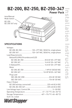
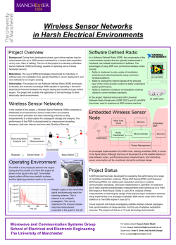
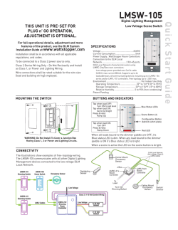
For full operational details, adjustment and more
features of the product, see the DLM System Installation
Guide supplied with the LMRC-102 and also available at
www.wattstopper.com
INSTALLATION SHALL BE
IN ACCORDANCE WITH ALL
APPLICABLE REGULATIONS,
LOCAL AND NEC CODES.
For Class 2 Device Wiring Only –
Do Not Reclassify and Install as
Class 1, or Power and Lighting
Wiring.
Intended for Listed Class 2 DLM
Devices.
Wire connections shall be rated
suitable for the wire size (lead
and building wiring) employed.
For Class 2 DLM devices To be connected to a Class 2
power source only.
Digital Lighting Management
Dual Technology Ceiling Mount
Occupancy Sensor
Voltage:......................................................................................24VDC
Current Consumption:................................................................20mA
Power Supply:.................... Watt Stopper/Legrand Room Controllers
Connection to the DLM Local Network......................... 2 RJ-45 ports
DLM Local Network Characteristics:
Provides low voltage power over Cat 5e cable (LMRJ).
Supports up to 24 communicating devices, including 4
LMRC‑10x or LMPL-101 max per each DLM Local Network
Free topology up to 1,000ft of low voltage cable.
Environment........................................................For Indoor Use Only
Operating Temperature.................. 32° to 131°F (0° to 55°C)
Storage Temperature.....................23° to 176°F (-5° to 80°C)
Relative Humidity......................... 5 to 95% (non condensing)
Patent Pending
SENSOR PLACEMENT (10’ MAX. HEIGHT)
Pendant
fixture
25'
Sensor
6’
Strong air
supply
25'
Mount sensor at least 6’ away from air supply.
Avoid obstacles that block sensor’s line-of-sight.
Sensor
COVERAGE PATTERN
The LMDC-100 provides a 360° coverage pattern.The
coverage shown represents maximum coverage for
walking motion at a mounting height of 10 feet.
25 ft
(7.62m)
PIR
Coverage
Ultrasonic
Coverage
25 ft x 25 ft
(7.62m x 7.62m)
CONNECTIVITY
The illustrations below show examples of free-topology wiring. The LMDC-100 communicates to all other Digital Lighting
Management devices connected to the low voltage DLM Local Network, regardless of their position on the DLM Local Network.
Corner Mount
Sensor
Ceiling Mount
Sensor
DLM Local Network
Low Voltage
LMRJ Cables
Line
Voltage
Line/Hot
Black wire
Neutral
White wire
Room
Controller
J Box
Loads
1
LMRC
102
Switch
Switch
Daylight Sensor
J-Boxes
To
Load
Switch
2
Room
Controller
Red wire
to Load A (1)
Yellow wire
to Load B (2)
Quick Start Guide
LMDC-100
THIS UNIT IS PRE-SET FOR PLUG N’ GO™
OPERATION, ADJUSTMENT IS OPTIONAL.
Ceiling Mount
Occupancy
Sensor
MOUNTING
4" Octagonal J-Box
(at least 1.5" deep)
To octagon box:
Through ceiling tile:
Ceiling hole
Screws
Ceiling
LMRJ cable
LMRJ cable
Rear
housing
Rear
housing
Spring clips (2)
Front cover
Front cover
For applications requiring plenum rating
No box required in non-plenum rated applications
WARNING: A junction box used for sensor installation must not contain any Class 1, Class 3, or other power or
lighting line voltage circuits
Load Parameters
FACTORY PRE-SET OPERATION
Sensor Parameters
T-DELAY
Time Delay
20 minutes
Passive Infrared
Sensitivity
90%
Ultrasonic Sensitivity
70%
ON Mode
Operation*
W-T
Walk Through
OFF
TRIG
Initial Occupancy
PIR and
Ultrasonic
Maintain Occupancy
PIR or
Ultrasonic
RETRIG
TROUBLESHOOTING
Loads do not operate as expected.
LEDs don’t light, display
is off
Load 1
AUTO-ON
Loads 2-8
or more**
MANUAL-ON
if switch is
connected.
Plug Load
AUTO-ON
AUTO-ON
if no switch.
Blink Warning
OFF
OFF
OFF
Daylighting
ON
OFF
OFF
*
Auto-OFF is enabled according to the sensor Time
Delay when a sensor is bound to the load, regardless
of whether the load was turned on automatically with
occupancy or manually using a switch.
** Max 8 loads using LMRC-100 series room controllers.
WARNING: TO CONNECT A COMPUTER TO THE DLM LOCAL
NETWORK USE THE LMCI‑100. NEVER CONNECT THE DLM LOCAL
NETWORK TO AN ETHERNET PORT – DOING SO MAY DAMAGE
COMPUTERS AND OTHER CONNECTED EQUIPMENT.
1.Check to see that the the sensor is connected to the DLM local Network.
2.Check for 24VDC input to the sensor: Plug in a different DLM device at the sensor location.
If the device does not power up, 24VDC is not present.
• Check the high voltage connections to the room controller.
• If high voltage connections are good and high voltage is present, recheck DLM local
Network connections between the sensor and the room controller.
The wrong lights are
controlled
1.Configure the sensor to control the desired lights using the Push n’ Learn adjustment
procedure.
LEDs turn ON and OFF but
load doesn’t switch
1.Make sure device is not in PnL.
2.Check load connections to room controller.
2800 De La Cruz Blvd.
Santa Clara, CA 95050
Phone: 800.879.8585
www.wattstopper.com
10/2014
11434r2
Please
Recycle


© Copyright 2026