
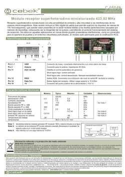
Conexión Eléctrica: Todos los modelos. Conectar
J3J3CV2
J3/J3C INSTRUCCIONES DE INSTALACIÓN
LEA ATENTAMENTE ESTAS INSTRUCCIONES ANTES DE LA CONEXIÓN DEL ACTUADOR. EL INCUMPLIMIENTO DE ESTAS INSTRUCCIONES DEJA SIN EFECTO TODO TIPO DE GARANTÍA.
Los actuadores J+J series J3 y J3C utilizan energía eléctrica para su funcionamiento. Recordamos que tan solo personal especializado efectúe las conexiones o ajustes del actuador.
El actuador eléctrico dispone de elementos exteriores, cada uno con una función diferente. A continuación explicaremos la función de cada uno y como manipularlos.
1.- CONECTORES:
Atención: Antes de conectar el actuador a la corriente, comprobar que el voltaje que figura en la etiqueta de
características (situada en una de las caras exteriores del actuador) corresponda al voltaje que va a ser utilizado.
Los conectores de la series J3C permiten un diámetro de cable manguera entre un máximo y un mínimo para
conservar una buena estanqueidad. El siguiente cuadro nos indica los diámetros.
FIGURA 1
J3/J3C 20/85
CONECTOR
FIGURA 2
1 Junta
2 Base conector
3 Tornillo fijación cable
4 Conector
5 Grapa sujeción
6 Arandela
7 Tuerca
8 Tornillo fijación
9 Arandela
10 Junta tornillo
ACTUADOR DPS2005
ACTUADOR ON-OFF
J3C 140/300
J3/J3C 20/85
J3C-140/300
NEGRO PEQUEÑO
GRIS GRANDE
NEGRO GRANDE
DIN-43650 ISO 4400 & C192
DIN-43650 ISO 4400 & C183
DIN-43650 ISO 4400 & C183
MODELO
min Ø
máx. Ø
min Ø
máx. Ø
J3 20 a J3 85 / J3C 20 a J3C 85
5mm
6mm
8mm
10.5mm
8mm
10.5mm
J3C 140 a J3C 300
min Ø
máx. Ø
8mm
10.5mm
FUSE
FIGURA 4
Conectar el voltaje al conector gris. (Ver Fig.3)
PIN 1 NEUTRO + PIN 2 FASE = ACTUADOR CIERRA
PIN 1 NEUTRO + PIN 3 FASE = ACTUADOR CIERRA
CONECTAR PIN SOBRANTE CON CABLE TIERRA
Conectar la confirmación de posición al conector negro (Ver Fig.4)
PIN 1 COMÚN + PIN 2 = CONFIRMACIÓN POSICIÓN CERRADO
PIN 1 COMÚN + PIN 3 = CONFIRMACIÓN POSICIÓN ABIERTO
FIGURA 3.1
CONEXIONES ELÉCTRICAS ACTUADOR ON/OFF
CONEXIONES ELÉCTRICAS ACTUADOR DPS2005
Conectar el voltaje al conector gris. (Ver Fig.3.1)
PIN 1 NEUTRO + PIN 2 FASE = ALIMENTACION.
CONECTAR PIN SOBRANTE CON CABLE TIERRA
FIGURA 3.2
FIGURA 3
FUSE
Conectar las señales de entrada salida posicionador.
Conector central.(Ver Fig.3.2)
PIN 1 NEGATIVO + PIN 2 POSITIVO = ENTRADA 4/20mA o 0/10V
PIN 1 NEGATIVO + PIN 3 POSITIVO = SALIDA 4/20mA o 0/10V
FIGURA 4.1
* Para otras opciones de conexionados consultar al distribuidor.
Conectar la confirmación de posición al conector negro lateral. (Ver Fig.4.1)
Al finalizar las conexiones debemos conectar los conectores externos a sus respectivas bases.
PIN 1 COMÚN + PIN 2 = CONFIRMACIÓN POSICIÓN CERRADO
Es muy importante asegurarse de que el montaje, tanto del conector con el cable, como del conector con
PIN 1 COMÚN + PIN 3 = CONFIRMACIÓN POSICIÓN ABIERTO
la base tengan las respectivas juntas bien montadas (número 1 y 5 de la Fig. 2)
2.– INDICADOR VISUAL:
La barra amarilla nos indica la posición del actuador y el sentido de rotación (Fig. 5). Cuando la barra amarilla esté señalando “90”,
significa que se encuentra en posición de abierto y si indica “0” significa que se encuentra en posición de cerrado. Si el sentido de
rotación del indicador visual es el actuador está cerrando, por lo contrario, si el sentido de rotación del indicador es el actuador
está abriendo.
3.– MANDO MANUAL DE EMERGENCIA:
FIGURA 6
J3-20
J3-20/J3C-20/85
J3C-20/85
J3C-140/300
FIGURA 5
Conexión Eléctrica: Todos los modelos.
En uno de los lados del actuador se encuentra la palanca selectora. (Ver Fig 6).
AUTO = Operación Automática.
MAN = Operación Manual.
J3C-140/300
ATENCIÓN, no desatornillar nunca el tornillo de seguridad de la palanca selectora, ni utilizar ninguna herramienta para moverla, ya que pueden producirse importantes daños en el sistema mecánico.
Cuando el actuador se encuentra en posición “AUTO”, el movimiento del mismo es controlado por las señales eléctricas enviadas al actuador, cuyos movimientos se encuentran, asimismo, controlados por los
interruptores de final de carrera, operados por las levas, situadas internamente solidarias al eje del indicador de posición.
“MANDO MANUAL DE EMERGENCIA” Si el volante gira durante la operación automática, nunca debe ser obstruido o detenido este movimiento.
Cuando la palanca selectora se encuentra en posición “MAN”:
1) El sistema electrónico desactiva la alimentación eléctrica una vez transcurrido el tiempo configurado en el actuador.
2) La conexión mecánica entre el motor y el eje principal queda desactivada.
3) Accionando manualmente el volante puede situarse la válvula en la posición deseada.
4) Si la palanca selectora se encuentra en “MAN” hay dos opciones para reactivar el motor:
a) Con el actuador en posición “MAN” accionar el volante hacia una de las posiciones finales (cerrado o abierto), si el interruptor correspondiente está activado el motor girará, entonces llevar la palanca selectora de la posición “MAN” a la posición “AUTO” y la unidad estará preparada para operar automáticamente.
b) Posicionar la palanca selectora de “·MAN” a “AUTO”. Desactivar la alimentación eléctrica durante unos segundos para reiniciar el equipo, a continuación la unidad se encuentra lista para operar en automático.
Una vez finalizada la acción manual, deberemos volver a situar la palanca selectora en posición “AUTO”, de no ser así, el actuador no responderá a las señales de apertura ni a las de cierre.
ATC es el sistema encargado de la regulación o control automático de la temperatura interna, está integrado y se activa mientras el actuador está bajo tensión. Por lo tanto recomendamos que, una vez efectuada
la maniobra de apertura o de cierre, el panel de control mantenga la alimentación eléctrica, de lo contrario el sistema ATC quedaría inactivo.
5-INDICADOR LUMINOSO:
Es un sistema de comunicación entre el actuador y el usuario. Según el tipo de lumínica nos informa de:
Tiempo: 200mSeg. por cada dígito de la configuración.
Configuración: dígito 1= led encendido, dígito 0=led apagado.
La configuración es una secuencia repetitiva que consta de cuatro columnas de cuatro dígitos.
J3-20/J3C-20/85
J3C-140/300
ESTATUS OPERACIONAL DEL ACTUADOR
Actuador sin alimentación
Actuador con alimentación
Actuador, maniobra de ….. .a …., (led intermitente)
Actuador limitando, maniobra de …. a…..,(led intermitente)
TIEMPO
100%
100%
100%
200 mSeg.
LED ROJO
0000 0000 0000 0000
1111 1111 1111 1111
1111 1111 1111 1111
1010 1010 1010 1010
Desconexión de motor por tiempo
200 mSeg.
1111 0111 1000 0000
NARANJA, LED APAGADO
Actuador sin alimentación. Funciona con el BSR. Max. 3 min.
Protección baterías. Peligro baterías con poca carga. BSR bloqueado.
Actuador con DPS2005
200 mSeg.
200 mSeg.
200 mSeg.
1000 0000 0000 0000
1010 1000 0000 0000
1111 1111 1111 1111
BSR NC = ROJO, APAGADO / BSR NO = VERDE, APAGADO
6– OPCIÓN BSR:
Si la unidad dispone de un sistema BSR, en caso de fallo de alimentación, el actuador irá a la posición predeterminada.
“NO” normalmente abierto o “NC” normalmente cerrado.
7-KITS BSR / KIT DPS2005
Para realizar el montaje de los kits, consultar los manuales en la web www.jjbcn.com
LED COLORES
LED APAGADO
ABIERTO=LED VERDE / CERRADO LED ROJO
DE ABRIR A CERRAR=ROJO, NARANJA / DE CERRAR A ABRIR=VERDE, NARANJA
DE ABRIR A CERRAR=ROJO, APAGADO / CERRAR A ABRIR=VERDE, APAGADO
NARANJA, APAGADO
PARADO=AZUL / ABRIENDO=AZUL, VERDE / CERRANDO=AZUL, ROJO
FIGURA 7
4-MONTAJE DE LOS COMPONENTES AL ACTUADOR:
Es vital que el “KIT” de montaje para ensamblar el actuador a la válvula esté correctamente mecanizado y montado. Los taladros de las torretas/soportes deben de estar perfectamente mecanizados y alineados
para asegurar precisamente el perfecto alineamiento entre el actuador, las piezas de conexión y la válvula. La parte final del cuadrado macho de la pieza de conexión intermedia no debe tener mayor longitud que
la máxima profundidad del cuadrado de salida del actuador.
Los taladros de montaje del actuador son conformes a las normas ISO 5211 y las salidas cuadradas hembra lo son también con la norma DIN 3337. Recomendamos que las válvulas o elementos a ser actuador
cumplan también la norma ISO 5211, para así facilitar el montaje.
* En caso de fallo en la alimentación eléctrica, el actuador quedará detenido en la posición en la que se encuentre, continuando en el mismo sentido de giro, cuando reciba de nuevo la señal eléctrica.
Los actuadores J3C están libres de mantenimiento. Utilizar sólo detergentes neutros para su limpieza exterior.
MUY IMPORTANTE: Comprobar que ningún objeto (herramientas, trapos, etc.) obstruya el componente a actuar (válvula, dámper, etc.). A continuación poner en funcionamiento el actuador. Pueden producirse importantes desperfectos en el actuador si éste no es operado correctamente. No conectar nunca el actuador de forma que no sea la indicada en el diagrama de conexiones. Todas las unidades están provistas
de una etiqueta externa con el diagrama de conexiones. En caso de duda compruebe y/o consulte las conexiones ANTES de poner en marcha el actuador. Recomendamos que el actuador tenga un sistema independiente de fusibles para protegerle de otros aparatos eléctricos en línea (p.e. bombas).
J3/J3C INSTALLATION INSTRUCTIONS
J3 and J3C Electric actuators operate with the use of live electricity. It is recommended that only qualified electrical engineers be allowed to connect or adjust these actuators. Always ensure that the power
supply is disconnected prior to removing the top cover by disconnecting the DIN power input plug. It is strongly recommended that each actuator has its own independent fuse system to protect it from the
electrical influence of other electrical devices (EG: pumps).
DPS2005 ACTUATOR
ON-OFF ACTUATOR
1.- ELECTRICAL CONNECTORS:
Warning: Before connecting ensure that the voltage to be applied to the actuator is within the range shown on
the identification label. The supplied electrical connectors used to connect to the actuator are DIN plugs. Ensure
the diameter of cable to be used conforms to the maximum and minimum requirements of the DIN plugs to
maintain water tightness.
J3/J3C 20/85
CONNECTOR
FIGURA 2
1 Gasket
2 Terminal strip
3 Cable fixing screws
4 Housing
5 Grommet
6 Washer
7 Gland - nut
8 Fixing screw
9 O-ring
10 Gasket
J3C 140/300
J3/J3C 20/85
J3C-140/300
SMALL BLACK
BIG GREY
BIG BLACK
DIN-43650 ISO 4400 & C192
DIN-43650 ISO 4400 & C183
DIN-43650 ISO 4400 & C183
MODEL
min Ø
máx. Ø
min Ø
máx. Ø
J3 20 to J3 85 / J3C 20 to J3C 85
5mm
6mm
8mm
10.5mm
8mm
10.5mm
J3C 140 to J3C 300
FIGURE 1
READ THESE INSTRUCTIONS BEFORE CONNECTING THE ACTUATOR DAMAGE CAUSED BY NON COMPLIANCE TO THESE INSTRUCTIONS IS NOT COVERED B Y OUR WARRANTY.
min Ø
máx. Ø
8mm
10.5mm
FUSE
Electrical connection: All models.
* For other connection options please contact the vendor.
Warning: Ensure that the square rubber seal is in place when fixing each DIN plug to the actuator.
Failure to do so could allow water ingress and damage
caused by this installation error will invalidate any warranty. The DIN plugs are fixed to their respective bases on the actuator housing with a screw. Do not overtight the screw when assembling.
The power supply is connected to the grey DIN plug. (See Fig.3.1)
NEUTRAL PIN 1 + PHASE PIN 2 = POWER SUPPLY
EARTH/GROUND CONNECTION—FLAT PIN ON TOP
FIGURE 3.2
FIGURE 4
The volt free connection is made to the black DIN plug. (See fig.4)
COMMON PIN 1 + PIN 2 = CLOSED POSITION CONFIRMATION
COMMON PIN 1 + PIN 3 = OPEN POSITION CONFIRMATIÓN
ELECTRICAL CONNECTIONS DPS 2005 ACTUATOR
Connect input and output signal of the DPS 2005.
Connector in the centre .(See Fig.3.2)
NEGATIVE PIN 1 + POSITIVE PIN 2 = 4/20mA or 0/10V INPUT
NEGATIVE PIN 1 + POSITIVE PIN 3 = 4/20mA or 0/10V OUTPUT
Connect the confirmation of position to the black connector on the right. (See
Fig.4.1)
COMMON PIN 1 + PIN 2 = CLOSED POSITION CONFIRMATION
COMMON PIN 1 + PIN 3 = OPEN POSITION CONFIRMATIÓN
FIGURE 4.1
FIGURE 3
The power supply is connected to the grey DIN plug. (See Fig.3)
NEUTRAL PIN 1 + PHASE PIN 2 = CLOSE ACTUATOR
NEUTRAL PIN 1 + PHASE PIN 3 = OPEN ACTUATOR
EARTH/GROUND CONNECTION—FLAT PIN ON TOP
FIGURE 3.1
FUSE
ELECTRICAL CONNECTIONS ON/OFF ACTUATOR
2.- LOCAL VISUAL POSITION INDICATOR:
All J3C actuators are supplied with a local visual position indicator comprises of a black base with a yellow insert that shows both the
position and direction of rotation. (see Fig.5). The open and close positions have the following logos moulded into the top cover
OPEN 90 and CLOSE 0. Opening =
Closing =
J3-20
J3C-20/85
J3C-140/300
FIGURE 5
Anti-condensation protection:
The J3C actuator has an integral thermostatically controlled anti-condensation heater that is automatically activated
whilst main power is applied. The heater does not require a separate supply.
FIGURE 6
3.- EMERGENCY MANUAL OVERRIDE FACILITY:
J3-20/J3C-20/85
J3C-140/300
The J3C has 2 operating modes, automatic and manual , the required mode is
selected by using a lever on the lower half of the actuator housing (see Fig 6).
The 2 positions are marked: AUTO = Automatic operation
MAN = Manual operation
Warning: Do not remove the selector lever securing cross head screw as this will allow its internal mechanism to become loose and will cause irreparable damage to the actuator’s gearbox. Removing this screw
will invalidate the warranty.
When “MAN” function is selected:
1-The electronic system cuts the power to the motor after a few seconds.
2-The motor to output shaft drive is disconnected.
3-The desired position can be achieved by using the manual override lever or hand wheel.
4-There are two ways to re-active the motor after being isolated whilst in “MAN” position:
a) With the actuator in “MAN” function, turn the hand wheel to one of the end positions (opened or closed). If the end position switch is activated the motor stops. Now change the manual override from “MAN”
to “AUTO” , and the actuator is ready to operate automatically again.
b) Change from “MAN” mode to “AUTO” . Deactivate the supply voltage for a few seconds which resets the actuator and it is then change to operate automatically again.
5-EXTERNAL LED LIGHT STATUS:
The LED status light provides visual communication between the actuator and the user.
The current operational status of the actuator is shown by either solidly lit, or different flashing sequences of the LED light:
Time: 200 mSec. X each digit of the configuration.
Configuration: digit 1=LED on, digit 0= LED off
The configuration is a respective sequence of 4 columns of 4 digits.
J3-20/J3C-20/85
J3C-140/300
ACTUATOR OPERATIONAL STATUS
Actuator without power being supplied
Actuator with power being supplied
Actuator , mouving from ….. .to …., (flashing led)
Actuator w torque limit function on, mouving from …. To …..,(flashing led)
TIME
100%
100%
100%
200 mSeg.
RED LED
0000 0000 0000 0000
1111 1111 1111 1111
1111 1111 1111 1111
1010 1010 1010 1010
COLOUR LED
Actuator in MANUAL mode
200 mSeg.
1111 0111 1000 0000
ORANGE, LED OFF
Actuator without power and working with the BSR system. MAX. 3 minutes
Battery protection. Danger - The battery needs recharging. BSR disabled.
Actuator with DPS2005
200 mSeg.
200 mSeg.
200 mSeg.
1000 0000 0000 0000
1010 1000 0000 0000
1111 1111 1111 1111
BSR NC = RED, OFF / BSR NO = GREEN, OFF
LED OFF
OPEN=GREEN LED / CLOSE= RED LED
FROM OPEN TO CLOSE=RED, ORANGE/ FROM CLOSE TO OPEN=GREEN, ORANGE
FROM OPEN TO CLOSE=RED, OFF / FROM CLOSE TO OPEN=GREEN, OFF.
ORANGE, OFF
STOP=BLUE/ OPENING=BLUE, GREEN / CLOSING=BLUE, RED
6-OPCION BSR:
If the actuator is fitted with the BSR (Battery Spring Return) plug-in failsafe system upon electrical failure the actuator will go to the predetermined position: NO (normally opened) or NC (normally closed).
7-KITS BSR / KIT DPS2005
To assemble the kits, consult the manuals on www.jjbcn.com
FIGURE 7
4-MOUNTING TO COMPONENT BEING ACTUATED (Eg:1/4 turn valve).
It is vital that the mounting kit used to connect the electric actuator to the component (eg: valve) is correctly manufactured and assembled. The mounting bracket’s holes must be drilled to ensure that the centerline of the actuator’s drive is perfectly in line with the component’s drive-centerline, and that the drive coupling/ adaptor rotates around this centerline. The mounting holes of the actuator conform to ISO 5211,
and the female output drive conforms to DIN 3337.
We strongly recommend that valves/components to be actuated that have ISO 5211 compliant top works are used wherever possible as it greatly assists in ensuring the concentrity of mounting the actuator to the
valve.
The male square end of the drive coupling MUST NOT be longer than the maximum depth of the actuator female output drive when the assembly is bolted together.
Failure to comply with these instructions will cause uneven wear and dramatically reduce the working life of the valve and actuator.

© Copyright 2026