
LLE-3 • LLE-6 - Digital Lumens
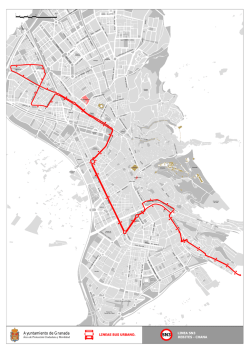
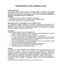
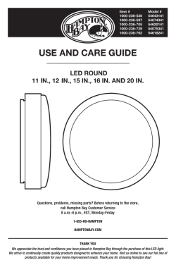
LLE-3 • LLE-6
INSTALLATION INSTRUCTIONS
INSTRUCCIONES DE INSTALACIÓN
PRODUCT SAFETY
! This product must be installed in accordance with the applicable
installation codes by a person familiar with the construction and
operation of the product and the hazards involved.
To avoid risk of electrical shock, disconnect power before installing,
wiring, or servicing the fixture or Digital Light Agent (DLA).
! Do not install fixtures in a vertical or angled orientation.
! Do not apply paint, lubricants, or other coatings to fixture, DLA-
LLE, suspension cables, or fasteners.
! Do not use fixture or DLA-LLE if the housing, suspension cables,
or optics are damaged.
! Use a damp cloth to clean fixture housing.
LLE-3-ST: 120 - 277 V AC 50/60 Hz 0.29 A maximum
LLE-6-ST: 120 - 277 V AC 50/60 Hz 0.55 A maximum
REQUIRED TOOLS:
• Sticker book template (provided by the project manager)
• Phillips ® #2 screwdriver
• Box level (for Standard Aircraft Cable)
• Mounting screws (for Fixed Mount)
!
Read these instructions before using product.
Lea las instrucciones antes de usar el producto.
SEGURIDAD DEL PRODUCTO
! Este producto se debe instalar conforme al código de
instalación correspondiente y dicha instalación debe estar a
cargo de una persona familiarizada con la construcción y la
operación del producto y los riesgos involucrados.
Para evitar descargas eléctricas, desconecte la alimentación
antes de instalar, cablear o realizar tareas de mantenimiento
en el dispositivo o el Digital Light Agent (agente de luz
digital, DLA).
! No instale los dispositivos en posición vertical o en ángulo.
! No aplique pintura, lubricantes ni ningún otro recubrimiento
al dispositivo, al DLA-LLE, a los cables de suspensión o a
los sujetadores.
! No use el dispositivo o el DLA-LLE si la carcasa, los cables
de suspensión o la óptica están dañados.
! Use un paño húmedo para limpiar la carcasa del dispositivo.
LLE-3-ST: 120 - 277 V~ 50/60 Hz 0.29 A máximo
LLE-6-ST: 120 - 277 V~ 50/60 Hz 0.55 A máximo
HERRAMIENTAS NECESARIAS
• Plantilla del libro de etiquetas adhesivas (proporcionada por
el director del proyecto)
INSTALLATION GUIDELINES
• Destornillador Phillips ® n.º 2
Some steps, including fixture installation, power/data connection, as
well as connection to facility mains power, may vary depending on the
project design and conditions.
• Tornillos de montaje (si está colgado mediante un
montaje fijo)
Power and Data Limits
• Caja niveladora (para el cable para aviación estándar)
PAUTAS DE INSTALACIÓN
A single DLA-LLE can control up to 15 fixtures in a continuous run.
Additionally, up to 15 fixtures can share the same power line between
each LLE’s internal line voltage harness. To power more than 15
fixtures, introduce a new line voltage connection at the sixteenth
fixture.
Algunos pasos pueden variar según el diseño y las condiciones
del proyecto (p. ej., la instalación de dispositivos, la conexión
de los cables de datos y de alimentación, y la conexión a la red
eléctrica en la ubicación física).
Hardware Spacing and Orientation
Límites de alimentación y datos
Fixture orientation must enable correct power and data connections.
Fixture spacing must account for DLA-LLEs to be installed after the
fixtures are hung, according to the project design. The length of
each DLA-LLE module is 2.8 in (7.1 cm) when installed between two
fixtures.
The length of each LLE fixture is 48.5 in (123.2 cm).
! 2.8 in (7,1 cm)
Un solo DLA-LLE puede controlar hasta 15 dispositivos que
funcionen de forma continua. Además, hasta 15 dispositivos
pueden compartir la misma línea de alimentación entre los cables
de tensión de línea interna del LLE. Para suministrar alimentación
a más de 15 dispositivos, instale una nueva conexión de tensión
de línea en el decimosexto dispositivo.
Orientación y espaciado del equipo f ísico
La orientación del dispositivo debe permitir conectar
correctamente los cables de alimentación y de datos. Para la
separación de los dispositivos es importante tener en cuenta que,
según el plan del proyecto, los módulos DLA-LLE se instalarán
después de colgar los dispositivos. La longitud de cada módulo
DLA-LLE es de 7,1 cm cuando se instala entre dos dispositivos.
La longitud de cada dispositivo LLE es de 123,2 cm.
www.digitallumens.com
+1 (617) 723-1200
VERIFY THE FIXTURE AND MODULE ORIENTATION
VERIFICAR L A ORIENTACIÓN DEL DISPOSITIVO Y DEL MÓDULO
Each LLE fixture and DLA-LLE module have two unique ends, Side A and Side B.
Los dispositivos LLE y los módulos DLA-LLE tienen cada uno dos extremos únicos, el lado A y el lado B.
DLA-LLE Side A:
Lado A del DLA-LLE:
DLA-LLE Side B:
Lado B del DLA-LLE:
• Receives power from LLE fixture.
Recibe alimentación del dispositivo LLE.
• Facilitates data connection.
Facilita la conexión de datos.
• Facilitates data connection.
Facilita la conexión de datos.
• Attaches to side B of an LLE fixture.
Se conecta al lado B de otro
dispositivo LLE.
• Attaches to side A of an LLE fixture.
Se conecta al lado A de otro
dispositivo LLE.
LLE Side A:
Lado A del LLE:
• Facilitates data connection.
Facilita la conexión de datos.
• Facilitates line voltage connection to an adjacent fixture
or from the supply circuit.
Facilita la conexión de voltaje de línea a un dispositivo
adyacente o desde el circuito de alimentación.
• Attaches to side B of another LLE fixture or DLA-LLE
module.
Se conecta al lado B de otro dispositivo LLE o módulo DLALLE.
LLE Side B:
Lado B del LLE:
• Provides power to an adjacent DLA-LLE module.
Suministra alimentación a un módulo DLA-LLE adyacente.
• Facilitates data connection.
Facilita la conexión de datos.
• Facilitates line voltage connection to an adjacent fixture or
from the supply circuit.
Facilita la conexión de voltaje de línea a un dispositivo
adyacente o desde el circuito de alimentación.
• Attaches to side A of another LLE fixture or DLA-LLE
module.
Se conecta al lado A de otro dispositivo LLE o módulo DLALLE.
2
LLE Installation Instructions (Nor th America) | Instrucciones de instalación (América del Nor te)
ADD TRACKING LABELS TO THE STICKER BOOK
AGREGAR L AS ETIQUETAS DE SEGUIMIENTO EN EL LIBRO DE ETIQUETAS ADHESIVAS
1. Detach the plastic bag from the DLA-LLE module containing the barcode label.
Retire la bolsa de plástico del módulo DLA-LLE que contiene la etiqueta del código de
barras.
2. Affix the barcode label to the sticker book in accordance with the physical location of
the DLA-LLE module in the facility.
Pegue la etiqueta del código de barras al libro de etiquetas adhesivas según la ubicación
física del módulo DLA-LLE.
3. Repeat for each DLA-LLE module and its assigned fixture run.
Repita la acción para cada módulo DLA-LLE y su serie de dispositivos asignada.
Sticker Book
Libro de etiquetas adhesivas
Note: Ensure that you have labeled each fixture run clearly as this information is necessary
for wiring and data configuration.
Nota: Asegúrese de haber etiquetado claramente cada serie de dispositivos, ya que esta
información es necesaria para la configuración de datos y del cableado.
LLE-3 | LLE-6
3
INSTALL THE FIXTURES
INSTAL AR LOS DISPOSITIVOS
There are two hanging methods: Fixed Mount and Standard Aircraft Cable.
Hay dos métodos: montaje fijo y cable para aviación estándar.
Note: Leave 2.8 in (7.1 cm) between fixtures where DLA-LLE modules will be installed, according to the project design.
Nota: Deje 7,1 cm de separación entre los dispositivos donde se instalarán módulos DLA-LLE (según el diseño del proyecto).
Fixed Mount (to surface or unistrut):
Montaje f ijo (a la superf icie o Unistrut):
1. Refer to the sticker book to confirm the correct location of the fixture.
39.375 in ± .375 in
100,0 cm ± 1,0 cm
Consulte el libro de etiquetas adhesivas para confirmar la ubicación
correcta del dispositivo.
2. Install both mounting brackets so that they will be equidistant from the
center of the fixture, leaving 39.375 ± .375 in (100.1 ± 1.0 cm)
between brackets.
Instale ambos soportes de montaje de manera que queden equidistantes
desde el centro del dispositivo y deje 100,1 ± 1,0 cm entre los soportes.
3. Secure the fixture to the mounting brackets through the designated
handles so that the hardware snaps into place.
Fije el dispositivo a los soportes de montaje a través de las manijas
designadas de manera que el equipo físico se coloque en su lugar.
4. Center the fixture, then use a Phillips ® #2 screwdriver and the provided
locking screws to lock the fixture to the brackets.
Centre el dispositivo y fíjelo en los soportes con un destornillador Phillips ®
n.º 2 y los tornillos de retención.
4
Fixed Mount Locking Screws
Tornillos de retención del montaje f ijo
LLE Installation Instructions (Nor th America) | Instrucciones de instalación (América del Nor te)
Standard Aircraft Cable:
Cable para aviación estándar:
Note: Each fixture requires at least two suspension cables, two cable fasteners, and two Gripple ® spring clips.
Nota: Cada dispositivo necesita, por lo menos, dos cables de suspensión, dos sujetadores de cable y dos abrazaderas de resorte Gripple ® .
1. Refer to the sticker book to confirm the correct location of the fixture.
Consulte el libro de etiquetas adhesivas para confirmar la ubicación
correcta del dispositivo.
2. Secure the suspension cables to a beam or truss.
Asegure los cables de suspensión a la viga o a la armadura de cubierta.
Suspension Cable to Beam/Truss
Cable de suspensión a la viga/
armadura de cubierta
3. Attach the spring clips to the fixture using the designated holes.
Conecte las abrazaderas de resorte al dispositivo mediante
los orificios designados.
4. Hook the suspension cables to the spring clips.
Cuelgue los cables de suspensión a las abrazaderas de resorte.
5. Use a box level to level the fixture.
Utilice una caja niveladora para nivelar el dispositivo.
! Note maximum cable angle.
Tenga en cuenta el ángulo máximo del cable.
!
60° max.
60° máx.
LLE-3 | LLE-6
5
MAKE POWER AND DATA CONNECTIONS
CONEXIÓN DE LOS CABLES DE ALIMENTACIÓN Y DE DATOS
Note: Before making data connections, refer to the sticker book or project plan to identify all assigned control groups. There must be one
continuous data line between all fixtures assigned to the same DLA-LLE.
Nota: Antes de realizar conexiones de datos, consulte el libro de etiquetas adhesivas o el plan del proyecto para identificar todos los grupos de
control asignados. Debe haber una línea de datos continua entre todos los dispositivos asignados al mismo DLA-LLE.
*Control power (black/red) cables provide power from a
f ixture to a DLA-LLE module. If no DLA-LLE is present,
tuck the cables into the f ixture.
*Los cables de alimentación de control (negro/rojo)
suministran alimentación desde un dispositivo a un
módulo DLA-LLE. Si no hay presente un DLA-LLE,
introduzca los cables en el dispositivo.
CONTROL
CONTROL
Power (black/red)
Alimentacion (negro/rojo)
Data (yellow/white)
Datos (amarillo/blanco)
LINE POWER
LÍNEA DE ALIMENTACIÓN
Line (brown)
Línea (marrón)
Ground (green/yellow)
Tierra (verde/amarillo)
Neutral (blue)
Neutro (azul)
Fixture to Fixture:
De dispositivo a dispositivo:
1. In accordance with national, state and local electrical codes, gather
the line power and control data (yellow/white) cables from each
fixture and make the appropriate connections.
Para cumplir con las normativas de electricidad locales, regionales y
nacionales, agrupe los cables de la línea de alimentación y de datos de
control (amarillo/blanco) de cada dispositivo y realice las
conexiones adecuadas.
2. Once the power and data lines are connected, hook the tab on Side
A of the fixture onto Side B of the next fixture.
Después de conectar las líneas de datos y de alimentación, enganche la
pestaña del lado A del dispositivo en el lado B del dispositivo siguiente.
3. Using a Phillips ® #2 screwdriver, secure the endplates together with
the provided screws.
Use un destornillador Phillips ® n.º 2 para fijar las placas de los extremos
con los tornillos suministrados.
Side A
4. Connect all fixtures and DLA-LLE modules in a fixture run. Make any
necessary knockouts (see Connect to Facility Mains Power, page 8)
and secure cover plates to fixtures or modules on either end of the
fixture run.
Conecte todos los dispositivos y los módulos DLA-LLE en una serie
de dispositivos. Realice los orificios necesarios (consulte el apartado
Conexión a la red eléctrica en la ubicación física, en la página 8) y fije
las placas de protección en los dispositivos o en los módulos de uno de
los extremos de la serie de dispositivos.
6
LLE Installation Instructions (Nor th America) | Instrucciones de instalación (América del Nor te)
Side B
Fixture to DLA-LLE (to Fixture):
Dispositivo a DLA-LLE (a
dispositivo):
CONTROL
CONTROL
Power (black/red)
Alimentacion (negro/rojo)
Data (yellow/white)
Datos (amarillo/blanco)
LINE POWER
LÍNEA DE ALIMENTACIÓN
Line (brown)
Línea (marrón)
Ground (green/yellow)
Tierra (verde/amarillo)
\
Neutral (blue)
Neutro (azul)
1. If connecting line power between two fixtures: In accordance with
national, state and local electrical codes, feed the line power cables
from the first fixture through the DLA-LLE. Connect to the second
fixture.
Si se conecta la línea de alimentación entre dos dispositivos: Para cumplir
con las normativas de electricidad locales, regionales y nacionales, pase
los cables de la línea de alimentación del dispositivo a través del DLA-LLE.
Conéctelos al segundo dispositivo.
2. Refer to the project plan to verify the control assignments. Feed one
control data (yellow/white) cable through each side of the DLA-LLE,
and connect to the adjacent fixture(s). Then, feed the control power
(black/red) cable to connect with the appropriate fixture.
Compruebe las asignaciones de control en el plan del proyecto. Pase un
cable de datos de control (amarillo o blanco) por cada uno de los lados
del DLA-LLE y conéctelos a los dispositivos adyacentes. A continuación,
pase el cable de alimentación de control (negro o rojo) para conectarlo al
dispositivo adecuado.
Note: A continuous data bus is required for all fixtures in a DLA-LLE
control group. Familiarize yourself with the project design to avoid
connecting one fixture to multiple DLA-LLEs.
Nota: Se requiere un bus de datos continuo para todos los dispositivos
que pertenezcan a un grupo de control de DLA-LLE. Familiarícese con el
diseño del proyecto para evitar conectar un dispositivo a varios DLA-LLE.
3. Once all connections are made, hook the tab on Side A of the DLA-LLE
onto Side B of the adjacent fixture.
Después de completar todas las conexiones, enganche la pestaña del
lado A del DLA-LLE en el lado B del dispositivo adyacente.
4. Using a Phillips ® #2 screwdriver, secure the endplates together with the
provided screws.
Use un destornillador Phillips ® n.º 2 para fijar las placas de los extremos
con los tornillos suministrados.
Side A
Lado A
Side B
Lado B
5. Connect all fixtures and DLA-LLE modules in a fixture run. Make any
necessary knockouts (see Connect to Facility Mains Power, page 8) and
secure cover plates to fixtures or modules on either end of the
fixture run.
Conecte todos los dispositivos y los módulos DLA-LLE en una serie
de dispositivos. Realice los orificios necesarios (consulte el apartado
Conexión a la red eléctrica en la ubicación física, en la página 8) y fije las
placas de protección en los dispositivos o en los módulos de uno de los
extremos de la serie de dispositivos.
LLE-3 | LLE-6
7
CONNECT TO FACILITY MAINS POWER
CONEXIÓN A L A RED ELÉCTRICA EN L A UBICACIÓN FÍSICA
Do not connect or disconnect while under load.
No debe conectarse o desconectarse mientras esté en funcionamiento.
Knockout Locations:
Ubicaciones de los orif icios:
LLE (Top View) Knockout Locations
Ubicaciones de los orif icios en el LLE (vista superior)
½ inch trade size
Tamaño comercial de 1,27 cm
Cover Plate Knockout Locations
Ubicaciones de los orif icios para
las placas de protección
To connect through knockout on top of f ixture:
Para realizar la conexión a través del orif icio en la parte superior del dispositivo:
1. Make the appropriate knockout, then use a Phillips ® #2 screwdriver to remove the (4x) screws to
open the top of the fixture.
Realice el orificio correspondiente y, a continuación, use un destornillador Phillips ® n.º 2 para retirar
los 4 tornillos y abrir la parte superior del dispositivo.
2. Identify the power lines that will attach to facility mains power and cut off the modular connector.
Identifique las líneas de alimentación que se conectarán a la red eléctrica en la ubicación física y
recorte el conector modular.
3. Feed the wires through the knockout and strain relief.
Pase los cables a través del orificio y del protector para cables.
4. In accordance with national, state, and local electrical codes, connect to facility mains power.
Para cumplir con las normativas de electricidad locales, regionales y nacionales, conecte los cables a la
red eléctrica en la ubicación física.
5. Replace the fixture top and screws.
Sustituya los tornillos y la parte superior del dispositivo.
8
LLE Installation Instructions (Nor th America) | Instrucciones de instalación (América del Nor te)
Cut modular connector
Corte el conector modular
To connect through knockout on cover plate:
Para realizar la conexión a través del orif icio en la placa de protección:
1. Identify the power lines that will attach to facility mains power and cut off the
modular connector.
Identifique las líneas de alimentación que se conectarán a la red eléctrica en la ubicación física y
recorte el conector modular.
2. Feed the wires through the knockout and strain relief.
Pase los cables a través del orificio y del protector para cables.
Cut modular connector
Corte el conector modular
3. In accordance with national, state, and local electrical code, connect to facility mains power.
Para cumplir con las normativas de electricidad locales, regionales y nacionales, conecte los
cables a la red eléctrica en la ubicación física.
4. Attach the cover plate by inserting the two bottom tabs to the fixture.
Para sujetar la placa de protección, inserte las dos pestañas inferiores en el dispositivo.
5. Using a Phillips ® #2 screwdriver and the provided screws, screw the cover plate to the fixture.
Atornille la placa de protección al dispositivo con un destornillador Phillips ® n.º 2.
LLE-3 | LLE-6
9
VERIFY THE STICKER BOOK
VERIFICAR EL LIBRO DE ETIQUETAS ADHESIVAS
To prevent issues during commissioning, ensure that the placement of the bar code label in the sticker
book corresponds to the DLA-LLE’s physical location in the facility and that the corresponding fixture
runs are identified.
Para evitar inconvenientes durante la puesta en marcha, asegúrese de que la ubicación de la etiqueta del
código de barras en el libro de etiquetas adhesivas corresponda a la ubicación física del DLA-LLE en la
instalación y de que se hayan identificado las series de dispositivos correspondientes.
Sticker Book
Libro de etiquetas adhesivas
PROGRAM THE DLA-LLE
PROGR AMAR EL DL A-LLE
1. Verify that the DLA-LLE module is powered ON.
Verifique que el módulo DLA-LLE esté encendido.
2. Use the USB Wireless Adapter and Commissioner software to program the DLA-LLE.
Utilice el software Commissioner y el adaptador inalámbrico con conexión USB para programar el DLA-LLE.
Importador mexicano
H20 Arquitecteros
Nuevo León #501 A
Col. Alameda
Celaya, Guanajuato
México C.P. 38050
Tel.: +52 (461) 613 3751
www.digitallumens.com
374 Congress Street, Suite 600
Boston, MA USA 02210
+1 (617) 723-1200
All Rights Reserved © 2010-2015
Digital Lumens Incorporated
Subject to change without notice.
DOC-000279-00 Rev D 02-2015


© Copyright 2026