
Italiano
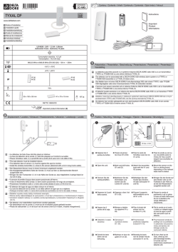
Italiano
COMANDO ELETTRONICO AUTOMATICO
“T” TYPE
Code 35169492-001
COMANDO AUTOMATICO CON TERMOSTATO ELETTRONICO
MANUALE D’USO
AUTOMATIC CONTROL WITH ELECTRONIC THERMOSTAT
INSTRUCTION MANUAL
STEUERUNG AUTOMATIKBETRIEB MIT ELEKTRONISCHEM
THERMOSTATBEIDENUNGSLEITUNG
COMMANDE AUTOMATIQUE AVEC THERMOSTAT ELECTRONIQUE
MANUAL D’UTILISATION
MANDO AUTOMATICO CON TERMOSTATO ELECTRÓNICO
MANUAL DE USO
AUTOMATISCHE BEDIENING MET ELEKTRONISCHE THERMOSTAAT
GEBRUIKSHANDLEIDING
Per i collegamenti elettrici vedere manuale d’uso
UNT-SVX03E-XX
For the wiring diagrams see instruction manual
UNT-SVX03E-XX
Fur die elektroanschlusse siehe bedienungsanleitung
UNT-SVX03E-XX
Pour le connexions electriques voir le manual d’etreitien
UNT-SVX03E-XX
Par las conexion elèctricas ver los manual de uso
UNT-SVX03E-XX
Voor de elektrische aansluitingen zie gebruikshandleiding
UNT-SVX03E-XX
Cod. ASA66801
UNT-SVU008-XX_0906
• PRESENTAZIONE
Grazie ad una progettazione d’avanguardia è stato realizzato per il
ventilconvettore cassette CWS Trane un comando elettronico automatico
facilmente programmabile e con elevato grado di sensibilità.
Con questo comando, gestito da microprocessore, è possibile realizzare
il controllo del ventilconvettore grazie alle numerose funzioni ed opzioni
previste.
Le funzioni base del comando sono:
• Accensione e spegnimento del ventilconvettore
• Controllo della temperatura ambiente
• Impostazione della temperatura ambiente desiderata (SET)
• Possibilità di selezionare il ciclo di funzionamento estivo o invernale
direttamente dai commutatori del comando, oppure, con un segnale
elettrico, dalla centrale termica o, negli impianti a due tubi, in modo
automatico tramite un CHANGE-OVER in base alla impostazione
selezionata da un Jumper (J1) interno al comando.
• Selezione manuale delle tre velocità del ventilatore.
• Selezione automatica delle tre velocità del ventilatore in funzione dello
scostamento esistente fra la temperatura impostata come set e quella
ambiente.
• Comando termostatico di apertura o chiusura (ON-OFF), sia nel ciclo
estivo che in quello invernale, della valvola acqua (impianto a due tubi)
o delle due valvole (impianto a quattro tubi).
• Negli impianti a quattro tubi con ventilconvettori corredati di valvole acqua
ON-OFF e con presenza costante dei due fluidi (acqua calda e acqua
fredda) nei circuiti, è possibile ottenere la commutazione automatica
dalla fase riscaldamento a quella di raffreddamento , e viceversa, in
funzione dello scostamento esistente fra la temperatura ambiente e la
temperatura settata, con zona morta di ~2°C.
• Collegando la sonda di minima (accessorio MWT posta tra le alette della
batteria di scambio termico), nel solo ciclo invernale, il ventilatore entrerà
in funzione solamente se la temperatura dell’acqua è superiore a 42°C
e verrà fermato quando quest’ultima è inferiore a 38°C.
ATTENZIONE: con comando in OFF il ventilconvettore è ancora
alimentato a 230V. Per qualsiasi manutenzione assicurarsi di aver
tolto la tensione.
Prima di chiudere il comando, verificare che la configurazione di default
dei Dip-Switch e del Jumper posti sulla scheda elettronica (vedi disegno
“Configurazione di default DIP-SWITCH” e Jumper a pag.3) soddisfi le
proprie esigenze; in caso contrario programmare il controllo in relazione
alle funzioni desiderate.
IMPOSTAZIONI DELLE FUNZIONI
• Tipo di termostatazione ON / OFF :
1) sul motore = polo n°1 in ON e n°2 in ON
2) sulle valvole = polo n°1 in OFF e n°2 in ON
3) sulle valvole e sul motore in maniera contemporanea = polo n°1 in ON e n°2 in OFF
4) commutazione automatica estate / inverno con zona morta solo per
impianti a due valvole = polo n°1 in OFF , n°2 in OFF
• Commutazione Estate / Inverno JUMPER J1 :
1) selezionabile tramite il commutatore del comando: Jumper J1 in
posizione di default pin 1-2 chiusi
2) selezionabile con consenso remoto: Jumper J1 in posizione pin 2-3
chiusi (il commutatore estate/inverno non è attivo).
Il comando é predisposto per il funzionamento invernale, alimentando,
con la fase (L 230V), il morsetto del fan coil verrà azionato il selettore
elettronico che commuterà il funzionamento in ciclo estivo (CH).
Solamente sui ventilconvettori alimentati con impianto a due tubi,
l’alimentazione del morsetto può avvenire in modo automatico
applicando, sul tubo che alimenta la batteria, la sonda CHANGE OVER
che chiuderà il contatto elettrico quando la temperatura dell’acqua é
inferiore a 15° C, determinando così, automaticamente, la commutazione
al ciclo di funzionamento estivo.
Commutazione Estate/Inverno locale
Commutazione Estate/Inverno remota
• Sonda di minima temperatura MWT (da posizionarsi tra le alette della
batteria) che con programma di riscaldamento evita che il motore funzioni
con temperatura dell’acqua inferiore a 38 °C :
2
CONFIGURAZIONE DI DEFAULT DIP-SWITCH:
English
AUTOMATIC ELECTRONIC CONTROL
“T” TYPE
Code 35169492-001
Dip. Dip.
1 2
Descrizione delle funzioni
ON ON
Termostatazione sul ventilatore
OFF ON
Termostatazione sulle valvole e funzionamento continuo del
ventilatore
ON OFF Termostatazione contemporanea delle valvole e del ventilatore
OFF OFF Termostatazione sulle valvole, per impianti a 4 tubi, con
commutazione automatica estate-inverno in funzione della
temperatura aria, con zona morta di 2°C.
Posizione sulla scheda dei DIP SWITCH e del ponticello JP (STANDARD)
Dip 1 = ON Dip 2= ON J1= 1-2 chiusi
Dopo aver scelto le funzioni desiderate, montare il comando a parete
facendo attenzione a posizionarlo sulla parete del locale da condizionare
all’altezza di circa 1,5m, su una parete intermedia e lontano da fonti di
calore e da correnti d’aria fredda; collegare la morsettiera M1-M2 posta
sulla scheda elettronica alla morsettiera posta sulla fiancata del
ventilconvettore secondo lo schema selezionato e nel rispetto degli schemi
elettrici (pag.16/17). Per il collegamento tra termostato e ventilconvettore
utilizzare cavi con sezione 0,75 mm2. La eventuale sonda di minima acqua
MWT deve essere collegata alla morsettiera M3.
ATTENZIONE: con comando in OFF il ventil convettore è ancora
alimentato a 230V. Per qualsiasi manutenzione assicurarsi di aver
tolto la tensione.
Per controllare più ventilconvettori da un’unica unità, è nesessario che gli
apparecchi siano corredati di moduli Selettori-ripetitori REL 1.
• CARATTERISTICHE TECNICHE DEL CONTROLLO
1) alimentazione : 230 V.c.a.
2) campo di regolazione del termostato da 15 a 30°C con differenziale1°C
3) temperatura di lavoro 0/ 40 °C
4) temperatura di stoccaggio -20 / + 70 °C
5) contenitore in ABS
6) protezione IP 20
7) connessione tramite morsettiera da circuito stampato
8) n°3 relè da 8 ( 2 ) A. 250V. a.c. (I-II-III velocità motore)
9) n°2 relè da 6 ( 1,5 ) A. 250V. a.c.
10) n° 1 ingresso optoisolato per cambio stagionale remoto
11) n° 1 ingresso sonda di temperatura per rilevamento temperatura acqua
12) Controllo stato sonde: nella situazione in cui la sonda aria risultasse
interrotta o in corto, il comando si predispone in funzionamento
continuo (uscita valvole eccitate e ventilazione attiva) ed il led rosso
posto sul frontalino del comando inizia a lampeggiare; nella
configurazione “commutazione automatica estate - inverno “ il comando
è disattivo e solo il led lampeggia.
• PROGRAMMA DI LAVORO CON ZONA MORTA
Termostatazione sulle valvole e velocità continua del motore
Dip switch N° 1 off
Dip switch N° 2 off
Con questo programma viene disabilitata la funzione del commutatore
Estate- inverno
Diagramma di funzionamento con zona morta
• INTRODUCTION
Avant-garde design has created an easy to programme and highly sensitive
automatic electronic control for the Trane CWS cassette.
The fan coil can be operated via the numerous functions and options
incorporated in this microprocessor-based control unit.
The basic functions of the control unit consist in:
• Turning the fan coil on and off
• Control room temperature
• Setting and reading the required room temperature (SET)
• Selecting the summer or winter operating cycle directly from the control
switch, via an electric signal from the heating plant, or automatically
using a CHANGEOVER in two-pipe systems, based on the setting
selected by a Jumper (J1) inside the control unit.
• Manual selection of the three fan speeds
• Automatic selection of the three fan speeds according to the difference
between the set temperature and the room temperature.
• In both summer and winter cycle, thermostatic control of opening and
closing (ON/OFF) of the water valve (two-pipe installation) or the two
valves (four-pipe installation).
• in four-pipe fan coils with ON/OFF water valves and the two liquids (hot
and cold water) constantly present in the circuits, automatic switching
between heating and cooling phases according to the difference between
set temperature and room temperature with a dead zone of ~2°C.
• In the winter cycle only, if a minimum sensor is connected (MWT accessory
located between the fins of the heat exchange coil), the fan coil will start
up only if the water temperature rises above 42°C and shut down when
water temperature drops below 38°C.
Attention: with the control unit OFF, the fan coil is still powered by
230 V. Before carrying out maintenance, always isolate from voltage.
Before closing the control unit, check that the default configuration of the
dip switches and the jumper on the electronic board (see drawing “Default
configuration of the dip switches” and Jumper on page 5) satisfies the
requirements of the installation. If not, program the control unit in
accordance with the required functions.
FUNCTION SETTINGS
• Type of ON/OFF thermostatic control
1) on motor = poles 1 to ON and 2 to ON
2) on valves = pole 1 OFF and pole 2 ON
3) on valves and motor simultaneously = pole 1 ON and pole 2 OFF
4) automatic summer/winter switching with dead zone for 2-valve
installations only = pole 1 OFF, pole 2 OFF
• Summer/winter switching JUMPER J1 :
1) can be selected using the control switch: Jumper J1 in default position,
pins 1-2 closed
2) can be selected by remote signal: Jumper J1 between pins 2-3 closed
(the summer/winter switch is disabled)
The control unit is set for winter operation. Supplying line voltage (230V)
to the terminal of the fan coil activates the electronic selector to switch
into summer mode (CH).
In two-tube fan coils only, the terminal may be powered automatically
by means of the change-over. Mounted in contact with the water tube,
this closes the electrical circuit if the temperature drops below 15°C,
automatically switching the unit into summer mode.
Local Summer/Winter switching
Remote Summer/Winter switching
Posizione 3 = Elettrovalvola acqua calda off
Posizione 3’ = Elettrovalvola acqua fredda off
Posizione 4 = Elettrovalvola acqua calda on
Posizione 4’ = Elettrovalvola acqua fredda on
Velocità: I = bassa
II = media
III = alta
3
• MWT minimum temperature sensor (positioned between the fins of the
coil) prevents the motor operating with water temperatures of below 38 °C
4
CONFIGURATION OF DIP SWITCHES
Dip. Dip.
1
2
ON ON
Deutsch
AUTOMATISCHES ELEKTRONIKSTEUERGERÄT
“T“ TYPE
Code 35169492-001
Description of the function
Thermostatic control on the fan
OFF ON Thermostatic control on the valves and continuous fan operation
ON OFF Simultaneous thermostatic control on the valves and fan
OFF OFF Thermostatic control on the valves, for 4-pipe systems, with
automatic summer-winter cycle switching according to the air
temperature, with 2°C dead zone.
Position of the DIP SWITCHES and J1 jumper on the board (STANDARD)
Dip 1 = ON Dip 2= ON J1= 1-2 closed
After choosing the required functions, mount the control unit to the wall,
taking care to position it on an inner wall in the room being air-conditioned
at a height of about 1.5 m, away from sources of heat and currents of cold
air. Connect terminal board M1-M2 on the electronic board to the terminal
board located on the side of the fan coil, according to the selected layout
and following the wiring diagrams (page16/17). For the connection between
the thermostat and the fan coil, use cables with a minimum cross-section
of 0.75 mm2. Any MWT minimum water probe must be connected to terminal
board M3.
ATTENTION: with the control unit on OFF, the fan coil is still supplied
with 230 V. Before carrying out maintenance, always disconnect from
the voltage.
To control a number of fan coils from a single unit, all the units must be
fitted with selector-repeater modules REL 1.
• TECHNICAL CHARACTERISTICS OF THE CONTROL UNIT
1) Power supply: 230 V AC
2) Thermostat control range from 15 to 30°C with differential 1°C
3) Operating temperature 0/40 °C
4) Storage temperature -20/ + 70 °C
5) ABS case
6) Protection class: IP 20
7) Connection via printed circuit terminal board
8) Three 8 (2) A, 250 V AC relays (I-II-III motor speed)
9) Two 6 (1,5) A, 250 V AC relays
10) 1 x optically isolated input for remote seasonal changeover
11) 1 x temperature sensor input for measuring water temperature
12) Probe status control: if the air probe is disconnected or short-circuited,
the control unit switches to continuous operation (valve outputs
energised and fan on) and the red LED on the front of the control unit
starts flashing; in the “automatic summer– winter switching”
configuration, the control unit is disabled and only the LED flashes.
• OPERATING PROGRAM WITH DEAD ZONE
Thermostatic control on the valves and continuous motor speed
Dipswitch 1 off
Dipswitch 2 off
With this program the Summer-Winter switching function is disabled.
Operating diagram with dead zone.
• PRÄSENTATION
Dank einer avantgardistischen Projektierung wurde für den
Lüftungskonvektor Trane CWS cassette ein programmierbares und
hochsensibles elektronisches Automatik-Steuergerät realisiert.
Mit dieser Mikroprozessorsteuerung kann der Lüftungskonvektor über
die zahlreichen Funktionen und Optionen kontrolliert werden.
Die Grundfunktionen des Steuergeräts sind:
• Ein- und Ausschalten des Lüftungskonvektors
• Kontrolle der Raumtemperatur
• Einstellung der gewünschten Raumtemperatur (SET)
• Möglichkeit des Einstellens von Sommer- oder Winterbetrieb direkt an
den Schalter oder, über ein elektrisches Signal, an der Heizung, oder, bei
2-Leiter-Systemen, automatisch mittels CHANGE-OVER, auf Grundlage
der Einstellung eines in der Steuerung befindlichen Jumpers (J1).
• Manuelle Einstellung der drei Ventilatordrehzahlen.
• Automatische Einstellung der drei Ventilatordrehzahlen entsprechend
der Abweichung zwischen eingestellter Set-Temperatur und der effektiven
Raumtemperatur.
• Thermostatsteuerung des Wasserventils (ON-OFF) bei 2-LeiterSystemen, oder der beiden Wasserventile bei 4-Leiter-Systemen in Kühlund Heizbetrieb.
• Bei 4-Leiter-Systemen mit Lüftungskonvektoren mit Wasserventilen ONOFF und bei ständiger Präsenz der beiden Flüssigkeiten (Warmwasser
und Kaltwasser) in den Kreisen, ist die automatische Umschaltung von
Heiz- zu Kühlbetrieb und umgekehrt möglich, je nach der vorliegenden
Abweichung zwischen Raumtemperatur und eingestellter Temperatur,
mit einem Totbereich von ~2°C.
• Durch Anschließen der Mindestsonde5 (Zubehör MWT zwischen den
Lamellen des Wärmetauscherregisters, wird der Ventilator nur
eingeschaltet, wenn die Wassertemperatur über 42°C beträgt, und
ausgeschaltet, wenn sie bis unter 38°C absinkt.
ACHTUNG: bei Steuerung auf OFF wird der Lüftungskonvektor weiter
mit 230V gespeist. Vor Wartungsarbeiten sicherstellen, dass die
Spannung abgehängt ist.
Bevor die Kontrolleinheit geschlossen wird, muss kontrolliert werden, ob
die Default-Konfiguration der Dip-Switches und des Jumpers an der
Elektronikplatine (siehe Zeichnung “Default-Konfiguration DIP-SWITCH
und Jumper” auf Seite 7) den Anforderungen entspricht; andernfalls die
Kontrolleinheit entsprechend der gewünschten Funktionen programmieren.
EINGABEN DER FUNKTIONEN
• Art der Thermostatsteuerung ON / OFF :
1) am Motor = Klemme Nr. 1 auf ON und Nr. 2 auf ON
2) an den Ventilen = Klemme Nr. 1 auf OFF und Nr. 2 auf ON
3) An den Ventilen und am Motor gleichzeitig = Klemme Nr. 1 auf ON und
Nr. 2 OFF
4) automatische Umschaltung von Sommer/Winter, mit Totbereich nur bei
Anlagen mit zwei Ventilen Klemme Nr. 1 auf OFF und Nr. 2 auf OFF
• Sommer-/Winterumschaltung JUMPER J1:
1) Über die Tastatur des Steuergeräts anwählbar: Jumper J 1 in DefaultPosition Pin 1-2 geschlossen
2) Mit Fern-Freigabe anwählbar: Jumper J1 in Position Pin 2-3 geschlossen
(Umschalter Sommer-/Winterbetrieb nicht aktiv)
Die Steuerung ist für den Winterbetrieb ausgelegt; indem die Klemme
des fan coil mit der Phase (L=230V) versorgt wird, wird der elektronische
Wählschalter betätigt, der den Betrieb auf Sommer umschalter (CH).
Nur an den Gebläsekonvektoren mit Anlagen mit 2 Rohren kann
die Versorgung der Klemme automatisch erfolgen, indem am
Zuleitungsrohr der Batterie die Sonde CHANGE OVER CH angebracht
wird, die den elektrischen Kontakt schließt, sobald die Wassertemperatur
unter 15°C liegt, und somit automatisch auf Sommerbetrieb umschaltet.
Sommer/Winterumschaltung in der bedienung
Sommer/Winter Ferm-Umschaltung
Position 3 = Hot water solenoid valve off
Position 3’ = Cold water solenoid valve off
Position 4 = Hot water solenoid valve on
Position 4’ = Cold water solenoid valve on
Speed: I = min
II = med
III = max
5
• Mindesttemperatursonde MWT (zwischen den Lamellen des Registers
zu positionieren), die in Heizbetrieb verhindert, dass der Motor bei
Wassertemperaturen unter 38 °C funktioniert:
6
DEFAULT-KONFIGURATION DIP-SWITCH:
Français
COMMANDE ÉLECTRONIQUE AUOMATIQUE
“T” TYPE
Code 35169492-001
Dip. Dip.
1 2
Funktionsbeschreibung
ON ON
Temperaturregelung am Ventilator
OFF ON
Temperaturregelung der Ventile und Dauerbetrieb des Ventilators
ON OFF Gleichzeitige Temperaturregelung der Ventile und des Ventilators
OFF OFF Temperaturregelung der Ventile für 4-Leiter-Systeme mit
automatischer Sommer-/Winterumschaltung, je nach
Lufttemperatur, mit Totbereich von 2°C.
Position an der Platine der DIP-SWITCHES und der Brücke J1
(STANDARD)
Dip 1 = ON Dip 2= ON J1= 1-2 geschlossen
Nachdem die gewünschten Funktionen eingestellt wurden, das Steuergerät
an einer Innenwand in einer Höhe von zirka 1,5 m und fern von
Wärmequellen und Kaltluftströmen montieren; die Klemmleiste M1-M2
an der Elektronikplatine gemäß des gewählten Schemas und unter
Einhaltung der Schaltpläne (Seite 16/17) mit der Klemmleiste an der Seite
des Lüftungskonvektors verbinden. Für die Verbindung zwischen
Thermostat und Lüftungskonvektor Drähte mit einem Querschnitt von 0,75
mm2 benutzen. Die eventuelle Mindesstandsonde MWT wird an die
Klemmleiste M3 angeschlossen.
ACHTUNG: bei Steuerung auf OFF wird der Lüftungskonvektor weiter
mit 230V gespeist. Vor Wartungsarbeiten sicherstellen, dass die
Spannung abgehängt ist.
Um über nur eine Einheit mehrere Lüftungskonvektoren zu steuern, müssen
die Geräte lediglich mit Selektor-Repeater-Modulen REL 1.
• TECHNISCHE MERKMALE DES STEUERGERÄTES
1) Spannungsversorgung: 230 V c.a.
2) Einstellbereich des Thermostats von 15 bis 30°C mit Differential 1°C
3) Betriebstemperatur 0/ 40 °C
4) Lagertemperatur -20 / + 70 °C
5) Gehäuse aus ABS
6) Schutzgrad IP 20
7) Anschluss mittels Klemmleiste an gedruckter Schaltung
8) 3 Relais zu 8 ( 2 ) A, 250V. a.c. (I-II-III Motordrehzahl)
9) 2 Relais zu 6 ( 1,5 ) A, 250V. a.c.
10) 1 optoisolierter Eingang für Fern- Saisonumschaltung
11) 1 Temperatursonde Eingang zum Messen der Wassertemperatur
12) Kontrolle des Sondenstatus: falls die Luftsonde unterbrochen oder
kurzgeschlossen ist, stellt sich das Steuergerät auf (Ausgang Ventile
erregt und Belüftung eingeschaltet) und die rote LED an der Bedienblende
beginnt zu blinken; bei der Konfiguration “Sommer-/Winterumschaltung“
ist das Steuergerät deaktiviert und nur die LED blinkt.
• BETRIEBSPROGRAMM MIT TOTBEREICH
Temperaturregelung an den Ventilen und kontinuierliche Motordrehzahl
Dip switch Nr. 1 Off
Dip switch Nr. 2 Off
Bei diesem Programm ist die Funktion der Sommer-/Winterumschaltung
nicht freigegeben.
Funktionsdiagramm mit Totbereich.
Position 3 = Elektroventil Warmwasser Off
Position 3‘ = Elektroventil Kaltwasser Off
Position 4 = Elektroventil Warmwasser On
Position 4‘ = Elektroventil Kaltwasser On
Drehzahlstufe:
I = min
II = med
III = max
7
• PRÉSENTATION
Une conception d’avant-garde a permis de réaliser pour le ventiloconvecteur Trane CWS cassette une commande électronique automatique
facilement programmable très sensible.
Avec cette commande, gérée par des microprocesseurs, il est possible
de commander le ventilo-convecteur grâce aux nombreuses fonctions et
options prévues.
Les fonctions de base de la commande sont:
• Mise en marche et arrêt du ventilo-convecteur
• Contrôle de la température ambiante
• Programmation de la température ambiante voulue (SET)
• Possibilité de sélectionner le cycle de fonctionnement été ou hiver
directement à partir des commutateurs de commande, ou, avec un
signal électrique, à partir de la centrale thermique ou, dans les
installations à deux tubes, de façon automatique par un inverseur
CHANGE-OVER selon la configuration sélectionnée d’un Jumper (J1)
à l’intérieur de la commande.
• Sélection manuelle des trois vitesses du ventilateur.
• Sélection automatique des trois vitesses du ventilateur en fonction de l’écart
existant entre la température programmée et la température ambiante.
• Commande thermostatique d’ouverture ou de fermeture (ON-OFF),
en cycle été comme en cycle hiver, de la vanne eau (installation à deux
tubes) ou des deux vannes (installation à quatre tubes).
• Dans les installations à quatre tubes avec des ventilo-convecteurs munis
de vannes eau ON-OFF et avec la présence constante des deux fluides
(eau chaude et eau froide) dans les circuits, il est possible d’obtenir la
commutation automatique de la phase chauffage à celle de
refroidissement, et vice versa, en fonction de l’écart entre la température
ambiante et la température programmée, avec une zone morte de ~2°C.
• En connectant la sonde de température minimale (accessoire MWT placée
entre les ailettes de la batterie d’échange thermique), en cycle hiver
seulement, le ventilateur ne se mettra en marche que si la température de
l’eau est supérieure à 42°C et s’arrêtera quand celle-ci est inférieure à 38°C.
ATTENTION: quand la commande est sur OFF le ventilo-convecteur
reste alimenté à 230V. Avant toute opération d’entretien, s’assurer
d’avoir coupé le courant.
Avant de fermer l’unité de commande vérifier que la configuration par
défaut des Dip-Switch et du Jumper placés sur la carte électronique (voir
dessin «Configuration par défaut DIP-SWITCH» et Jumper page 9) répond
aux exigences; si ce n’est pas le cas programmer l’unité de contrôle selon
les fonctions désirées.
PROGRAMMATIONS DES FONCTIONS
• Type de thermoregulation ON/OFF:
1) sur le moteur = pôle n°1 sur ON et n°2 sur ON
2) sur les vannes = pôle n°1 sur OFF et n°2 sur ON
3) sur les vannes et sur le moteur simultanément = pôle n°1 sur ON et n°2 sur OFF
4) commutation automatique été / hiver avec zone morte seulement pour
les installations à deux vannes = pôle n° 1 sur OFF et n°2 sur OFF.
• Commutation Eté/hiver JUMPER J1:
1) Sélectionnable à l’aide du commutateur de commande: Jumper J1 sur
position par défaut pin 1-2 fermés
2) Sélectionnable avec activation à distance: Jumper J1 sur position pin 2-3
fermés (le commutateur été/hiver n’est pas actif).
La commande est prévue pour le fonctionnement hiver; en alimentant la
borne du ventilocovecteur avec la phase (L=230V), le sélecteur électronique
sera actionné et basculera le fonctionnement sur le cycle été (CH).
Seulement sur les ventilo-convecteurs alimentés avec une
installation à 2 tuyauteries, l’alimentation de la borne peut se faire en
mode automatique en appliquant, sur la tuyauterie alimentant la batterie,
la sonde CHANGE OVER CH qui ferme le contact électrique quand la
température de l’eau est inférieure à15°C (ce qui provoque
automatiquement la commutation sur le cycle de fonctionnement été).
• Sonde de température minimale MWT(à placer entre les ailettes de
la batterie) qui grâce au programme de chauffage évite que le moteur
fonctionne quand la température de l’eau est inférieure à 38°C:
8
CONFIGURATION PAR DÉFAUT DIP-SWITCH:
Dip. Dip.
1
2
Español
MANDO ELECTRÓNICO AUTOMÁTICO
“T” TYPE
Code 35169492-001
Description de la fonction
ON ON Thermostat sur le ventilateur
OFF ON Thermostatation sur les vannes et fonctionnement continu du
ventilateur
ON OFF Thermostatation simultanée des vannes et du ventilateur
OFF OFF Thermostatation sur les vannes, pour des installations à 4 tubes,
avec commutation automatique été-hiver en fonction de la
température de l’air, avec zone morte de 2°C.
Position sur la carte des DIP-SWITCH et de la barrette J1 (STANDARD)
Dip 1 = ON
Dip 2= ON
J1= 1-2 fermés
Après avoir choisi les fonctions voulues, monter la commande murale en
veillant à la placer sur le mur du local à conditionner à une hauteur de 1,5
m environ, sur une cloison et loin de sources de chaleur et de courants
d’air froid; connecter le bornier M1-M2 placé sur la carte électronique au
bornier placé sur le flanc du ventilo-convecteur selon le schéma sélectionné
et en respectant les schémas électriques (page 16/17). Pour la connexion
entre thermostat et ventilo-convecteur utiliser des câbles de section 0,75
mm2. Si on installe une sonde de température minimale eau MWT, elle
doit être raccordée au bornier M3.
ATTENTION: quand la commande est sur OFF le ventilo-convecteur
est encore alimenté à 230V. Avant toute opération d’entretien
s’assurer d’avoir couper le courant.
Pour contrôler plusieurs ventilo-convecteurs à partir d’une seule unité, il est
suffisant que les appareils soient munis de modules Sélecteurs-répétiteurs
REL 1.
• CARACTÉRISTIQUES TECHNIQUES DU CONTRÔLE
1) alimentation : 230 V c.a
2) Champ de réglage du thermostat de 15 à 30°C avec différentiel 1°C.
3) température de fonctionnement 0/40°C
4) température de stockage –20 / +70°C
5) boîtier en ABS
6) degré de protection IP 20
7) connexion par bornier fixé directement au circuit imprimé
8) 3 relais de 8 (2) A 250V a.c. (I-II-III vitesses moteur)
9) 2 relais de 6 (1,5) A 250V a.c.
10) 1 entrée avec isolant optoélectrique pour changement saisonnier à distance
11) 1 entrée sonde de température pour relevé température eau
12) Contrôle état sonde: si la sonde de l’air est interrompue ou en courtcircuit, la commande est activée pour un fonctionnement continu (sortie
vannes excitées et ventilation activée) et la led rouge placée sur le
bandeau de la commande commence à clignoter: dans la configuration
«commutation automatique été- hiver» la commande est désactivée
et seule la led clignote.
• PROGRAMME DE FONCTIONNEMENT AVEC ZONE MORTE
Thermostat sur les vannes et vitesse continue du moteur
Dip switch n°1 off
Dip switch n°2 off
Ce programme désactive la fonction du commutateur été-hiver.
Diagramme de fonctionnement avec zone morte.
• PRESENTACIÓN
Gracias a un proyecto de vanguardia se ha realizado para el ventilador
convector Trane CWS cassette un mando electrónico automático,
fácilmente programable y con un alto grado de sensibilidad.
Con este mando, gestionado por microprocesadores se puede realizar el
control del ventilador convector gracias a las numerosas funciones y
opciones previstas.
Las funciones básicas del mando son:
• Encendido y apagado del ventilador convector
• Control de la temperatura ambiente
• Introducción de la temperatura ambiente deseada (SET)
• Posibilidad de seleccionar el ciclo de funcionamiento verano o invierno
directamente desde el conmutador del mando, o bien, con una señal
eléctrica, de la central térmica o, en las instalaciones con dos tubos,
de forma automática mediante un CHANGE OVER en base a la
programación seleccionada por un Jumper (J1) situado dentro del mando.
• Selección manual de las tres velocidades del ventilador.
• Selección automática de las tres velocidades del ventilador en función
de la diferencia existente entre la temperatura introducida como set y la
temperatura ambiente.
• Mando termostático de abertura o cierre (ON-OFF), tanto en el ciclo de
verano como en el de invierno, de la válvula de agua (instalación con
dos tubos) o de las dos válvulas (instalación con cuatro tubos).
• En las instalaciones con cuatro tubos con ventiladores convectores
equipados con válvulas de agua ON-OFF y con presencia constante de
los dos fluidos (agua caliente y agua fría) en los circuitos, se puede
obtener la conmutación automática de la fase de calentamiento a la de
enfriamiento, y viceversa, en función de la diferencia existente entre la
temperatura ambiente y la temperatura i5nstaurada, con una zona
muerta de ~ 2ºC.
• Conectando la sonda de mínima (accesorio MWT situado entre las aletas
de la batería de cambio térmico), en el ciclo invernal, el ventilador entrará
en función únicamente si la temperatura del agua es superior a 42ºC y
se cerrará cuando esta última sea inferior a 38ºC.
ATENCIÓN: con el mando en OFF el ventilador convector aun está
alimentado a 230 V. Para efectuar cualquier mantenimiento
asegurarse de haber quitado la tensión.
Antes de cerrar el control, verificar que la configuración por defecto de los
DipSwitch y del Jumper situados en la ficha electrónica (ver dibujo
Configuración por defecto DIP-SWITCH y Jumper en la pág. 11) satisface
las propias exigencias, en caso contrario programar el control en relación
a las funciones deseadas.
INTRODUCCIÓN DE LAS FUNCIONES
• Tipo de termostatación ON / OFF:
1) en el motor = polo nº 1 en ON y nº 2 en ON
2) en las válvulas = polo nº 1 en OFF y nº 2 en ON
3) en las válvulas y en el motor al mismo tiempo = polo nº 1 en ON y nº 2 en OFF
4) conmutación automática de verano / invierno con zona muerta sólo
para instalaciones con dos válvulas = polo nº 1 en OFF y nº 2 en OFF.
• Conmutación Verano / Invierno JUMPER J1
1) Se puede seleccionar con el conmutador del mando: Jumper J1 en
posición por defecto pin 1-2 cerrados
2) Se puede seleccionar a distancia: Jumper J1 en posición pin 2-3
cerrados (el conmutador verano /invierno está desactivado)
El control astá predispuesto para el funcionamiento invernal,
alimentando con la fase (L=230V); será accionado el borne del fan coil
que conmutará el funcionamiento al ciclo veraniego (CH).
Solo en los fan coils con installaciones con 2 tubos, la alimentación
del borne puede producirse de manera automática aplicando, en el
tubo que alimenta a la baterìa, la sonda CHANGE OVER CH que cerrerá
el circuito eléctrico si la temperatura será inferior a 15°C, determinando
de esta manera, automáticamente, la conmutación al ciclo de
funcionamiento veraniego.
Conmutación Verano/Invierno local
Position 3 = Electro-vanne eau chaude off
Position 3’ = Electro-vanne eau froide off
Position 4 = Electro-vanne eau chaude on
Position 4’ = Electro-vanne eau froide on
Vitesse: I = min
II = med
III = max
9
Conmutación Verano/Invierno remota
• Sonda de temperatura mínima MWT (a colocar entre las aletas de la
batería) que con programa de calentamiento evita que el motor funcione
con una temperatura del agua inferior a 38ºC:
10
CONFIGURACIÓN POR DEFECTO DIP-SWITCH
Dip. Dip.
1
2
Nederlands
AUTOMATISCHE ELEKTRONISCHE BEDIENING
“T” TYPE
Code 35169492-001
Descripción de la función
ON ON
Termostatación sobre el ventilador
OFF ON
Termostatación sobre las válvulas y funcionamiento contínuo del
ventilador
ON OFF Termostatación de las válvulas y los ventiladores al mismo tiempo
OFF OFF Termostatación sobre las válvulas, para instalaciones de 4 tubos,
con conmutación automática verano-invierno en función de la
temperatura del aire, con zona muerta de 2ºC.
Posición en la tarjeta de los DIP-SWITCH y del conmutador de
derivación J1 (ESTÁNDAR)
Dip 1 = ON
Dip 2 = ON
J1 = 1-2 cerrados
Después de haber elegido las funciones deseadas, montar el mando de
pared poniendo atención en colocarlo en la pared del local a acondicionar
a una altura de 1,5 m aproximadamente, en un tabique y lejos de las
fuentes de calor y de las corrientes de aire frío; conectar la caja de
bornes M1-M2 situada sobre la tarjeta electrónica a la caja de bornes
situada en el lado del ventilador convector según el esquema
seleccionado y respetando los esquemas eléctricos (pág. 16/17). Para
la conexión entre el termostato y el ventilador convector usar cables con
una sección de 0,75 mm2. La eventual sonda de mínima agua MWT se
tiene que conectar a la caja de bornes M3.
ATENCIÓN: con el mando en OFF el ventilador convector aun está
alimentado a 230 V. Antes de realizar cualquier operación de
mantenimiento asegurarse de haber cortado la tensión.
Para controlar más ventiladores convectores con una única unidad, basta
con que los aparatos estén equipados con los módulos Selectoresrepetidores REL. 1
• CARACTERÍSTICAS TÉCNICAS DEL CONTROL
1) alimentación: 230 V c.a.
2) Campo de regulación del termostato de 15 a 30ºC con diferencial de1ºC
3) temperatura de trabajo 0 /40ºC
4) temperatura de almacenado -20 /+70ºC
5) contenedor de ABS
6) protección IP 20
7) conexión mediante caja de bornes de circuito impreso
8) nº 3 relé de 8 (2) A. 250 V c.a. (I-II-III velocidad motor)
9) nº 2 relé de 6 (1,5) A. 250 V c.a.
10) n°1 entrada optoaislada para cambio estacional remoto
11) nº 1 entrada sonda de temperatura por toma de temperatura agua
12)control del estado de las sondas: si la sonda de aire resultara
interrumpida o en cortocircuito, el mando se pone en funcionamiento
continuo (salida válvulas excitadas y ventilación activada) y el led rojo
situado en la parte frontal del mando empieza a parpadea; en la
configuración “conmutación automática verano – invierno” el mando
está desactivado y sólo el led parpadea.
• PROGRAMA DE TRABAJO CON ZONA MUERTA
Termostatación sobre las válvulas y velocidad continua del motor.
Dip switch nº 1 off
Dip switch nº 2 off
Con este programa se pone fuera de servicio la función del conmutador
verano – invierno.
Diagrama de funcionamiento con zona muerta.
• PRESENTATIE
Dankzij een avant-gardistisch ontwerp, werd voor de ventilator-convector
Trane CWS Cassette een makkelijk te programmeren automatische en
elektronische bediening gerealiseerd, met een grote gevoeligheid.
Met deze bediening, beheerd door microprocessoren, kan de ventilatorconvector worden bestuurd m.b.v. de talrijke functies en opties
De basisfuncties van de bediening zijn de volgende:
• In- en uitschakelen van de ventilator-convector
• Bediening van de omgevingstemperatuur
• Afstellen van de gewenste omgevingstemperatuur (SET).
• Mogelijke selectie van zomer-of wintercyclus, rechtstreeks met de
drukknoppen van de bediening, of met een elektrisch signaal vanaf de
thermische centrale of, voor installaties met twee leidingen, op
automatische wijze m.b.v. een CHANGE-OVER in functie van de
geselecteerde instelling van een interne Jumper (J1) van de bediening.
• Manuele selectie van de drie snelheden van de ventilator.
• Automatische selectie van de drie snelheden van de ventilator, in functie
van het verschil tussen de ingestelde temperatuur en de
omgevingstemperatuur.
• Thermostatische bediening voor de opening of sluiting (ON-OFF), zowel
voor de zomer- als de wintercyclus, van de waterklep (installatie met twee
leidingen) of van beide kleppen (installatie met vier leidingen).
• In de installaties met vier leidingen, voorzien van een ventilator-convector
met ON-OFF-waterkleppen en met een constante aanwezigheid van beide
vloeistoffen (warm en koud water) in de leidingen, kan de automatische
omschakeling worden bekomen van de verwarmings- en de
afkoelingsfasen, in functie van het verschil tussen de
omgevingstemperatuur en de ingestelde temperatuur (SET), met een dode
zone van ~2°C.
• Door de minimumsonde aan te sluiten (optie MWT gemonteerd tussen de
klemmen van de batterij voor de warmtewisseling), alleen in de
wintercyclus, treedt de ventilator alleen in werking als de temperatuur van
het water 42°C overschrijdt, en wordt uitgeschakeld als die temperatuur
minder dan 38°C bedraagt.
OPGELET: als de bediening op OFF staat, wordt de ventilatorconvector nog gevoed met 230V. Vóór elke onderhoudsbeurt moet u
het apparaat buiten spanning stellen.
Vóór u de bediening afsluit, controleert u of de standaardconfiguratie van de
dimschakelaars en de Jumper op de elektronische fiche (zie schets
“Standaardconfiguratie dimschakelaars” en Jumper op pag. 13) overeenkomt
met uw behoeften; zo niet, programmeert u de bediening in functie van de
gewenste functies.
AFSTELLEN FUNCTIES
• Type thermostaat ON / OFF:
1) op motor = pool nr 1 op ON en nr 2 op ON
2) op de kleppen = pool nr 1 op OFF en nr 2 op ON
3) tegelijkertijd op de kleppen en op de motor = pool nr 1 op ON en nr 2 op OFF
4) automatische omschakeling zomer / winter met dode zone alleen voor
installaties met twee kleppen pool nr 1 op OFF en nr 2 op OFF
• Omschakeling Zomer / Winter JUMPER J1:
1) selectie met behulp van de knoppen van de bediening: Jumper J1 in
standaardpositie met pinnen 1-2 gesloten
2) te selecteren van op afstand: Jumper J1 in positie met pinnen 2-3
gesloten (de
schakelaar zomer/winter is niet actief)
De bediening werd voorgeregeld voor de winterperiode, en gevoed met
een fase (L=230V). Met de zesde klem van de ventilator-convector wordt
de elektronische schakelaar geactiveerd die de bediening overschakelt
op de zomercyclus (CH).
Voor ventilatoes-convectors voorzien van een installatie met twee
leidingen, kan de zesde klem automatisch worden gevoed met behulp van
een CHANGE OVER CH die in contact wordt gebracht met de waterleiding,
het elektrisch circuit onderbreekt als de temperatuur minder dan 15°C
bedraagt en automatisch overschakelt op de zomercyclus.
Seizoensschakelaar van het apparaat
Posición 3 = Electroválvula agua caliente off
Posición 3’ = Electroválvula agua fría off
Posición 4 = Electroválvula agua caliente on
Posición 4’ = Electroválvula agua fría on
Velocidad:
I = min
II = med
III = max
11
Omschakeling Seizoenen van op afstand
• Minimumsonde temperatuur MWT (te monteren tussen de
batterijklemmen) die in het verwarmingsprogramma voorkomt dat de
motor functioneert met water kouder dan 38°C:
12
STANDAARDCONFIGURATIE DIMSCHAKELAAR
Dip. Dip.
1 2
Beschrijving van de functie
ON ON
Thermostaatinstelling ventilator
OFF ON
Thermostaatinstelling kleppen en continue werking ventilator
ON OFF Gelijktijdige thermostaatinstelling kleppen en ventilator
OFF OFF Thermostaatinstelling kleppen voor installaties met 4 leidingen,
met automatische omschakeling zomer-winter in functie van de
luchttemperatuur en met dode zone van 2°C.
Positie op de fiche van de DIMSCHAKELAAR en de strip J1
(STANDAARD)
Dimschakelaar 1 = ON Dimschakelaar 2 = ON J1 = 1-2 gesloten
Na selectie van de gewenste functies, monteert u de bediening aan de muur
van de ruimte die moet worden verwarmd of afgekoeld, op een hoogte van
circa 1,5m, aan een tussenwand en ver van warmtebronnen en koude
luchtstromen; koppel het klemmenbord M1-M2 op de elektronische fiche aan
het klemmenbord gesitueerd op de zijkant van de ventilator-convector, conform
het geselecteerd schema en de schakelschema’s (pag.16/17). Maak voor de
verbinding tussen de thermostaat en de ventilator-convector gebruik van
kabels met een doorsnede van 0,75 mm2. De eventuele minimumwatersonde
MWT dient te worden gekoppeld aan het klemmenbord M3.
OPGELET: met de bediening in de OFF-stand wordt de ventilatorconvector nog gevoed met 230V. Breng het apparaat buiten spanning
vóór elke onderhoudsbeurt.
Om meerdere ventilator-convectoren te bedienen vanaf een enkele eenheid,
volstaat het dat de apparaten voorzien zijn van Schakelaars REL 1.
TECHNISCHE EIGENSCHAPPEN BEDIENING
1) voeding: 230 V.C.A
2) Regelbereik thermostaat van 15 tot 30°C met differentiaal 1°C
3) bedrijfstemperatuur 0/40°C
4) opslagtemperatuur -20 / +70°C
5) behuizing ABS
6) beveiliging IP 20
7) aansluiting met klemmenbord van gedrukte schakeling
8) 3 relais van 8 (2) A, 250 V.A.C. (I-II-III snelheden motor)
9) 2 relais van 6 (1,5) A, 250 V.A.C.
10) 1 optisch geïsoleerde ingang voor seizoensomschakeling van op afstand
11) 1 sonde om temperatuur ingang water te meten
12) Controle toestand sonde: in gevallen waarin de luchtsonde onderbroken
is of een kortsluiting ondergaat, gaat de bediening over op de continue
werking (uitgangskleppen bekrachtigd en ventilatie actief) en begint
het rood controlelampje vooraan op de bediening te knipperen; in de
configuratie “automatische omschakeling zomer – winter” is de
bediening niet actief en knippert alleen het controlelampje.
• WERKPROGRAMMA MET DODE ZONE
Thermostaatinstelling kleppen en continue werking motor
Dimschakelaar 1 off
Dimschakelaar 2 off
Met dit programma wordt de functie voor de omschakeling van de Zomer/Wintercyclus gedeactiveerd.
Werkingsschema met dode zone.
Stand 3 = Elektromagnetische klep warm water off
Stand 3’ = Elektromagnetische klep koud water off
Stand 4 = Elektromagnetische klep warm water on
Stand 4’ = Elektromagnetische klep koud water on
Snelheid:
I = min
II = med
III = max
13


© Copyright 2026