
Acura/Honda/Isuzu 1990-2006 99-7898 AT
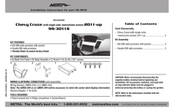
Installation instructions for part 99-7898
See application list inside
Acura/Honda/Isuzu 1990-2006
99-7898
AT-807HD, IBR-807HD, CF-807HD, AW-807HD
REV. 10/15/2015 INST-99-7898
KIT FEATURES
• DIN radio provision with pocket
• ISO DIN radio provision with pocket
• Pocket holds (2) jewel cases
WIRING & ANTENNA CONNECTIONS (sold separately)
Wiring Harness:
• 70-1720
•70-1721
Antenna Adapter:
•Not required
TOOLS REQUIRED
• Phillips screwdriver • Cutting tool
KIT COMPONENTS
• A) Radio housing • B) Faceplate • C) ISO trimming • D) ISO spacers • E) ISO brackets
• F) Mounting brackets • G) Rear support bracket (R1) • H) Rear support bracket (R2)
• I) (2) #8 x 3/4” Phillips screws • J) (6) #8 x 3/8” Phillips screws
A
B
C
H
I
J
D
METRA. The World’s best kits.™
E
F
G
metraonline.com
CAUTION! Metra recommends disconnecting the negative battery terminal before beginning any installation, unless the vehicle
manufacturer recommends against so. Please check with your local
Dealership for more information. All accessories, switches, climate
controls panels, and especially air bag indicator lights must be connected before reconnecting the battery or cycling the ignition. Also,
do not remove the factory radio with the key in the on position, or the
vehicle running. It would be best to remove the key from the ignition
and then wait a few seconds before removing the factory radio.
© COPYRIGHT 2004-2015 METRA ELECTRONICS CORPORATION
99-7898
Applications
Table of Contents
Acura
Honda
Dash Disassembly
- Honda Odyssey 1995-1998................................ 11
CL ................................... 1997-1999
Accord.............................. 1990-2002
- Acura CL 1997-1999........................................... 3
- Honda Odyssey 1999-2004 (without NAV).......... 11
Integra.............................. 1990-2001
Civic................................. 1996-2000
- Acura Integra 1990-1993..................................... 3
- Honda Prelude 1989-1991................................. 12
Legend............................. 1990-1995
Civic SE............................ 2005 (only)
RSX.................................. 2002-2006
CRV.................................. 1997-2006
TL..................................... 1996-1998
Odyssey............................ 1995-1998
Vigor................................. 1992-1994
Odyssey (without NAV)...... 1999-2004
Prelude............................. 1989-2001
Isuzu
Oasis................................ 1996-1999
- Acura Integra 1994-2001..................................3-4
- Honda Prelude 1992-1996................................. 12
- Acura Legend 1990-1995.................................... 4
- Honda Prelude 1997-2001................................. 13
- Acura RSX 2002-2006......................................... 5
- Isuzu Oasis 1996-1999...................................... 11
- Acura TL 1996-1998............................................ 5
- Acura Vigor 1992-1994........................................ 6
Kit Assembly
- Honda Accord 1990-1993.................................... 6
- DIN radio provision
(Honda Civic 1996-1998 only).......................... 13
- Honda Accord 1994-1997.................................... 7
- Honda Accord 1998-2002.................................... 7
- Honda Civic 1996-1998....................................... 8
- Honda Civic 1999-2000....................................8-9
- Honda Civic SE 2005 (only)................................... 9
- Honda CRV 1997-2001...................................... 10
- Honda CRV 2002-2006...................................... 10
2
- DIN radio provision with pocket.......................... 14
- ISO DIN radio provision with pocket.................... 15
99-7898
Dash Disassembly
Acura Integra 1990-1993
Acura CL 1997-1999
1. Unclip the radio trim
bezel and disconnect
the clock and climate control wiring.
(Figure A)
2. Remove (2) 8mm hex head screws
securing the factory
radio and disconnect the
wiring.
(Figure A)
3. Cut and remove all
of the mounting clips
on the radio housing
EXCEPT clips “A” and
“A”
“H” (the clips can
be identified by the
stamped letter on the
back of the housing,
near each clip).
“H”
(Figure B)
“H”
4. Mount the rear support
bracket (R1) to the back
of the radio housing with (Figure B)
(2) #8 x 3/8” Phillips pan
head screws supplied. (Figure B)
Continue to kit assembly
1. Remove (3) screws
from each side of the
center console and
remove the console.
1. Remove the cover cap located under the
emergency brake and remove (2) screws exposed.
2. Remove (2) screws from the rear corners of the
lower dash trim bezel and remove.
3. Remove the ashtray and (2) screws exposed.
4. Unsnap the ashtray housing and disconnect the
cigarette lighter harness.
5. Remove the gear shifter knob and unsnap the
shifter trim.
Continue on next page
2. Remove (2) screws
securing the factory
radio to the sub-dash
support bracket. Slide
the radio/pocket
assembly out and
(Figure A)
disconnect the wiring.
(Figure A)
“C”
3. Cut and remove all
of the mounting clips
on the radio housing
EXCEPT clips “C” and
“H” (the clips can
be identified by the
stamped letter on the
back of the housing,
near each clip).
(Figure B)
Acura Integra 1994-2001
“C”
“H”
“H”
(Figure B)
Continue to kit assembly
3
(Figure A)
99-7898
Dash Disassembly
Acura Legend 1990-1995
Acura Integra 1994-2001
6. Remove (2) screws below the radio opening and
remove the upper dash trim bezel. (Figure A)
7. Remove (2) 8mm screws securing the factory radio
and disconnect the wiring.
8. Cut and remove all of the mounting clips on the
radio housing EXCEPT clips “C” and “H” (the clips
can be identified by the stamped letter on the back
of the housing, near each clip). (Figure B)
Continue to kit assembly
1. Remove (2) screws below the ashtray. (Figure A)
2. Unclip the dash trim bezel.
3. Disconnect the cigarette lighter wiring and remove the bezel.
4. Remove (2) bolts securing the rear of the factory radio and
disconnect the wiring.
5. Cut and remove all of the mounting clips on the radio housing
EXCEPT clips “E” and “J” (the clips can be identified by the
stamped letter near each clip). (Figure B)
Continue to kit assembly
(Figure A)
“C”
“E”
“C”
“H”
“E”
“J”
“H”
“J”
(Figure B)
(Figure B)
4
99-7898
Dash Disassembly
Acura TL 1996-1998
Acura RSX 2002-2006 (except “S” model)
1. Unclip the lower dash panel (containing the power outlet) and remove the panel.
2. Reach into the opening and remove (2) Phillips screws from the base of the factory radio.
3. Slide the factory radio (with bracket assembly) from the dash and disconnect
the wiring. (Figure A)
4. Remove (4) Phillips screws securing the factory radio to the bracket assembly
and remove the radio (if a factory pocket is present, remove (4) Phillips screws
securing the pocket to the bracket assembly and remove). (Figure A)
5. Cut and remove the all mounting clips on the radio housing EXCEPT clips “J”
(the clips can be identified by the stamped letter near each clip). (Figure B)
6. Mount the rear support bracket (R2) to the back of the radio housing with (2) #8
x 3/8” Phillips pan head screws supplied.
Continue to kit assembly
1. Using a small screwdriver, unclip the
perimeter of the radio trim bezel.
(Figure A)
2. Disconnect the climate control and rear defroster wiring and
remove the bezel.
3. Remove (4) Phillips screws securing
the factory radio/trim bezel
assembly. (Figure A)
4. Loosen (2) Phillips screws securing
the back of the radio to the metal
housing and slide the radio out (it is
not necessary to remove the screws
securing the metal).
5. Disconnect the wiring.
6. Cut and remove all of the mounting
clips on the radio housing EXCEPT
clips “B” and “K” (the clips can be
identified by the stamped letter near
each clip). (Figure B)
Continue to kit assembly
“B”
“B”
“J”
“K”
“J”
(Figure A)
(Figure B)
(Figure A)
5
(Figure B)
“K”
99-7898
Dash Disassembly
Acura Vigor 1992-1994
1. Remove the access cap from the
climate control cluster and (1) screw
exposed. (Figure A)
2. Unclip the cluster and remove (2)
screws exposed. (Figure A)
3. Remove the ashtray and (2) Phillips
screws exposed.
4. Remove the cover caps from each
front corner of the center console
and the screws exposed.
5. Open the storage compartment,
lift up the carpet and remove (2)
screws exposed.
Honda Accord 1990-1993
6. Lift up on the center console and
remove. Unclip the radio trim bezel
and disconnect the wiring.
1. Remove (4) screws from the lower
portion of the center console.
(Figure A)
7. Remove (2) bolts from the back of the
factory radio and disconnect the wiring.
2. Remove the gear shifter knob and
lift the console out. Remove the
ashtray and ashtray bracket.
8. Cut and remove all of the mounting
clips on the radio housing EXCEPT
clips “A” and “H” (the clips can be
identified by the stamped letter on
the back of the housing, near each
clip). (Figure B)
3. Remove (2) screws from the
bottom of the radio support, slide the radio out and disconnect
the wiring.
Continue to kit assembly
4. Cut and remove all of the mounting
clips on the radio housing EXCEPT
clips “C” and “H” (the clips can be
identified by the stamped letter on
the back of the housing, near each
clip). (Figure B)
“A”
“A”
“H”
Continue to kit assembly
(Figure A)
“C”
“C”
“H”
“H”
“H”
(Figure A)
(Figure B)
(Figure B)
6
99-7898
Dash Disassembly
Honda Accord 1998-2002
Honda Accord 1994-1997
1. Remove the ashtray and (1) 3/4” #8
Phillips screw exposed. Open the
storage compartment and remove
(2) #8 Phillips screws exposed.
2. Remove the cup holder tray and (3)
#8 Phillips screws inside.
3. Lift the center console out and
remove (2) Phillips screws exposed
at the base of the dash trim bezel.
4. Unclip the bezel and remove.
5. Remove (2) hex head screws
securing the factory radio and
1. Unsnap the clock panel, disconnect
the wiring and remove. (Figure A)
2. Remove (1) Phillips screw exposed
in the clock cavity.
3. Remove (2) Phillips screws below
the factory radio.
4. Unclip the radio trim bezel and
disconnect the wiring. (Figure A)
5. Remove (4) Phillips screws securing
the factory radio assembly and
disconnect the wiring.
6. Remove (2) screws securing the
disconnect the wiring. (Figure A)
6. Cut and remove all of the mounting
clips on the radio housing EXCEPT
clips “A” and “H” (the clips can be
identified by the stamped letter on
the back of the housing, near each
clip). (Figure B)
7. Mount the rear support bracket (R1)
to the back of the radio housing
with (2) #8 x 3/8” Phillips pan head
screws supplied.
Continue to kit assembly
factory pocket to the assembly.
7. Cut and remove the mounting clips
from the radio housing.
8. From the mounting brackets cut and
remove tabs “B” (the clips can be
identified by the stamped letter on
the back of the housing, near each
clip). (Figure B)
9. Secure the brackets to the housing with (4) #8 x 3/8” Phillips
pan head screws.
Continue to kit assembly
“B”
“A”
“H”
“H”
(Figure A)
(Figure A)
(Figure B)
7
(Figure B)
99-7898
Dash Disassembly
Honda Civic 1996-1998
1. Remove (2) Phillips screws from the bottom edge of the glove box door and
remove the door.
1. Remove (2) Phillips screws
from the bottom edge of
the glove box door and
remove the door.
2. Remove (3) Phillips screws from the lower
steering column panel.
2. Remove (3) Phillips screws
from the lower steering
column panel.
3. Pull straight down on the lower steering
column panel and remove the panel.
4. Remove (2) Phillips screws under the
climate control panel. (Figure A)
Honda Civic 1999-2000
3. Pull straight down on the lower steering
column panel and remove
the panel.
(Figure A)
5. Remove (4) Phillips screws from the lower
dash location.
6. Remove (2) 8mm hex head screws securing
the bottom-rear of the factory radio and
disconnect the wiring.
4. Remove (2) Phillips screws
under the climate controls.
5. Remove (4) Phillips screws
from the lower dash
location. (Figure A)
6. Remove (4) Phillips screws
securing the bottom of
the dash trim bezel/radio
assembly and pull the
assembly out as far as
possible.
“B”
7. Locate the faceplate. (Figure B)
“B”
Continue to kit assembly
(Figure B)
“H”
“H”
8
(Figure A)
(Figure B)
99-7898
Dash Disassembly
Honda Civic
1999-2000
7. Cut the zip ties securing
the radio and climate
control wires, slide the
dash trim bezel/radio
assembly from the dash
cavity and disconnect the
wiring.
Honda Civic SE 2005 (only)
1. Unsnap and remove the trim ring from
around floor shifter.
side) and remove with power outlet assembly.
2. Unsnap and remove larger trim around
floor console shifter.
5. Remove (2) Phillips screws from under
radio assembly, facing up. (Figure A)
3. Remove (2) Phillips screws from in
between cup holder and shifter. (Figure A)
6. Remove (3) screws securing the climate
control pod to the back of the dash trim
bezel and remove the pod. (Figure B)
4. Unsnap sides of console (2 snaps per
7. Remove (4) Phillips screws from each
8. Cut and remove all of the
mounting clips on the
radio housing EXCEPT
clips “B” and “H” (the
clips can be identified by
the stamped letter on the
back of the housing, near
each clip).
(Figure B)
side securing the factory head radio to the
bracket assembly and remove the radio.
8. Cut and remove all mounting clips on
the radio housing, EXCEPT clips “B”
and “H” (the clips can be identified by
the stamped letter on the back of the
housing, near each clip). (Figure C)
Continue to kit assembly
“B”
“B”
“H”
Continue to kit assembly
“H”
(Figure A)
(Figure B)
9
(Figure C)
99-7898
Dash Disassembly
Honda CR-V 1997-2001
1. Open the glove box, squeeze the retaining clips and remove the stoppers.
2. Lower the glove box and remove (2)
Phillips screws from the left edge.
3. Remove (2) Phillips screws from the lower steering column
panel and remove.
4. Unclip the lower console cover (below
the ashtray and pocket) and remove.
5. Remove (2) Phillips screws from the
base of the center console, open
the console pocket and remove the
(4) outer screws exposed.
Honda CR-V 2002-2006
6. Unclip the center console and remove.
7. Remove (2) Phillips screws securing
the radio trim bezel, disconnect the
wiring, and remove the trim bezel/
radio assembly. (Figure A)
8. Remove (4) Phillips screws securing
the radio to the bezel and remove.
9. Cut and remove all of the mounting
clips on the radio housing EXCEPT
clips “B” and “H” (the clips can be
identified by the stamped letter on
the back of the housing, near each
clip). (Figure B)
Continue to kit assembly
1. Remove (2) Phillips screws from the bottom edge of the radio
trim bezel. (Figure A)
2. Unclip the trim bezel and remove.
3. Remove (4) Phillips screws securing the factory radio and
disconnect the wiring.
4. Cut and remove all of the mounting
clips on the radio housing EXCEPT
clips “A” and “H” (the clips can be
identified by the stamped letter on
the back of the housing, near each
clip). (Figure B)
“B”
“B”
(Figure A)
“A”
“A”
Continue to kit assembly
“H”
“H”
“H”
(Figure B)
“H”
(Figure A)
(Figure B)
10
99-7898
Dash Disassembly
Honda Odyssey 1995-1998
Honda Odyssey 1999-2004 (without NAV)
Isuzu Oasis 1996-1999
1. Lower the glove box assembly.
2. Remove (2) Phillips screws exposed
on the right side of the underdash.
3. Remove (2) Phillips screws from the
driver’s side knee bolster and (1)
Phillips screw in the coin pocket.
4. Remove (5) Phillips screws from the
underdash panel and remove the
panel. (Figure A)
5. Remove (4) Phillips screws from the
cupholder assembly and remove.
1. Unclip the radio trim bezel
(including the climate control panel
and remove). (Figure A)
6. Remove (2) Phillips screws securing the factory radio and
disconnect the wiring.
2. Remove (4) Phillips screws securing the factory radio and
disconnect the wiring.
7. Cut and remove all of the mounting
clips on the radio housing EXCEPT clips
“D” and “H” (the clips can be identified
by the stamped letter on the back of
the housing, near each clip). (Figure B)
3. Cut and remove the mounting clips
from the radio housing.
4. From the mounting brackets cut
and remove tabs “A” (the clips can
be identified by the stamped letter
on the back of the housing, near
each clip). (Figure B)
Continue to kit assembly
“A”
5. Secure the brackets to the housing
with (4) #8 x 3/8” Phillips pan head
screws. (Figure B)
“D”
“D”
“H”
Continue to kit assembly
(Figure B)
“H”
(Figure A)
(Figure A)
(Figure B)
11
99-7898
Dash Disassembly
Honda Prelude 1989-1991
Honda Prelude 1992-1996
1. Remove (2) Phillips screws located below the climate controls.
(Figure A)
1. Remove (2) screws from the top of
the console trim bezel.
2. Slide the front seats back and
remove (4) Phillips screws from
each side of the bezel. (Figure A)
2. Remove (1) Phillips screw from
each side of the dash console and
(2) Phillips screws from each side
of the floor console. (Figure A)
3. Remove the plastic dummy cap
from the end of the dash console
and (2) Phillips screws exposed.
(Figure A)
4. Pull the floor console out and
gently remove the dash console.
3. Pull up on the console trim bezel and remove.
“C”
5. Remove (4) screws from the radio
trim bezel, remove the factory
radio assembly and disconnect the
wiring. (Figure A)
“A”
“A”
5. Remove (6) Phillips screws securing the factory radio and
disconnect the wiring.
6. Cut and remove all of the mounting
clips on the radio housing EXCEPT
clips “A” and “C” (the clips can be
identified by the stamped letter on
the back of the housing, near each
clip). (Figure B)
4. Using an angled screwdriver,
remove (2) screws securing the
gear shifter bracket to the bezel.
(Figure A)
“C”
6. Cut and remove all of the mounting
clips on the radio housing EXCEPT
clips “F” and “H” (the clips can be
identified by the stamped letter on
the back of the housing, near each
clip). (Figure B)
(Figure B)
Continue to kit assembly
12
Continue to kit assembly
(Figure A)
“F”
“H”
“H”
(Figure B)
“F”
99-7898
Dash Disassembly
Honda Prelude 1997-2001
Kit Assembly
DIN radio provision
1. Using a panel removal tool, unclip
the radio trim bezel and remove
(some force may be required). (Figure A)
Honda Civic 1996-1998:
1. Remove the metal DIN sleeve from
the aftermarket radio.
2. Position the faceplate in the radio
opening by inserting the locating
pins on the housing into the holes in
the sub-dash. (Figure A)
Note: if a radio dummy plate was
removed during the dash disassembly,
cut and remove the locating pins on
the radio housing.
3. Slide the sleeve into the kit and
2. Remove (4) Phillips screws
securing the factory radio/bracket
housing assembly and disconnect
the wiring.
3. Remove (4) Phillips screws
securing the factory radio to the
bracket housing and remove.
4. Cut and remove all of the mounting
clips on the radio housing EXCEPT
clips “A” and “G” (the clips can be
identified by the stamped letter on
the back of the housing, near each
clip). (Figure B)
(Figure A)
“A”
“A”
“G”
“G”
Continue to kit assembly
(Figure B)
(Figure A)
13
secure by bending the metal locking
tabs down. (Figure A)
4. Slide the radio into the sleeve until
secure. (Figure A)
5. Locate the factory wiring harness and
antenna connector in the dash. Metra
recommends using the proper mating
adapter from Metra or AXXESS. Reconnect the negative battery terminal
and test the radio for proper operation.
6. Reassemble the dash in reverse
order of disassembly.
99-7898
Kit Assembly
DIN radio provision with pocket
Accord 1990-1997, Civic 1999-2000,
CL 1997-1999, CRV 1997-2002,
Integra 1990-2001, Legend 19901996, Oasis 1996-1999, Odyssey
1995-1998, Prelude 1989-2001, RSX
2002-2006, TL 1996-1998, Vigor
1992-1994:
1. Remove the metal DIN sleeve from
the aftermarket radio.
2. Slide the sleeve into the radio
housing and secure by bending the
metal locking tabs down. (Figure A)
3. Slide the radio into the sleeve until
secure. (Figure A)
4. Locate the factory wiring harness
and antenna connector in the dash.
Metra recommends using the proper
mating adapter from Metra or
AXXESS. Re-connect the negative
battery terminal and test the radio
for proper operation.
5. Reassemble the dash in reverse
order of disassembly.
Accord 1998-2002, Odyssey
1999-2004:
**For Honda Accord 1994-1997 and CL 1997-1999:
Mount the rear support bracket to
the rear support provision with (2)
bolts previously removed in the dash
disassembly.
**For Honda RSX 2002-2006:
Mount the rear support bracket to
the rear support provision with (2)
#8 x ¾” Phillips screws included.
1. Remove the metal DIN sleeve from
the aftermarket radio.
2. Slide the sleeve into the radio
housing and secure by bending the
metal locking tabs down. (Figure A)
3. Slide the radio into the sleeve until
secure. (Figure A)
4. Locate the factory wiring harness
and antenna connector in the
dash. Metra recommends using
the proper mating adapter from
Metra or AXXESS. Re-connect the
negative battery terminal and test
the radio for proper operation.
5. Reassemble the dash in reverse
order of disassembly.
(Figure A)
14
(Figure A)
99-7898
Kit Assembly
ISO DIN radio provision with pocket
Accord 1990-1997, Civic 1999-2000, CL 1997-1999, CRV 1997-2002, Integra 19902001, Legend 1990-1996, Oasis 1996-1999,
Odyssey 1995-1998, Prelude 1989-2001, RSX
2002-2006, TL 1996-1998, Vigor 1992-1994:
1. Snap the ISO trim ring into the radio
housing. (Figure A)
2. Mount the ISO brackets to the radio housing
with (4) #8 x 3/8” screws supplied. (Figure A)
3. Remove the metal DIN sleeve and trim ring
from the aftermarket radio.
4. Slide the radio into the completed assembly,
align the holes in the radio with the holes
in the brackets, and then mount with the
screws supplied with the radio. (Figure A)
5. Locate the factory wiring harness and
antenna connector in the dash. Metra
recommends using the proper mating
adapter from Metra or AXXESS. Re-connect
the negative battery terminal and test the
radio for proper operation.
6. Reassemble the dash in reverse order of
disassembly.
**For Honda Accord 1994-1997 and CL
1997-1999:
Mount the rear support bracket to the rear
support provision with (2) bolts previously
removed in the dash disassembly.
**For Honda RSX 2002-2006:
Mount the rear support bracket to the rear
support provision with (2) #8 x ¾” Phillips
screws included.
Accord 1998-2002, and then mount with the
Odyssey 1999-2004:
screws supplied with the
radio. (Figure A)
1. Attach the ISO spacers onto
the sides of the radio brackets, 4. Locate the factory wiring
and then snap the ISO trim ring
harness and antenna connector
into the radio housing. (Figure A)
in the dash. Metra recommends
using the proper mating adapter
2. Remove the metal DIN
from Metra or AXXESS. Resleeve and trim ring from the
connect the negative battery
aftermarket radio.
terminal and test the radio for
3. Slide the radio into the
proper operation.
completed assembly, align
5.
Reassemble
the dash in
the holes in the radio with
reverse order of disassembly.
the holes in the ISO spacers,
(Figure A)
(Figure A)
15
Installation instructions for part 99-7898
IMPORTANT
If you are having difficulties with the
installation of this product, please call our
Tech Support line at 1-800-253-TECH.
Before doing so, look over the instructions a
second time, and make sure the installation
was performed exactly as the instructions
are stated. Please have the vehicle apart
and ready to perform troubleshooting steps
before calling.
KNOWLEDGE IS POWER
REV. 10/15/2015 INST-99-7898
Enhance your installation and fabrication skills by
enrolling in the most recognized and respected
mobile electronics school in our industry.
Log onto www.installerinstitute.com or call
800-354-6782 for more information and take steps
toward a better tomorrow.
Metra recommends MECP
certified technicians
METRA. The World’s best kits.™
metraonline.com
© COPYRIGHT 2004-2015 METRA ELECTRONICS CORPORATION
Instrucciones de instalación para la pieza 99-7898
Ver lista de aplicaciones en el interior
Acura/Honda/Isuzu 1990-2006
99-7898
AT-807HD, IBR-807HD, CF-807HD, AW-807HD
REV. 10/15/2015 INST-99-7898
CARACTERÍSTICAS DEL KIT
• Provisión de radio DIN con cavidad
• Provisión de radio ISO DIN con cavidad
• Cavidad tiene (2) estuches
CABLEADO Y CONEXIONES DE ANTENA
(se venden por separado)
Arnés de cableado:
• 70-1720
•70-1721
Adaptador de antena:
•No se requiere
HERRAMIENTAS REQUERIDAS
• Destornillador Phillips • Herramienta de corte
COMPONENTES DEL KIT
• A) Carcasa del radio • B) Placa frontal • C) Placa de moldura del radio • D) Espaciadores ISO
• E) Soportes ISO • F) Soportes de montaje • G) Soporte de apoyo (R1) • H) Soporte de apoyo (R2)
• I) (2) Tornillos Phillips #8 x 3/4” • J) (6) Tornillos Phillips #8 x 3/8”
A
B
C
H
I
J
D
METRA. The World’s best kits.™
E
F
G
metraonline.com
¡PRECAUCIÓN! Meta recomienda desconectar la terminal negativa
de la batería antes de iniciar cualquier instalación, a menos que el
fabricante del vehículo recomiende lo contrario. Verifique con su
concesionario local si existe más información. Todos los accesorios,
interruptores, paneles de controles de clima y especialmente las luces del indicador de las bolsas de aire deben estar conectados antes
de reconectar la batería o ciclar la ignición. Además, no quite el radio
de fábrica con la llave en la posición de encendido ni con el vehículo
funcionando. Sería mejor retirar la llave de la ignición y esperar unos
cuantos segundos antes de quitar el radio de fábrica.
© COPYRIGHT 2004-2015 METRA ELECTRONICS CORPORATION
99-7898
Aplicaciones
Indice
Acura
Honda
Desmontaje tablero
- Honda Odyssey 1995-1998................................ 11
CL ................................... 1997-1999
Accord.............................. 1990-2002
- Acura CL 1997-1999........................................... 3
- Honda Odyssey 1999-2004 (sin NAV)................. 11
Integra.............................. 1990-2001
Civic................................. 1996-2000
- Acura Integra 1990-1993..................................... 3
- Honda Prelude 1989-1991................................. 12
Legend............................. 1990-1995
Civic SE..................... 2005 (solamente)
RSX.................................. 2002-2006
CRV.................................. 1997-2006
TL..................................... 1996-1998
Odyssey............................ 1995-1998
Vigor................................. 1992-1994
Odyssey (sin NAV)............. 1999-2004
Prelude............................. 1989-2001
Isuzu
Oasis................................ 1996-1999
- Acura Integra 1994-2001..................................3-4
- Honda Prelude 1992-1996................................. 12
- Acura Legend 1990-1995.................................... 4
- Honda Prelude 1997-2001................................. 13
- Acura RSX 2002-2006......................................... 5
- Isuzu Oasis 1996-1999...................................... 11
- Acura TL 1996-1998............................................ 5
- Acura Vigor 1992-1994........................................ 6
Ensamble del kit
- Honda Accord 1990-1993.................................... 6
- Provisión de radio DIN
(Honda Civic 1996-1998 solamente)................. 13
- Honda Accord 1994-1997.................................... 7
- Honda Accord 1998-2002.................................... 7
- Honda Civic 1996-1998....................................... 8
- Honda Civic 1999-2000....................................8-9
- Honda Civic SE 2005 (solamente)........................... 9
- Honda CRV 1997-2001...................................... 10
- Honda CRV 2002-2006...................................... 10
2
- Provisión de radio DIN con cavidad.................... 14
- Provisión de radio ISO DIN con cavidad.............. 15
99-7898
Acura CL 1997-1999
1. Desenganche el bisel de
la moldura del radio y
desconecte el cableado
del reloj y del control del
clima. (Figura A)
2. Quite los (2) tornillos de
cabeza hexagonal de 8
mm que sujetan el radio
de fábrica y desconecte
el cableado.
(Figura A)
3. Corte y quite todos los
ganchos de montaje
“A”
de la carcasa del radio
EXCEPTO los ganchos
“A” y “H” (los ganchos
pueden identificarse por
el estampada carta parte
posterior de la carcasa, “H”
cerca de cada clip).
“H”
(Figura B)
(Figura B)
4. Monte el soporte de
apoyo trasero (R1) en la
parte posterior la carcasa del radio (b) con los
(2) tornillos Phillips de cabeza troncocónica #8 x
3/8” suministrados. (Figura B)
Continúe con el ensamble del kit
Desmontaje tablero
Acura Integra 1990-1993
1. Quite los (3) tornillos
a cada lado de la
consola central y quite
la consola.
Acura Integra 1994-2001
1. Quite la tapa de la cubierta localizada debajo del freno
de emergencia y quite los (2) tornillos expuestos.
2. Quite los (2) tornillos de las esquinas traseras del
bisel de la moldura del tablero inferior y quite.
3. Quite el cenicero y los (2) tornillos expuestos.
4. Suelte a presión la carcasa del cenicero y
desconecte el arnés del encendedor.
5. Retire la perilla de la palanca de velocidades y
suelte a presión la moldura de la palanca
Continúa en las siguiente página
2. Quite los (2) tornillos
que sujetan el radio de
fábrica al soporte de
apoyo del sub tablero.
Deslice el ensamble
de radio/cavidad hacia (Figura A)
afuera y desconecte el
cableado. (Figura A)
“C”
3. Corte y quite todos los
ganchos de montaje
de la carcasa del radio
EXCEPTO los ganchos
“C” y “H” (los ganchos
“H”
pueden identificarse
por el estampada
carta parte posterior
de la carcasa, cerca
(Figura B)
de cada clip).
(Figura B)
Continúe con el ensamble del kit
3
“C”
“H”
(Figura A)
99-7898
Desmontaje tablero
Acura Legend 1990-1995
Acura Integra 1994-2001
6. Quite los (2) tornillos debajo de la apertura del
radio y quite el bisel de la moldura del tablero
superior. (Figura A)
1. Quite los (2) tornillos de debajo del cenicero. (Figura A)
7. Quite los (2) tornillos de 8 mm que sujetan el radio
de fábrica y desconecte el cableado.
3. Desconecte el cableado del encendedor y retire el bisel.
8. Corte y quite todos los ganchos de montaje de la carcasa
del radio EXCEPTO los ganchos “C” y “H” (los ganchos
pueden identificarse por el estampada carta parte
posterior de la carcasa, cerca de cada clip). (Figura B)
Continúe con el ensamble del kit
2. Desenganche el bisel de la moldura del tablero.
4. Retire los (2) pernos que sujetan la parte trasera del radio de
fábrica y desconecte el cableado.
5. Corte y quite todos los ganchos de montaje de la carcasa del
radio EXCEPTO los ganchos “E” y “J” (los ganchos pueden
identificarse por el estampada carta parte posterior de la carcasa,
cerca de cada clip). (Figura B)
(Figura A)
Continúe con el ensamble del kit
“C”
“E”
“C”
“H”
“E”
“J”
“H”
“J”
(Figura B)
(Figura B)
4
99-7898
Desmontaje tablero
Acura TL 1996-1998
Acura RSX 2002-2006 (excepto el modelo “S”)
1. Desenganche el tablero central inferior (que contiene el tomacorriente) y quite el panel.
2. Deslice en la apertura y quite los (2) tornillos Phillips de la base del radio de fábrica.
3. Deslice el radio de fábrica (con el ensamble de soporte) del tablero y desconecte
el cableado. (Figura A)
4. Quite los (4) tornillos Phillips que sujetan el radio de fábrica al ensamble del
soporte y quite el radio (si hay cavidad de fábrica presente, quite los (4) tornillos
Phillips que sujetan la cavidad al ensamble del soporte y quítelo). (Figura A)
5. Corte y quite todos los ganchos de montaje de la carcasa del radio EXCEPTO
los ganchos “J” (los ganchos pueden identificarse por el estampada carta parte
posterior de la carcasa, cerca de cada clip). (Figura B)
6. Monte el soporte de apoyo trasero (R2) en la parte posterior la carcasa del radio
con los (2) tornillos Phillips de cabeza troncocónica #8 x 3/8” suministrados.
Continúe con el ensamble del kit
1. Usando un destornillador pequeño,
desenganche el perímetro del bisel
de la moldura del radio. (Figura A)
2. Desconecte el cableado del control
de clima y del desempañador
trasero y retire el bisel.
3. Quite los (4) tornillos Phillips que
sujetan el ensamble del radio de
fábrica/bisel de la moldura. (Figura A)
4. Afloje los (2) tornillos Phillips que
sujetan la parte posterior del radio a
la carcasa metálica y deslice el radio
hacia afuera (no es necesario retirar
los tornillos que sujetan el metal).
5. Desconecte el cableado.
6. Corte y quite todos los ganchos de
montaje de la carcasa del radio
EXCEPTO los ganchos “B” y “K” (los
ganchos pueden identificarse por el
estampada carta parte posterior de la
carcasa, cerca de cada clip). (Figura B)
Continúe con el ensamble del kit
“B”
“B”
“J”
“K”
“J”
(Figura A)
(Figura B)
(Figura A)
5
(Figura B)
“K”
99-7898
Desmontaje tablero
Acura Vigor 1992-1994
Honda Accord 1990-1993
1. Retire la tapa de acceso del
conjunto del control del clima y (1)
tornillos expuesto. (Figura A)
2. Desenganche el conjunto y quite los
(2) tornillos expuestos. (Figura A)
3. Quite el cenicero y los (2) tornillos
Phillips expuestos.
4. Quite las tapas de la cubierta de
cada esquina delantera de la consola
central y los tornillos expuestos.
5. Abra el compartimiento de
almacenamiento, levante la alfombra
y quite los (2) tornillos expuestos.
6. Levante la consola central y retire.
Desenganche el bisel de la moldura
del radio y desconecte el cableado.
7. Retire los (2) pernos de la parte trasera
del radio de fábrica y desconecte el
cableado.
8. Corte y quite todos los ganchos de
montaje de la carcasa del radio
EXCEPTO los ganchos “A” y “H” (los
ganchos pueden identificarse por el
estampada carta parte posterior de la
carcasa, cerca de cada clip). (Figura B)
1. Quite los (4) tornillos de la porción
inferior de la consola central.
(Figura A)
2. Retire la perilla de la palanca de
velocidades y levante la consola
para sacarla. Retire el cenicero y el
soporte del cenicero.
3. Quite los (2) tornillos de la parte
inferior del radio de fábrica, deslice
el radio hacia afuera y desconecte
el cableado.
Continúe con el ensamble del kit
4. Corte y quite todos los ganchos de
montaje de la carcasa del radio
EXCEPTO los ganchos “C” y “H”
(los ganchos pueden identificarse
por el estampada carta parte
posterior de la carcasa, cerca de
cada clip). (Figura B)
“A”
“A”
“H”
“H”
(Figura A)
(Figura A)
“C”
“C”
“H”
“H”
Continúe con el ensamble del kit
(Figura B)
(Figura B)
6
99-7898
Desmontaje tablero
Honda Accord 1998-2002
Honda Accord 1994-1997
1. Retire el cenicero y (1) tornillo Phillips #8
de 3/4” expuesto. Abra el compartimiento
de almacenamiento y quite los (2)
tornillos Phillips #8 expuestos.
2. Quite la charola del portavasos y los
(3) tornillos Phillips #8 del interior.
3. Levante la consola central y quite los
(2) tornillos Phillips expuestos en la
base del bisel de la moldura del radio.
4. Desenganche el bisel y quite.
5. Quite los (2) tornillos de cabeza
hexagonal que sujetan el radio de fábrica
y desconecte el cableado. (Figura A)
1. Suelte a presión el panel del radio,
desconecte el cableado y retire.
(Figura A)
2. Retire (1) tornillo Phillips expuesto
en la cavidad del reloj.
3. Quite los (2) tornillos Phillips debajo
del radio de fábrica.
4. Desenganche el bisel de la moldura
del radio y desconecte el cableado.
(Figura A)
5. Quite los (4) tornillos Phillips que
sujetan el ensamble del radio de
fábrica y desconecte el cableado.
6. Corte y quite todos los ganchos de
montaje de la carcasa del radio
EXCEPTO los ganchos “A” y “H” (los
ganchos pueden identificarse por
el estampada carta parte posterior
de la carcasa, cerca de cada clip).
(Figura B)
7. Monte el soporte de apoyo trasero
(R1) en la parte posterior la carcasa
del radio (b) con los (2) tornillos
Phillips de cabeza troncocónica #8 x
3/8” suministrados.
Continúe con el ensamble del kit
6. Quite los (2) tornillos que sujetan la
cavidad de fábrica al ensamble.
7. Corte y quite los ganchos de
montaje de la carcasa del radio.
8. A partir de los soportes de montaje
cortar y quitar las pestañas “B” (los
clips se pueden identificar por la letra
estampada en la parte posterior de la
vivienda, cerca de cada clip). (Figura B)
9. Sujete los soportes a la carcasa con
los (4) tornillos Phillips de cabeza
troncocónica #8 de 3/8” suministrados.
Continúe con el ensamble del kit
“B”
“A”
“H”
“H”
(Figura A)
(Figura A)
(Figura B)
7
(Figura B)
99-7898
Desmontaje tablero
Honda Civic 1996-1998
1. Quite los (2) tornillos Phillips del borde
inferior de la puerta de la guantera y
quite la puerta.
1. Quite los (2) tornillos
Phillips del borde inferior
de la puerta de la guantera
y quite la puerta.
2. Quite (3) tornillos Phillips del panel inferior
de la columna de dirección.
2. Quite (3) tornillos Phillips
del panel inferior de la
columna de dirección.
3. Jale en línea recta hacia abajo en el panel de la
columna de dirección inferior y quite el panel.
4. Quite (2) tornillos Phillips que están debajo
del panel de control de clima. (Figura A)
Honda Civic 1999-2000
3. Jale en línea recta hacia
abajo en el panel de la
columna de dirección
inferior y quite el panel.
(Figura A)
5. Quite (4) tornillos Phillips de la ubicación
inferior del tablero Quite (4) tornillos Phillips
de la ubicación inferior del tablero.
4. Quite los (2) tornillos
Phillips de abajo de los
controles del clima.
5. Quite (4) tornillos Phillips
de la ubicación inferior del
tablero. (Figura A)
6. Quite los (4) tornillos
Phillips que sujetan la
parte inferior del bisel de
la moldura del tablero/
ensamble de radio y jale
el ensamble para sacarlo
tanto como sea posible.
“B”
6. Quite los (2) tornillos de cabeza hexagonal de
8 mm que sujetan la parte trasera inferior del
radio de fábrica y desconecte el cableado.
“B”
7. Localice la placa frontal. (Figura B)
Continúe con el ensamble del kit
“H”
(Figura B)
“H”
(Figura A)
8
(Figura B)
99-7898
Desmontaje tablero
Honda Civic
1999-2000
7. Corte las corbatas que
sujetan los cables del radio y
del control de clima, deslice
el bisel de la moldura del
tablero/ensamble de radio
de la cavidad del tablero y
desconecte el cableado.
Honda Civic SE 2005 (solamente)
1. Suelte a presión y retire el anillo de la
moldura de alrededor de la palanca de
velocidades al piso.
4. Suelte a presión los lados de la consola,
(2 chasquidos por lado), y retire con el
ensamble del tomacorriente.
7. Quite (4) tornillos Phillips de cada
lado que sujetan el radio de fábrica al
ensamble del soporte y quite el radio.
2. Suelte a presión y retire la moldura de
alrededor de la palanca de velocidades
al piso.
5. Quite los (2) tornillos Phillips debajo del
ensamble del radio, orientados hacia
arriba. (Figura A)
3. Quite los (2) tornillos Phillips de entre el
portavasos y la palanca de velocidades.
(Figura A)
6. Quite (3) tornillos que sujetan el
alojamiento del control de clima a la
parte posterior del bisel de la moldura
del tablero y el alojamiento. (Figura B)
8. Corte y quite todos los ganchos de
montaje de la carcasa del radio
EXCEPTO los ganchos “B” y “H” (los
ganchos pueden identificarse por el
estampada carta parte posterior de la
carcasa, cerca de cada clip). (Figura C)
8. Corte y quite todos los
ganchos de montaje
de la carcasa del radio
EXCEPTO los ganchos
“B” y “H” (los ganchos
pueden identificarse por
el estampada carta parte
posterior de la carcasa,
cerca de cada clip).
(Figura B)
Continúe con el ensamble del kit
“B”
“B”
“H”
Continúe con el
ensamble del kit
“H”
(Figura A)
(Figura B)
9
(Figura C)
99-7898
Desmontaje tablero
Honda CR-V 1997-2001
Honda CR-V 2002-2006
1. Abra la guantera, apriete los ganchos
de retención y quite los topes.
2. Baje la guantera y quite (2) tornillos
Phillips de la orilla izquierda.
3. Quite los (2) tornillos Phillips del
panel de la columna de dirección
inferior y quite.
4. Desenganche la cubierta de la
consola inferior (debajo del cenicero y
la cavidad) y quite.
5. Quite (2) tornillos Phillips de la base
de la consola central, abra la cavidad
de la consola y quite los (4) tornillos
exteriores quedan expuestos.
1. Quite los (2) tornillos Phillips
del borde inferior del bisel de la
moldura del radio. (Figura A)
6. Unclip the center console and remove.
7. Remove (2) Phillips screws securing
the radio trim bezel, disconnect the
wiring, and remove the trim bezel/
radio assembly. (Figura A)
8. Remove (4) Phillips screws securing
the radio to the bezel and remove.
9. Corte y quite todos los ganchos de
montaje de la carcasa del radio
EXCEPTO los ganchos “B” y “H” (los
ganchos pueden identificarse por el
estampada carta parte posterior de la
carcasa, cerca de cada clip). (Figura B)
Continúe con el ensamble del kit
2. Desenganche el bisel de la
moldura y quítelo.
3. Remove (4) Phillips screws securing the factory radio and
disconnect the wiring.
4. Corte y quite todos los ganchos de
montaje de la carcasa del radio
EXCEPTO los ganchos “A” y “H”
(los ganchos pueden identificarse
por el estampada carta parte
posterior de la carcasa, cerca de
cada clip). (Figura B)
“B”
“B”
Continúe con el ensamble del kit
(Figura A)
“A”
“A”
“H”
“H”
“H”
(Figura B)
“H”
(Figura A)
(Figura B)
10
99-7898
Desmontaje tablero
Honda Odyssey 1995-1998
Honda Odyssey 1999-2004 (sin NAV)
Isuzu Oasis 1996-1999
1. Baje el ensamble de la guantera.
2. Quite los (2) tornillos Phillips expuestos
al lado derecho del sub tablero.
3. Quite los (2) tornillos Phillips del
protector de rodillas del lado del
conductor y (1) tornillo Phillips de la
cavidad de monedas.
4. Quite los (5) tornillos Phillips del
panel del sub tablero y quite el
panel. (Figura A)
1. Desenganche el bisel de la moldura
del radio (incluyendo el panel del
control de clima y quítelo. (Figura A)
5. Quite (4) tornillos Phillips del
ensamble del portavasos y quite.
6. Quite los (2) tornillos Phillips
que sujetan el radio de fábrica y
desconecte el cableado.
7. Corte y quite todos los ganchos de
montaje de la carcasa del radio
EXCEPTO los ganchos “D” y “H” (los
ganchos pueden identificarse por el
estampada carta parte posterior de la
carcasa, cerca de cada clip). (Figura B)
Continúe con el ensamble del kit
2. Quite los (4) tornillos Phillips
que sujetan el radio de fábrica y
desconecte el cableado.
3. Corte y quite los ganchos de
montaje de la carcasa del radio.
4. A partir de los soportes de montaje
cortar y quitar las pestañas “A”
(los clips se pueden identificar
por la letra estampada en la parte
posterior de la vivienda, cerca de
cada clip). (Figura B)
“D”
“A”
5. Sujete los soportes a la carcasa
con los (4) tornillos Phillips de
cabeza troncocónica #8 de 3/8”
suministrados. (Figura B)
“D”
“H”
“H”
(Figura A)
(Figura A)
(Figura B)
11
Continúe con el ensamble del kit
(Figura B)
99-7898
Desmontaje tablero
Honda Prelude 1989-1991
Honda Prelude 1992-1996
1. Quite los (2) tornillos Phillips
localizados debajo de los controles
del clima. (Figura A)
1. Quite los (2) tornillos de la parte
superior del bisel de la moldura de
la consola.
2. Quite (1) tornillo Phillips de cada
lado de la consola del tablero y (2)
tornillos Phillips de cada lado de la
consola del piso. (Figura A)
2. Deslice los asientos delanteros y
quite los (4) tornillos Phillips de
cada lado del bisel. (Figura A)
3. Quite la tapa falsa de plástico del
extremo de la consola del tablero y
los (2) tornillos Phillips que quedan
expuestos. (Figura A)
4. Jale la consola de piso hacia fuera
y retire suavemente la consola del
tablero.
3. Jale hacia arriba el bisel de la
moldura de la consola y quítelo.
“C”
“A”
5. Quite los (4) tornillos del bisel
de la moldura del radio, quite el
ensamble del radio de fábrica y
desconecte el cableado. (Figura A)
“A”
5. Quite los (6) tornillos Phillips
que sujetan el radio de fábrica y
desconecte el cableado.
6. Corte y quite todos los ganchos de
montaje de la carcasa del radio
EXCEPTO los ganchos “A” y “C” (los
ganchos pueden identificarse por el
estampada carta parte posterior de la
carcasa, cerca de cada clip). (Figura B)
4. Con el destornillador inclinado, quite
los (2) tornillos que sujetan el soporte
de la palanca de velocidades al bisel.
(Figura A)
“C”
6. Corte y quite todos los ganchos de
montaje de la carcasa del radio
EXCEPTO los ganchos “F” y “H”
(los ganchos pueden identificarse
por el estampada carta parte
posterior de la carcasa, cerca de
cada clip). (Figura B)
(Figura B)
Continúe con el ensamble del kit
12
Continúe con el ensamble del kit
(Figura A)
“F”
“H”
“H”
(Figura B)
“F”
99-7898
Desmontaje tablero
Honda Prelude 1997-2001
Ensamble del kit
Provisión de radio DIN
1. Con una herramienta de remoción
de paneles, desenganche el bisel
de la moldura del radio y quítelo
(puede requerirse un poco de
fuerza). (Figura A)
Honda Civic 1996-1998:
1. Quite la manga de metal DIN del
radio de mercado secundario.
2. Posicione la placa frontal en la
apertura del radio insertando las
clavijas localizadoras de la carcasa en
los orificios del sub tablero. (Figura A)
Nota: Si durante el desensamble del
tablero se quitó una placa simuladora
de radio, corte y quite las clavijas
localizadoras de la carcasa del radio.
3. Deslice la manga al kit y sujétela
doblando hacia abajo las pestañas
de metal. (Figura A)
2. Quite los (4) tornillos Phillips que
sujetan el ensamble del radio
de fábrica/carcasa del soporte y
desconecte el cableado.
3. Quite los (4) tornillos Phillips que
sujetan el radio de fábrica al
soporte y quítelo.
4. Corte y quite todos los ganchos de
montaje de la carcasa del radio
EXCEPTO los ganchos “A” y “G”
(los ganchos pueden identificarse
por el estampada carta parte
posterior de la carcasa, cerca de
cada clip). (Figura B)
Continúe con el ensamble del kit
(Figura A)
“A”
“A”
“G”
“G”
(Figura B)
(Figura A)
13
4. Slide the radio into the sleeve until
secure. (Figura A)
5. Localice el arnés de cableado de
fábrica y el conector de la antena en
el tablero y haga todas las conexiones
necesarias al radio. Metra recomienda
que use adaptadores adecuados
de acoplamiento de Metra y/o de
AXXESS. Vuelva a conectar la terminal
negativa de la batería y pruebe el
radio para verificar que funcione
correctamente..
6. Vuelva a armar el tablero al revés
de como lo desarmó.
99-7898
Ensamble del kit
Provisión de radio DIN con cavidad
Accord 1990-1997, Civic 1999-2000,
CL 1997-1999, CRV 1997-2002,
Integra 1990-2001, Legend 19901996, Oasis 1996-1999, Odyssey
1995-1998, Prelude 1989-2001, RSX
2002-2006, TL 1996-1998, Vigor
1992-1994:
1. Quite la manga de metal DIN y
el anillo de moldura del radio de
mercado secundario.
2. Deslice la manga en la carcasa del
radio y sujétela doblando hacia abajo
las pestañas de metal. (Figura A)
3. Deslice la radio en el manguito
hasta que quede firme. (Figura A)
4. Localice el arnés de cableado de
fábrica y el conector de la antena en
el tablero y haga todas las conexiones
necesarias al radio. Metra recomienda
que use adaptadores adecuados de
acoplamiento de Metra y/o de AXXESS.
Vuelva a conectar la terminal negativa
de la batería y pruebe el radio para
verificar que funcione correctamente.
5. Vuelva a armar el tablero al revés de
como lo desarmó.
Accord 1998-2002, Odyssey
1999-2004:
**Para Honda Accord 1994-1997 y CL 1997-1999:
Monte el soporte de apoyo trasero
en la provisión de soporte trasero
con los (2) pernos previamente
retirados durante el desensamble
del tablero.
**Para Honda RSX 2002-2006:
Monte el soporte de apoyo trasero
en la provisión del soporte trasero
con los (2) tornillos Phillips #8 x ¾”
incluidos.
1. Quite la manga de metal DIN del
radio de mercado secundario.
2. Deslice la manga en la carcasa del
radio y sujétela doblando hacia abajo
las pestañas de metal. (Figura A)
3. Deslice la radio en el manguito
hasta que quede firme. (Figura A)
4. Localice el arnés de cableado de
fábrica y el conector de la antena
en el tablero y haga todas las
conexiones necesarias al radio. Metra
recomienda que use adaptadores
adecuados de acoplamiento de Metra
y/o de AXXESS. Vuelva a conectar
la terminal negativa de la batería y
pruebe el radio para verificar que
funcione correctamente.
5. Vuelva a armar el tablero al revés
de como lo desarmó.
(Figura A)
14
(Figura A)
99-7898
Ensamble del kit
Provisión de radio ISO DIN con cavidad
Accord 1990-1997, Civic 1999-2000, CL 1997-1999, CRV 1997-2002, Integra 19902001, Legend 1990-1996, Oasis 1996-1999,
Odyssey 1995-1998, Prelude 1989-2001, RSX
2002-2006, TL 1996-1998, Vigor 1992-1994:
1. Coloque la anillo de moldura ISO en la
carcasa de la radio. (Figura A)
2. Monte los soportes ISO en el carcasa
del radio con los (4) tornillos #8 x 3/8”
suministrados. (Figura A)
3. Quite la manga de metal DIN y el anillo de
moldura del radio de mercado secundario.
4. Deslice el radio en el ensamble terminado,
alinee los orificios del radio con los orificios
de los soportes, y luego montaje con los
tornillos suministrados con la radio. (Figura A)
5. Localice el arnés de cableado de fábrica y el
conector de la antena en el tablero y haga
todas las conexiones necesarias al radio.
Metra recomienda que use adaptadores
adecuados de acoplamiento de Metra y/o
de AXXESS. Vuelva a conectar la terminal
negativa de la batería y pruebe el radio para
verificar que funcione correctamente.
6. Vuelva a armar el tablero al revés
de como lo desarmó.
**Para Honda Accord 1994-1997 y CL
1997-1999:
Monte el soporte de apoyo trasero en la
provisión de soporte trasero con los (2)
pernos previamente retirados durante el
desensamble del tablero.
**Para Honda RSX 2002-2006:
Monte el soporte de apoyo trasero en la
provisión del soporte trasero con los (2)
tornillos Phillips #8 x ¾” incluidos.
Accord 1998-2002, tornillos suministrados con la
Odyssey 1999-2004:
radio. (Figura A)
1. Coloque los espaciadores ISO 4. Localice el arnés de cableado
de fábrica y el conector de la
en los lados de los soportes
antena en el tablero y haga
del radio y el anillo de moldura
todas las conexiones necesarias
del radio ISO en la carcasa del
al radio. Metra recomienda que
radio. (Figura A)
use adaptadores adecuados de
2. Quite la manga de metal DIN
acoplamiento de Metra y/o de
y el anillo de moldura del
AXXESS. Vuelva a conectar la
radio de mercado secundario.
terminal negativa de la batería
3. Deslice el radio en el
y pruebe el radio para verificar
ensamble terminado, alinee
que funcione correctamente.
los orificios del radio con los 5. Vuelva a armar el tablero al
orificios de los espaciadores
revés de como lo desarmó.
ISO, y luego montaje con los
(Figura A)
(Figura A)
15
Instrucciones de instalación para la pieza 99-7898
IMPORTANTE
Si tiene dificultades con la instalación
de este producto, llame a nuestra línea
de soporte técnico al 1-800-253-TECH.
Antes de hacerlo, revise las instrucciones
por segunda vez y asegúrese de que la
instalación se haya realizado exactamente
como se indica en las instrucciones. Por
favor tenga el vehículo desarmado y listo
para ejecutar los pasos de resolución de
problemas antes de llamar.
EL CONOCIMIENTO ES PODER
sus habilidades deIS
instalación
y
KMejore
NOWLEDGE
POWER
REV. 10/15/2015 INST-99-7898
Enhance
your installation
and fabrication
skills by
fabricación
inscribiéndose
en la escuela
de
enrolling in the most recognized and respected
dispositivos electrónicos móviles más reconocida
mobile electronics school in our industry.
y
respetada
de
nuestra
industria.
Regístrese
en
Log onto www.installerinstitute.com or call
800-354-6782
for more information
and take
www.installerinstitute.com
o llame
al steps
toward a better tomorrow.
800-354-6782 para obtener más información y
avance hacia un futuro mejor.
Metra recomienda técnicos
con certificación del Programa
de Certificación en Electrónica
Móvil (Mobile Electronics
Certification Program, MECP).
METRA. The World’s best kits.™
metraonline.com
© COPYRIGHT 2004-2015 METRA ELECTRONICS CORPORATION

© Copyright 2026