
INSTRUCTION MANUAL GVIS 300 Video Inspection Scope GVIS
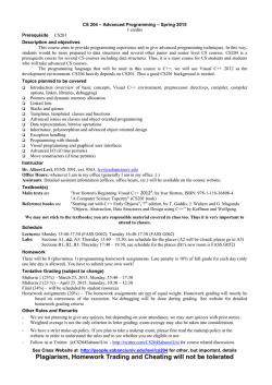
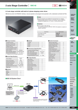
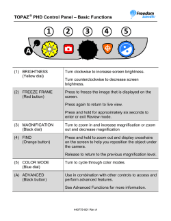
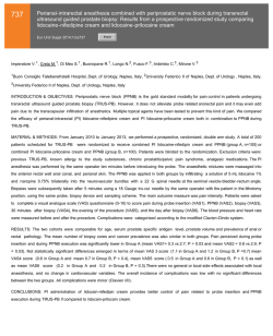
INSTRUCTION MANUAL GVIS 300 Video Inspection Scope GVIS 400 Video Inspection Scope GPAD 250 Portable Access Device Read and understand all of the instructions and safety information in this manual before operating or servicing this tool. Register this product at www.greenlee.com 52069973 REV 1 © 2014 Greenlee Textron Inc. 11/14 GVIS 300 • GVIS 400 • GPAD 250 Table of Contents Description Description............................................................................... 2 Safety....................................................................................... 2 Purpose of this Manual............................................................ 2 Important Safety Information................................................... 3 Contents................................................................................... 3 Operation.................................................................................. 4 GVIS 300 System and GVIS 400 High Definition Probe............................................ 4 GPAD 250 Portable Access Device...................................... 5 Typical Connection................................................................... 5 Specifications........................................................................... 6 Accessories.............................................................................. 6 Care and Maintenance............................................................. 7 Warranty................................................................................... 7 The GVIS 300 and GVIS 400 provide an easy-to-use video fiber connector inspection system. Their unique focus system eliminates the need for users to place their hands in the same position each time for effective focus control. To inspect the backplane connector, the user simply inserts the probe into the connector adapter. To focus, turn the entire probe 1/4 to 1/2 turn for complete focus range. No longer is it necessary for the user to keep one hand on a focus wheel. The GVIS 300 includes a bright 3.5 inch LCD with precision optics to provide a FOV (field of view) of 630 µm by 440 µm. Extended use lithium-ion batteries provide 8 to 10 hours of continuous use. When charging is necessary, the included “smart AC charger” charges the battery in 3 hours and allows the unit to continue to operate during the charging cycle. The GVIS 300 monitor is supplied in a padded nylon case. Both the probe and monitor are transported in a hard carry case that also includes the charger, extra adapter tips, and cleaning aids. GVIS Software Introduction.............................................................................. 9 System Requirements.............................................................. 9 Manual Installation of GVIS Software....................................... 9 Manual Installation of Software Drivers.................................. 10 Connecting Greenlee Devices to Your PC.............................. 10 GVIS Main Screen.................................................................. 11 GVIS Tablet Support........................................................... 11 Test Equipment....................................................................... 12 Starting GVIS.......................................................................... 12 GVIS Overview....................................................................... 13 Grading the Fiber End......................................................... 13 Tool Tips.............................................................................. 14 Main Tab............................................................................. 15 Reports Tab........................................................................ 20 Test Settings Tab................................................................ 21 Report Settings Tab............................................................ 23 Pass/Fail Settings Tab........................................................ 24 Help Tab.............................................................................. 24 Performing a Test................................................................... 25 Automatic Analysis............................................................. 25 Manual Grading.................................................................. 25 OPM Hold/Read................................................................. 28 OPM Save........................................................................... 28 Loss Measurement Prompt................................................ 28 Change Folder.................................................................... 29 Reporting............................................................................ 30 The GVIS 400 system consists of a GVIS 400-HDP high definition probe that has an FOV of 860 µm by 640 µm. The GVIS 400 probe can be plugged into the USB port of a personal computer for use with the GVIS software. The probe can also be plugged into the GPAD 250 portable access device. The GPAD 250 generates a wireless hotspot that can be used to interface to smart phones. The GVIS 300 and GVIS 400 are supplied with a universal 2.5 mm tip and a SC bulkhead adapter. Optional adapters for most commonly used connectors are available. Safety Safety is essential in the use and maintenance of Greenlee tools and equipment. This instruction manual and any markings on the tool provide information for avoiding hazards and unsafe practices related to the use of this tool. Observe all of the safety information provided. Purpose of this Manual This manual is intended to familiarize all personnel with the safe operation and maintenance procedures for the following Greenlee Communications tools: • GVIS 300 Video Inspection Scope • GVIS 400-HPD Video Inspection Scope • GPAD 250 Portable Access Device The free Greenlee Communications GVIS application can be downloaded at: Keep this manual available to all personnel. Replacement manuals are available upon request at no charge at www.greenlee.com. • greenlee.com • Google Play • Apple App Store Greenlee / A Textron Company 2 4455 Boeing Dr. • Rockford, IL 61109-2988 USA • 815-397-7070 GVIS 300 • GVIS 400 • GPAD 250 Contents Important Safety Information GVIS 300 • GVIS 300 monitor housed in a protective nylon padded pouch Read and understand all of the instructions and safety information in this manual before operating or servicing this tool. • GVIS 300 probe with 2.5 mm universal connector tip attached Failure to observe this warning could result in severe injury or death. • AC charger for GVIS monitor • 2.5 mm universal connector adapter tip • SC bulkhead adapter tip • Pen and square cleaning kit • USB cable Electric shock hazard: • Hard carry case Contact with live circuits could result in severe injury or death. • Instruction manual GVIS 400 • GVIS 400-HDP high definition probe (USB) • 2.5 mm universal connector adapter tip • Do not attempt to repair this tool. It contains no userserviceable parts. • SC bulkhead adapter tip • The GPAD 250 case houses a small fan that regulates the internal temperature of the device. Do not block the air vent while the GPAD 250 is powered on. • Hard carry case • Do not attempt to charge the GPAD 250 with any other charger than the only supplied. GPAD 250 Failure to observe these precautions may result in injury or property damage. • Instruction manual • Pen and square cleaning kit • Instruction manual • GPAD 250 portable access device Do not discard this product or throw away! For recycling information, go to www.greenlee.com. All specifications are nominal and may change as design improvements occur. Greenlee Textron Inc. shall not be liable for damages resulting from misapplication or misuse of its products. KEEP THIS MANUAL Greenlee / A Textron Company 3 4455 Boeing Dr. • Rockford, IL 61109-2988 USA • 815-397-7070 GVIS 300 • GVIS 400 • GPAD 250 Operation 4 GVIS 300 System and GVIS 400 High Definition Probe 1 2 5 6 7 3 8 9 10 11 GVIS 300 and GVIS 400-HDP Probes GVIS 300 Monitor GVIS 300 Probe and GVIS 400-HDP Probe GVIS 300 Monitor 1. Adapter Tip Ring – Adapter tips allow the GVIS 300 and GVIS 400 to access either the bulkhead panel connector or the actual connector end if access is available. The GVIS 300 and GVIS 400 are supplied with two adapters, the SC bulkhead adapter and a 2.5 mm universal adapter tip to allow inspection of any 2.5 mm ferrule connector (SC, ST, or FC). 4. Display Case – The display case includes the 3.5 inch LCD display, battery, and control features to display the required image. No user serviceable components are found inside. 5. Conn/Probe – This control button is for possible future functionality only. If the button is inadvertently pushed, push it again so that the display toggles back to the active probe display. To connect the appropriate adapter tip, place the tip on the end of the probe, being careful to screw the adapter to the adapter tip ring completely and finger tight only. Do not hold or turn the focus ring while attaching the adapter tip. For bulkhead adapters it is helpful to align the key of the adapter tip to the center position facing the user. 6. Probe Input – Insert the probe connector to the connector port located on the side of the GVIS 300 display case. Power to the probe is automatic and will remain powered while connected. To conserve battery use, remove the probe from the display case during periods of inactivity. 7. Brightness Control – Adjust brightness with the up/down arrow buttons. (The GVIS 300 has a default position of two positions below the brightest possible image.) This brightness control allows the user to discern defects with greater ease. 2. Focus Ring – Two focus methods are used to adjust the image while using the GVIS 300 and GVIS 400. The first technique is used when using any of the universal tips for direct connector inspection. To focus, insert the connector into the adapter tip and adjust the image by turning the focus ring with your thumb. 8. AC Charger input – If the GVIS 300 display does not illuminate the screen when powered on, then the battery must be charged. To charge the battery and simultaneously use the GVIS 300, insert the AC charger connector into the port on the lower left side of the display case. Total charge time is approximately 3 hours. A green LED on the charger indicates a fully charged battery. While charging, this LED remains red. To focus on the bulkhead connector surface, these probes use a unique focus system by using specially equipped adapter tips. These bulkhead tips include keyway devices to lock the GVIS probe into the bulkhead under inspection. To focus on the bulkhead, simply insert the bulkhead adapter tip into the bulkhead and rotate the probe slightly in either direction for full focus control. The probe may be held anywhere while rotating, allowing for much easier focus control. 9. Power On – This green LED indicates that power is available to the LCD and probe. During low battery conditions this LED remains in the off position. 3. Probe Body – The probe body houses the optical interface, camera system, and lighting system. The probe body contains no user-serviceable devices inside the housing. Refer to the maintenance section for proper care of the optical interface at the tip of the probe. 10. USB Port – Connect the accessory USB cable to the USB port on the GVIS 300 monitor and then to a USB port on a personal computer to view the image in the GVIS software. An image can then be viewed and saved within the GVIS application. 11. Power – Enable power to the GVIS 300 display by pressing the power control button. Pressing this button while the unit is on powers the unit OFF. Greenlee / A Textron Company 4 4455 Boeing Dr. • Rockford, IL 61109-2988 USA • 815-397-7070 GVIS 300 • GVIS 400 • GPAD 250 Operation GPAD 250 Portable Access Device 1 1. USB Port – Insert the USB probe connector into this port. 2 3 2. LED – Illuminates to indicate that the GPAD 250 is actively producing a Wi-Fi hotspot. 3. Power Switch – Used to turn the GPAD 250 on and off so that a Wi-Fi hotspot is activated. 4. Power Connection – To charge the battery, insert the AC charger into this connector. Total run time using the battery is approximately 4 hours. The battery can be recharged while the hotspot is active, but the re-charge will take longer. 4 5. Fan – Regulates the internal temperature of the GPAD 250. To prevent overheating, make sure that the fan output is not blocked. 5 Typical Connection Wi-Fi Greenlee / A Textron Company 5 4455 Boeing Dr. • Rockford, IL 61109-2988 USA • 815-397-7070 GVIS 300 • GVIS 400 • GPAD 250 Specifications Accessories GVIS 300 GVIS 300 and GVIS 400 Connector Adapters FOV (Field of View) 630 µm x 440 µm GAC 034B E2000 Adapter GVIS Resolution 3/4 micron GAC 040B SC Adapter GVIS Light Source Blue LED GAC 041B SC/APC Adapter GVIS Lighting Technique Coaxial GAC 042B FC Adapter GVIS Display Screen Size 3.5 inch diagonal GAC 043B FC/APC Adapter Battery Life 8–10 hours continuous GAC 044B LC Adapter GVIS Battery Charge Time 3 hours GAC 045B LC/APC Adapter Probe Dimensions 7" x 1" x 0.75" (180 mm x 25 mm x 19 mm) GAC 046B ST Adapter GVIS GAC 048B 1.25 mm Universal Adapter GVIS Monitor Dimensions 4.75" x 3.5" x 1.25" (120 mm x 89 mm x 32 mm) GAC 049B 2.5 mm Universal Adapter GVIS Weight (monitor, probe, and case) 1.2 lb (0.54 kg) GAC 047B MTP/APC Adapter Operating Temperature 32 °F to 122 °F (0 °C to 50 °C) GAC 050B MTP Straight Adapter Storage Temperature -40 °F to 158 °F (-40 °C to 70 °C) GAC 100B ODC Plug Tip GVIS GAC 101B ODC Socket Tip GVIS GAC 104B FC Adapter, 60-Degree Angled GVIS GAC 109B SC Adapter, 60-Degree Angled GVIS GAC 107B LC Adapter, 60-Degree Angle GVIS GVIS 400 Camera Megapixel, high definition, CMOS sensor FOV (Field of View) 860 µm x 640 µm Resolution <1 micron GVIS 300 Carry Case Lighting Technique Coaxial Focus System Proprietary external focus system Probe Output USB 2.0 GAC 103 Hard case for GVIS 300 monitor, GVIS 300/400 probe, GPAD 250, adapter tips, and charger PASS/FAIL Analysis User-selectable or IEC 61300-335 compliant software included 4923 Deluxe tool soft case for GVIS 300 monitor, GVIS 300/400 probe, GPAD 250, adapter tips, and charger Probe Dimensions 7" x 1" x 0.75" (180 mm x 25 mm x 19 mm) Weight (probe, case, and tips) 1.2 lb (0.54 kg) GPAD 250 Wi-Fi Connectivity 802.11 abgn Wi-Fi access point Battery 11.1 V lithium-ion Battery Life 4 hours Battery Charger AC wall pack 12.6 V lithium-ion Communication Distance 200' (60 m) (GPAD 250 to wireless device) Dimensions 4.5" L x 1.5" W x 2.75" H (114 mm x 38 mm x 70 mm) Weight 0.5 lb (0.25 kg) Greenlee / A Textron Company 6 4455 Boeing Dr. • Rockford, IL 61109-2988 USA • 815-397-7070 GVIS 300 • GVIS 400 • GPAD 250 Care and Maintenance GPAD 250 Battery Maintenance This precision optical device includes components that should be treated with care when handling. Although Greenlee Communications has designed this product with field ruggedness in mind, the user must take certain precautions when handling this device. Keep all protective dust caps in place when tool is not in use. The GPAD 250 includes a rechargeable lithium-ion battery capable of powering the unit for more than 4 hours of continuous use. The GPAD 250 includes a “smart charging adapter” that charges the GPAD 250 and shuts down the charging when complete. Approximately 3 hours is necessary for a full charge. Probe Optical Lens Care and Cleaning The optical lens assembly is located on the tip of the probe. To access the external surface of the lens assembly, remove the adapter tip. To remove the adapter, hold the adapter in one hand and gently rotate the adapter tip ring in a counterclockwise position with the other hand. Do not turn the focus ring to attempt to remove the adapter tips. Once the adapter tip is removed, the external lens assembly may be inspected and/ or cleaned. To clean this surface, gently wipe off debris with appropriate lens cleaning solutions. Warranty Greenlee Textron Inc. warrants this product against defective material and workmanship for a period of two years from date of shipment to the original customer. Display Maintenance The GVIS 300 display case comes housed in a padded protective nylon case. Although this case provides field abuse protection, the GVIS 300 display must be protected from direct impact. Should the display need surface cleaning, optical grade cleaning solutions and tissues may be used. GVIS 300 Battery Maintenance The GVIS 300 includes a rechargeable lithium-ion battery capable of powering the unit for more than 8 hours of continuous use. The GVIS 300 includes a “smart charging adapter” that charges the GVIS 300 and shuts down the charging when fully charged. Approximately 3 hours is necessary for a full charge. If the display does not power on when the power switch is pressed, insert the AC charger into the lower right side charge port. Power to the display will be restored once the charger is connected. Greenlee / A Textron Company 7 4455 Boeing Dr. • Rockford, IL 61109-2988 USA • 815-397-7070 GVIS 300 • GVIS 400 • GPAD 250 Greenlee / A Textron Company 8 4455 Boeing Dr. • Rockford, IL 61109-2988 USA • 815-397-7070 GVIS 300 • GVIS 400 • GPAD 250 Greenlee GVIS Software Instructions Introduction When connected to Greenlee’s GVIS 400-HDP or GVIS 300 field connector inspection system, the Greenlee GVIS software allows the user to inspect and save fiber connector end face images and pertinent data. GVIS also provides automated pass/fail analysis according to the IEC 61300-3-35 specification. System Requirements Operating System Compatibility • Windows Vista • Windows 7 • Windows 8 Software Requirements • Microsoft .NET Framework 4 or newer • Microsoft Visual C++ 2010 x86 Redistributable Windows Driver Requirements Imager Support • GVIS 400-HDP uses the UVC 1.1 driver included with Windows; no other driver installation is needed • GVIS 300 uses the Videology driver Serial Port Support If Greenlee’s GRP 460 power meter is to be used, download the FTDI serial port driver from http://www.ftdichip. com/Drivers/CDM/CDM20824_Setup.exe. Manual Installation of GVIS Software If you downloaded the software from Greenlee’s website, extract the files on your PC by running the installer. After the installer is finished, close it and then navigate to C:\Greenlee Software\GVIS and double click on setup.exe. Greenlee / A Textron Company 9 4455 Boeing Dr. • Rockford, IL 61109-2988 USA • 815-397-7070 GVIS 300 • GVIS 400 • GPAD 250 Manual Installation of Software Drivers Before connecting your Greenlee devices to your PC, load the required drivers by following the instructions below. Installation of FTDI Chip Driver for the Greenlee GRP 460 Download the FTDI Chip driver at http://www.ftdichip.com/Drivers/CDM/CDM20824_Setup.exe. Installation of UVC Driver for GVIS 400-HDP No driver installation is required for the GVIS 400-HDP; it is included with Windows Vista, Windows 7, and 8. Installation of Videology Driver for GVIS 300 Greenlee’s GVIS 300 requires a Videology Windows driver for proper operation. If the serial number on the GVIS 300 has a “C” appended to the end, navigate to the Videology/Windows 32-64-bit Cypress folder of the installation package and double click on SetupVid and follow the installation instructions. If there is no “C” after the serial number, then go to web page http://www.videologyinc.com/download.htm and download the SFT-04040 Windows driver and follow the installation instructions. Connecting Greenlee Devices to Your PC GVIS 400-HDP Connect the Greenlee GVIS 400-HDP cable to the PC’s USB port. Wait for Windows to load the UVC driver. You should see Windows report a message indicating the driver loaded successfully. GVIS 300 Connect the Greenlee GVIS 300 to a USB port on your PC using the supplied USB cable. Wait for Windows to load the driver you installed in the section above. You should see Windows report a message indicating the Videology Camera driver loaded successfully. GRP 460 Connect the Greenlee GRP 460 power meter to a USB port on your PC using the supplied USB cable. Wait for Windows to load the driver you installed in the section above. You should see Windows report two messages indicating the drivers loaded successfully. Greenlee / A Textron Company 10 4455 Boeing Dr. • Rockford, IL 61109-2988 USA • 815-397-7070 GVIS 300 • GVIS 400 • GPAD 250 GVIS Main Screen Figure 1. GVIS Main Screen – Landscape Mode GVIS Tablet Support GVIS is designed to be touch-friendly and supports screen rotation to make it more convenient when used with tablets. Figure 1 illustrates the main screen in the landscape mode; Figure 2 illustrates the main screen in the portrait mode. In this manual, all subsequent figures are illustrated in the landscape mode, but the operation of GVIS is the same in the portrait mode. Only the button sizes and locations are changed to accommodate the different orientation. Greenlee / A Textron Company 11 4455 Boeing Dr. • Rockford, IL 61109-2988 USA • 815-397-7070 GVIS 300 • GVIS 400 • GPAD 250 Figure 2. GVIS Main Screen – Portrait Mode Test Equipment A GVIS 400-HDP or GVIS 300 can be used for visual inspection with the Greenlee GVIS software. The GRP 460 power meter can be used to record power (dBm) or loss (dB) measurements. GVIS 400-HDP Visual Inspection Scope Plug the GVIS 400-HDP into a USB port of the PC. Power is supplied by the USB port. GVIS 300 Visual Inspection Scope Using the supplied USB cable, plug the GVIS 300 into a USB port on the PC. Apply power to the device. GRP 460 Optical Power Meter Using the supplied USB cable, plug the GRP 460 into a USB port of the PC. Apply power to the device. Starting GVIS Run Greenlee GVIS by double clicking on the GVIS icon on your desktop. Figures 3 and 4 illustrate the functions for each item on the main screen. Greenlee / A Textron Company 12 4455 Boeing Dr. • Rockford, IL 61109-2988 USA • 815-397-7070 GVIS 300 • GVIS 400 • GPAD 250 GVIS Overview Grading the Fiber End GVIS allows you to grade a fiber end face in two ways, automatic grading and technician (manual) grading. Automatic grading requires a Greenlee GVIS 400-HDP probe. To perform automatic grading, the technician connects the fiber to the GVIS 400-HDP, focuses the image, and presses the Analyze button. The Greenlee software performs and reports the analysis by comparing defects to the IEC 61300-3-35 2009 specification. See “Automatic Analysis” in the “Performing a Test” section for more information. A GVIS 400-HDP or GVIS 300 can be used for the manual graded method. For manual grading the technician connects the fiber to the probe, focuses the image, and grades the fiber end by visually inspecting the image. See “Manual Grading” in the “Performing a Test” section for more information. Figure 3. GVIS Functions – Automatic Grading Mode 1 – Tab selection 2 – PASS/FAIL indicator 3 – Live or Saved Image display window 4 – Status bar 5 – Optical power meter GRP 460 control and measurement 6 – Grading circles 7 – Automatic analysis button Greenlee / A Textron Company 13 4455 Boeing Dr. • Rockford, IL 61109-2988 USA • 815-397-7070 GVIS 300 • GVIS 400 • GPAD 250 Figure 4. GVIS Functions – Manual Grading Mode 1 – Tab selection 2 – PASS/FAIL indicator 3 – Live or Saved Image display window 4 – Status bar 5 – Optical power meter GRP 460 control and measurement 6 – Grading circles 7 – Pass/Fail buttons 8 – Hide/Show grading 9 – Sample obstruction overlay circles Tool Tips Hold the cursor over a button to display a tool tip describing its function. See Figure 5. Figure 5. Tool Tips Greenlee / A Textron Company 14 4455 Boeing Dr. • Rockford, IL 61109-2988 USA • 815-397-7070 GVIS 300 • GVIS 400 • GPAD 250 Main Tab The Main tab contains all of the functions to perform a test, but before starting a test, the technician should set up the appropriate settings by selecting the settings tabs. See the ”Settings Tabs” descriptions below. Analyze After the appropriate setup has been made under the settings tabs, the technician can perform an analysis of a fiber end face. The Analyze button is enabled when a fiber cable is plugged into the Greenlee 400-HDP and it’s focused. Capture Image When a live image is displayed in the image window, the Capture Image button is enabled on the Main tab. Click on Capture Image to open the Save File window. Here you can create a new folder to save the image or save it in an existing folder. When a fiber end image is saved, the information under the Report Settings tab (Customer Company Name, for example) is saved as well. Click on any of the saved images to load that image and the information about the image into GVIS. When a report is created, the customer information is reported with the image. Figure 6. Capture Image File Screen Live Image If a saved or analyzed image is displayed on the Main tab, click on the Live Image button to display the live stream from the GVIS 400-HDP or GVIS 300. Greenlee / A Textron Company 15 4455 Boeing Dr. • Rockford, IL 61109-2988 USA • 815-397-7070 GVIS 300 • GVIS 400 • GPAD 250 Enlarge Click the Enlarge button to display a larger version of the image displayed on the main screen, as shown in Figure 7. Click the Windows X button in the upper right corner or click the Exit button to close the Enlarge image window. Figure 7. Enlarged Image Window Greenlee / A Textron Company 16 4455 Boeing Dr. • Rockford, IL 61109-2988 USA • 815-397-7070 GVIS 300 • GVIS 400 • GPAD 250 Magnify and Center Click the Magnify and Center button to magnify the image displayed approximately 2.5 times and to center the fiber end face. See Figure 8. To return to the normal view, click the Full Field of View button. Figure 8. Magnify and Center Screen Voice On/Off Voice commands can be used in situations when both hands are busy. Voice commands can be turned on and off by clicking the Voice Commands button. When on, command feedback is given as illustrated in Figure 9. When green, the command was understood. When yellow, a command was understood but may have been misinterpreted. Red indicates the command was not understood. Below are a few voice commands that can be used rather than clicking on a button. Button Voice Command Capture Image “Capture Image” or “Cheese” Hold/Read* “Hold” or “Read” Save/Measure* “Save” or “Measure” Magnify & Center* “Center Image” or “Full View” Analyze “Analyze” Voice Commands On “Disable Voice” *For these commands you can use the same command to toggle between button states. For example, when you say “Center Image”, GVIS magnifies and centers the image. Rather than saying “Full View”, you can say “Center Image” again to return back to full view. Greenlee / A Textron Company 17 4455 Boeing Dr. • Rockford, IL 61109-2988 USA • 815-397-7070 GVIS 300 • GVIS 400 • GPAD 250 Figure 9. Voice Command Feedback Focus Bar The blue focus bar is located below the fiber end image on the Main tab. It is visible when a live image is displayed and the image is not totally blurred. It is an aid to help focus the image. When the focus ring on the Greenlee probe is rotated and the image becomes more focused, the red peak bar stays at the best focus achieved. Each time a new peak is reached, the image associated with the peak is saved in a temporary buffer. If the image becomes unfocused again after a peak is reached, the peak focused image is still saved. When the Analyze button is pressed, the best focused image is used – not the image displayed at the time the Analyze button was pressed. This helps to ensure the best focused image is used for the analysis. Greenlee / A Textron Company 18 4455 Boeing Dr. • Rockford, IL 61109-2988 USA • 815-397-7070 GVIS 300 • GVIS 400 • GPAD 250 Figure 10. Unfocused Fiber End Figure 11. Focused Fiber End Figure 12. A Focused Image Is Needed to Perform a Successful Automated Analysis Exit Click Exit to close GVIS. Greenlee / A Textron Company 19 4455 Boeing Dr. • Rockford, IL 61109-2988 USA • 815-397-7070 GVIS 300 • GVIS 400 • GPAD 250 Reports Tab The Reports tab contains the list of saved fiber end images. Using these images, there are two reports that can be created, GVIS and Site Loss. GVIS Report information includes fiber end face image(s) and power meter measurements for the selected test. See “GVIS Report” section. Site Loss Report creates an Excel report of all the images stored in the present selected folder. See “Site Loss Report” section. Figure 13. Reports Tab GVIS Report Button To create a GVIS report, select one or two fiber end images and click GVIS Report. Power Measurements: To include power measurements in a report, first select one or two images that you would like to associate with the power measurement. Then click the Save button on the Main tab when an appropriate loss measurement is displayed. Site Loss Report Button Creates an Excel report of all fiber end images in the selected folder. Clear Check Boxes Button Clears all check boxes. Change Folder Button Permits the technician to change or create a new folder. Ideally, a folder should be created for each test site; doing this allows site loss reports to be created easily. See “Site Loss Report” section. Greenlee / A Textron Company 20 4455 Boeing Dr. • Rockford, IL 61109-2988 USA • 815-397-7070 GVIS 300 • GVIS 400 • GPAD 250 Test Settings Tab Figure 14. GVIS Test Settings Tab Analysis Mode To change the mode of grading, click the Test Settings tab and choose Automatic or Manual in the Analysis Mode group. Automatic mode is not available if a GVIS 300 is selected for a video source. Fiber Type The two types of fiber the technician may choose are single-mode and multi-mode. So that the correct size critical zone is used during analysis, the technician must choose the correct fiber type. Single-mode diameter is 25 μm; multi-mode is 65 μm. Choosing a Video Source To select a video source, click on the drop-down box in the Video Source group. Greenlee probe names are Greenlee HDP Probe, USB 2.0 Camera, and Videology Camera. Greenlee / A Textron Company 21 4455 Boeing Dr. • Rockford, IL 61109-2988 USA • 815-397-7070 GVIS 300 • GVIS 400 • GPAD 250 Image Controls Image controls are only available when GVIS is in the manual analysis mode. You can adjust image brightness, contrast, sharpness, and gamma using these controls. Figure 15. Image Controls IEC Profile 61300-3-35 When performing a test using automatic analysis, you have to choose the IEC specification to compare defect sizes and locations. The specification is used to determine whether the end face passes or fails the test. The test choices are: • Single-mode UPC ≥ 45 dB • Multi-mode PC • Single-mode APC • Single-mode PC RL ≥ 26 dB Greenlee / A Textron Company 22 4455 Boeing Dr. • Rockford, IL 61109-2988 USA • 815-397-7070 GVIS 300 • GVIS 400 • GPAD 250 Report Settings Tab Figure 16. GVIS Report Settings Tab Test Information Information on the Report Settings tab contains information to help annotate a saved fiber end face image. Drop-down boxes contain information that is likely to be repeated. These lists can be added to by clicking the Add button next to the item. These are labeled Customer Company Name, Contact Name, Testing Company Name, Tester’s Name and Test Location. To delete an item from a list, select the item and press the Del button next to the item. Text boxes labeled Fibers From, Fibers To and Comment can be updated to reflect your test location. On the top header portion of the reports there is a space for a company name. The name that is entered into the Customer Company Name on the Report Settings tab is used to fill the header. Greenlee / A Textron Company 23 4455 Boeing Dr. • Rockford, IL 61109-2988 USA • 815-397-7070 GVIS 300 • GVIS 400 • GPAD 250 Pass/Fail Settings Tab Figure 17. Pass/Fail Settings Tab Loss measurement pass/fail limits can be set and enabled on this tab as shown in Figure 17. If enabled and the power meter measurement exceeds the set limit, the measurement is marked as Fail on the reports. Help Tab The Help tab contains the GVIS version number and software manual. It also contains user specific guides and end face zone details. Figure 18. Help Tab Greenlee / A Textron Company 24 4455 Boeing Dr. • Rockford, IL 61109-2988 USA • 815-397-7070 GVIS 300 • GVIS 400 • GPAD 250 Performing a Test Automatic Analysis To perform automatic grading, connect the fiber to the GVIS 400-HDP and focus the image. If the fiber needs cleaning, do so and reconnect the fiber to the GVIS 400-HDP, focus, and press the Analyze button. The GVIS software performs and reports the analysis by comparing defects to the IEC 61300-3-35 2009 specification and reports Pass or Fail with the number of defects that caused a failure in each zone. Defects that are colored in blue were found but are less than the specified size for the zone and are not considered a failure. Defects colored red are equal to or larger than the specified size and cause a failure. See IEC 61300-3-35 2009 specification for detailed information. To show detailed information about a defect, mouse-over the defect so that a pop-up window appears below the Pass/Fail box in the upper left hand corner. See Figure 19. To change the specification that is used to determine pass or fail, choose Test Settings tab and choose the desired specification before performing a test. Figure 19. Automatic Grading Screen Manual Grading Grading Obstruction Overlay The overlay is used to judge the size of any particles or scratches in the grading zones. The zones are based on the IEC 61300-3-35 specification. Click the Show Grading button to display grading circles as illustrated below. The overlay can be moved by clicking and dragging on the top bar of the overlay. To move the overlay to the home position, the lower righthand corner of the image, click the Home button. Greenlee / A Textron Company 25 4455 Boeing Dr. • Rockford, IL 61109-2988 USA • 815-397-7070 GVIS 300 • GVIS 400 • GPAD 250 Figure 20. Sample Obstruction Overlay Grading Circles To show or hide grading circles, click the Show/Hide Grading button. The grading circles (zones) are based on the IEC 61300-3-35 specification. Using the grading circles provided as a guide, the technician can judge and mark a fiber end face image Pass or Fail by clicking the appropriate button. If no grading is desired, press the None button. Figure 21. None/Pass/Fail and Show/Hide Buttons The grading circles can be centered on the fiber core by pointing the mouse at core center and right clicking or by clicking the Locate button. They also can be nudged left, right, up, or down by first clicking the fiber image then using the arrow keys on the keyboard. Press and hold the Shift key and press the arrow keys to move the grading circles by ten pixels. The grading circles can be resized by first clicking the fiber image and then using the mouse wheel or pressing and holding the Ctrl key and pressing the up or down arrows on the keyboard. Greenlee / A Textron Company 26 4455 Boeing Dr. • Rockford, IL 61109-2988 USA • 815-397-7070 GVIS 300 • GVIS 400 • GPAD 250 Figure 22. Grading Circles Displayed Figure 23. Grading Circles and Pass or Fail Displayed Greenlee / A Textron Company 27 4455 Boeing Dr. • Rockford, IL 61109-2988 USA • 815-397-7070 GVIS 300 • GVIS 400 • GPAD 250 OPM Hold/Read Clicking the OPM Read/Hold button freezes or resumes reading of the Greenlee GRP 460 power meter. OPM Save To save the power meter measurement, first select one or two fiber end images on the Reports tab and click OPM Save on the Main tab. You will be prompted by the screen in Figure 25. (Hint: Press and hold the Shift key and click the image if you want to select two images.) Figure 24. Two Fiber End Images Selected to Save Power Measurements to those Images Loss Measurement Prompt The Loss Measurement prompt assists in saving the power meter measurement for reports. When you choose No, in Figure 25, you are indicating the measurement is just for the trunk portion of the cable. If you choose Yes, you are indicating that the measurement includes the top sector jumper. Figure 25. Loss measurement Location Prompt – Always Just Trunk Disabled Greenlee / A Textron Company 28 4455 Boeing Dr. • Rockford, IL 61109-2988 USA • 815-397-7070 GVIS 300 • GVIS 400 • GPAD 250 Figure 26. Loss measurement Location Prompt – Always Just Trunk Enabled Location Number: Indicates the location you are making the measurement, for example location 1 of 12. It is important to enter the correct location number; otherwise, your reports will not be accurate. Increment Automatically: Check this if you want the location number to increment by one every time you make a measurement and save it to an image file. Reset: Resets the Location Number to 1. Always Just Trunk: Check this if your measurements are always trunk and do not include the top sector. If checked, you will not be prompted for top sector measurements as shown in Figure 26. Change Folder To change the folder where images are saved or create a new folder, click Change Folder. Figure 27. Change Folder Window Greenlee / A Textron Company 29 4455 Boeing Dr. • Rockford, IL 61109-2988 USA • 815-397-7070 GVIS 300 • GVIS 400 • GPAD 250 Reporting GVIS permits the user to create reports. Two types of reports are provided: GVIS Report and Site Loss Report. The GVIS Report information includes fiber end face image(s) and power meter measurements for the selected test. The Site Loss Report information includes all the tests for the folder selected and displayed at the bottom of the GVIS screen. Figures 28 and 29 illustrate these reports. GVIS Report Click on the GVIS Report button to display results similar to the figure below. To display the results, you must first select one or two images in the image list before clicking GVIS Report. (Hint: Hold Shift or Ctrl key while clicking for two images.) Figure 28. Loss Report Screen Greenlee / A Textron Company 30 4455 Boeing Dr. • Rockford, IL 61109-2988 USA • 815-397-7070 GVIS 300 • GVIS 400 • GPAD 250 Site Loss Report If you have Microsoft Excel installed on your computer, click on the Site Loss Report button to create a site loss report of all the optical power measurements made that are associated with the end face images presently displayed in the selected folder. Figure 29. Excel Site Loss Report Greenlee / A Textron Company 31 4455 Boeing Dr. • Rockford, IL 61109-2988 USA • 815-397-7070 4455 Boeing Drive • Rockford, IL 61109-2988 • USA • 815-397-7070 An ISO 9001 Company • Greenlee Textron Inc. is a subsidiary of Textron Inc. www.greenlee.com USA Tel: 800-435-0786 Fax: 800-451-2632 Canada Tel: 800-435-0786 Fax: 800-524-2853 International Tel: +1-815-397-7070 Fax: +1-815-397-9247


© Copyright 2026