
3-Channel Receiver Model 423-315LM OWNERS - LiftMaster
3-Channel Receiver
Model 423-315LM
OWNER'S MANUAL
The receiver can be used with a 3-Button control station to OPEN,
CLOSE or STOP a commercial door operator or gate operator. This
product is not for use with residential garage door operators.
NOTE: This product is only for use in the United States, Latin America
and Mexico.
INSTALLATION
The receiver and antenna use TV Type F coaxial connectors. The antenna
can be plugged directly onto the receiver or mounted to a bracket and
connected to the receiver with Model 86 Coaxial Cable Kit, depending on
your requirements.
Select a location for the receiver which allows access to the terminals and
space for the antenna (as far from metal structures as possible and
preferably with the antenna in an upright position). Fasten the receiver
securely with screws through the two holes provided in the cover flanges.
TO USE THE RECEIVER WITH A 3-BUTTON CONTROL
STATION AND A COMMERCIAL DOOR OPERATOR:
Consult your manufacturer’s control connection diagram for instructions
on connecting two or more 3-button control devices (Figure 1).
• Use a screwdriver to pry open the receiver cover.
NOTE: The slide switch is factory set to the N.C. position (otherwise the
operator will not operate). Verify this setting. Re-connect power to the
operator and the accessory transformer, if used.
• Select a remote control button to STOP the operator.
• Press and hold the selected remote control button.
• Then press and release the “learn” button labeled “A” on the receiver.
The adjacent indicator light will FLASH.
• Release the remote control button.
Repeat the procedure above with a second remote control button and
receiver “learn” button “B” to program the OPEN operation; and again
with the last remote control button and receiver “learn” button “C” to
program the CLOSE function of the operator.
Return the front cover to the receiver.
NOTE: If a remote control button is not pressed within 30 seconds, the
indicator light adjacent to the selected “learn” button will turn OFF.
In that case, repeat the programming.
To prevent possible SERIOUS INJURY or DEATH from electrocution:
• Be sure power is not connected BEFORE installing the receiver.
To prevent possible SERIOUS INJURY or DEATH from a moving gate
or garage door:
• ALWAYS keep remote controls out of reach of children. NEVER
permit children to operate, or play with remote control transmitters.
• Activate gate or door ONLY when it can be seen clearly, is properly
adjusted, and there are no obstructions to door travel.
• ALWAYS keep gate or garage door in sight until completely closed.
NEVER permit anyone to cross path of moving gate or door.
To prevent possible SERIOUS INJURY or DEATH, the use of
CONSTANT OPERATION on residential operators is PROHIBITED.
When a receiver is used to activate a commercial door operator, a
reversing edge MUST be installed on the bottom of the door. Failure
to install a reversing edge under these circumstances may result in
SERIOUS INJURY or DEATH to persons trapped beneath the door.
Figure 1
Example of Operator
Terminal Strip
RECEIVER
C(Blue)
24 Vac
1
CONTROL
STATION
2
B(Yellow)
A(Grey)
3
4
OPEN
STOP
Wire Nut
CLOSE
COMMON
STOP
CLOSE
OPEN
Wire Nut
Connect
Antenna
Figure 2
B
A
Stop
C
Close
Open
Remote control
buttons
Slide Switch – N.C. Position
TO USE THE RECEIVER TO OPERATE THREE COMMERCIAL
DOOR OPERATORS WITH A MULTI-FUNCTION REMOTE
CONTROL:
Receiver
(Bottom)
Operator
1 Common
1
2
3
2
Relay
3
24 v
4
Trans
Primary
Paired grey receiver wires
Figure 4
Transformer 95
Receiver
(Bottom)
Control
Station
1
Operator
1 Common
2
2
3
3
Trans
Primary
Relay
24 v
4
Paired grey receiver wires
Figure 5
Connect
Antenna
Operator no. 3
(Blue)
B
Operator no. 1
(Grey)
Slide Switch – N.O. Position
Output Rating.................................................. 5 Amps 28 Vac or DC Max.
Power................................................................... 18 - 30V ~, 30mA, 60Hz
18 - 30V
, 30mA
If the power is other than shown in specifications, accessory transformer
Model 95 is required. Model 86 Coaxial Cable Kit is also available.
RF Frequency ............................................................................... 315 MHz
Remote Controls — 361LM, 362LM, 81-315LM
For Open/Close/Stop functionality, use remote control models: 333LM or
363LM.
NOTICE: To comply with FCC and or Industry Canada (IC) rules, adjustment or modifications of this
receiver and/or transmitter are prohibited, except for changing the code setting or replacing the
battery. THERE ARE NO OTHER USER SERVICEABLE PARTS.
Tested to Comply with FCC Standards FOR HOME OR OFFICE USE. Operation is subject to the
following two conditions: (1) this device may not cause harmful interference, and (2) this device
must accept any interference received, including interference that may cause undesired operation.
© 2009, The Chamberlain Group, Inc.
All Rights Reserved
Operator no. 2
(Yellow)
A
Select a remote control
button to operate
each operator
SPECIFICATIONS
114A2591C
Control
Station
C
Commercial door operator no. 1 (without transformer)
Refer to Figure 3 for wiring connections:
Connect paired grey receiver wires to the operator terminal screws used
for the control station.
Also, connect bell wire to receiver terminal 1 and operator terminal screw
1; and receiver terminal 2 and operator terminal screw 3.
Commercial door operator no.1 (with transformer 95)
Refer to Figure 4 for wiring connections:
Connect bell wire to receiver terminal screws 1 and 2, and to transformer
terminals. Also, connect paired grey receiver wires to operator terminal
screws used for the control station.
Commercial door operator no. 2: Connect paired yellow wires from the
receiver to the operator terminal screws used for the control station.
Commercial door operator no. 3: Connect paired blue wires from the
receiver to the operator terminal screws used for the control station.
Use a screwdriver to pry open the receiver cover.
Set the slide switch to the N.O. position If this is not done, operator
no.1 may not operate properly.
Re-connect power to the operators(s) and to the transformer, if used.
• Select a remote control button to operate commercial door operator
no.1.
• Press and hold the selected remote control button. Then press and
release the “learn” button labeled “A” on the receiver. The adjacent
indicator light will FLASH.
• Release the remote control button. Operator no.1 will now operate when
the selected remote control button is pressed.
Repeat the procedure with the other two remote control buttons to
program the second operator (“learn” button “B”) and the third operator
(“learn” button “C”). Figure 5.
Return the cover to the receiver.
NOTE: If operator no.1 will not run, check to be sure the slide switch on
the receiver is set to the N.O. position.
NOTE: If a remote control button is not pressed within 30 seconds, the
indicator light adjacent to the selected “learn” button will turn OFF. In that
case, repeat the programming.
Figure 3
Receptor de 3 canales
Modelo 423-315LM
ADVERTENCIA
MANUAL DEL PROPIETARIO
ADVERTENCIA
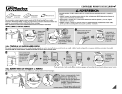
El receptor puede usarse con un control remoto de 3 botones para
ABRIR, CERRAR o PARAR un operador de garaje de puerta comercial o
operador de portón. No uso este producto con abre puertas
residenciales.
NOTA: Sólo uso este producto en los Estados Unidos, America Latino y
Mexico.
ADVERTENCIA
Para evitar una LESION GRAVE posible o la MUERTE por
electrocución:
• Asegúrese que la electricidad no está conectada ANTES de instalar el
receptor.
Para evitar una LESION GRAVE posible o la MUERTE de una
compuerta o puerta de garaje, móvil:
• SIEMPRE mantenga los controles remotos fuera del alcance de los
niños. NUNCA permita que los niños operen, o jueguen con los
transmisores de control remoto.
• Active la compuerta o puerta SÓLO cuando pueda verse claramente,
está bien ajustada y no hay obstrucciones al recorrido de la puerta.
• SIEMPRE mantenga la compuerta o puerta del garaje a la vista hasta
que esté completamente cerrada. NUNCA permita que nadie cruce la
trayectoria de una compuerta o puerta móvil.
PRECAUCIÓN
INSTALACIÓN
El receptor y la antena usan conectores coaxiales tipo F de TV. La
antena puede enchufarse directamente al receptor o montase en un
soporte y conectarse al receptor con un juego de cable coaxial Modelo
86, dependiendo de sus requerimientos.
Seleccione una ubicación para el receptor que permita acceso a los
terminales y espacio para la antena (tanto como sea posible para las
estructuras metálicas y preferiblemente con la antena en posición
vertical). Fije seguramente el receptor con tornillos a través de los dos
orificios provistos en las bridas de la cubierta.
ADVERTENCIA
USO DEL RECEPTOR CON UN ESTACIÓN DE CONTROL DE
3 BOTONES Y UN OPERADOR COMERCIAL:
Consulte su diagrama de conexión de control, del fabricante, para
instrucciones de conexión dos o más mecanismos de control de 3
botones (Figura 1).
• Use un destornillador para separar abierta la cubierta del receptor.
NOTA: El conmutador corredizo se gradúa de fábrica a la posición N.C.
(de otra manera el operador no funciona).Verifique esta graduación.
Reconecte la electricidad al operador y el transformador de accesorio, si
usado.
• Seleccione un botón de control remoto para PARAR (STOP) el
operador.
• Oprima y mantenga oprimido el botón de control remoto seleccionado.
• A continuación oprima y suelte el botón de "aprendizaje" rotulado "A"
en el receptor. La luz indicadora adyacente CENTELLEA.
• Suelte el botón de control remoto.
Repita el procedimiento de arriba con un segundo botón control remoto
y un botón "B" de "aprendizaje" del receptor para programar la operación
de ABRA (OPEN) y nuevamente con el último botón control remoto y el
botón "C" de aprendizaje del receptor para programar la función CIERRE
(CLOSE) del operador.
Retorne la cubierta delantera al receptor.
NOTA: Si no se oprime un botón de control remoto dentro de 30
segundos, la luz indicadora adyacente al botón de "aprendizaje" se apaga.
En ese caso repita la programación.
A
ADVERTENCIA
Para evitar una LESION GRAVE posible o la MUERTE, se prohibe la
OPERACION CONSTANTE de abre-puertas residenciales.
A
ADVERTENCIA
Cuando se usa un receptor para activar un operador comercial, DEBE
instalarse un borde revertido en la parte inferior de la puerta. El no
instalar un borde revertido bajo esas circunstancias puede resultar en
LESIONES GRAVES o la MUERTE a las personas atrapadas debajo de
la puerta.
PR
Ejemplo de operador
de banda termnal
Figura 1
RECEPTOR
C(Azul)
1
ADVERTENCIA
24Vca
ESTACIÓN DE
CONTROL
2
B(Amarillo)
3
A(Gris)
4
Tuerca
para cable
ABRA
PARAR
ADVERTENCIA
COMUN
CIERRE
PARAR
CIERRE
ABRA
Tuerca
para cable
Conecte
la antena
Figura 2
C
B
A
Botones del
control remoto
Conmutador corredizo – Posición N.C.
Cierre
Abra
Parar
PR
USO DEL RECEPTOR PARA OPERAR TRES OPERADORES
COMERCIAL CON UN CONTROL REMOTO
MULTIFUNCIONAL:
Receptor
(Parte inferior)
Botón
de pared
Operador
1
1
2
2
3
3
4
Relé
24V
Cables grises apareados del receptor
Figura 4
Transformador 95
Receptor
(Parte inferior)
Botón
de pared
1
1
2
2
3
3
4
Operador
Común
Transf.
primario
Relé
24V
Cables grises apareados del receptor
Figura 5
Conecte
la antena
Abre-puertas no. 3
(Azul)
B
Abre-puertas no. 1
(Gris)
Conmutador corredizo - Posición N.O.
Clasificación nominal de salida . . . . . . . . . . . . 5 Amps 28 Vca o CD, Máx.
Potencia . . . . . . . . . . . . . . . . . . . . . . . . . . . . . . .18V a 30V ~, 30mA, 60Hz
18V a 30V
, 30mA
Si la potencia es diferente a la indicada en las especificaciones, se
requiere el transformador Modelo 95. También está disponible el juegode
cable coaxial Modelo 86.
Frecuencia . . . . . . . . . . . . . . . . . . . . . . . . . . . . . . . . . . . . . . . . . . .315MHz
Controles remoto— 361LM, 362LM, 81-315LM
Para el característica ABRA (OPEN)/CIERRE (CLOSE)/PARAR (STOP), use
control remoto modelos: 333LM o 363LM.
AVISO: Para cumplir con las reglas de FCC o de Industria de Canadá (IC), se prohiben ajustes o
modificaciones de este receptor y/o transmisor, excepto por cambiar la graduación del código o reemplazo
de la pila. NO HAY OTRAS PIEZAS REPARABLES.
Probado para cumplir con los estándares de FCC PARA USO DEL HOGAR U OFICINA SOLAMENTE. La
operación está sujeta a las dos condiciones siguientes: (1) este mecanismo no puede causar interferencias
perjudiciales, y (2) este mecanismo debe aceptar cualquier interferencia recibida, incluyendo interferencia
que puede causar una operación indeseable.
© 2009, The Chamberlain Group, Inc.
Todos los derechos reservados
Abre-puertas no. 2
(Amarillo)
A
Seleccione un botón
de control remoto para
operar cada operador
ESPECIFICACIONES
114A2591C
Transf.
primario
Común
C
Operador de la puerta comercial no. 1 (sin transformador)
Refiérase a la Figura 3 para las conexiones de cableado:
Conecte los cables grises apareados del receptor apareados a los
tornillos terminales del operador usados para el estación de control.
También, conecte el cable del timbre al terminal 1 del receptor y al
tornillo terminal 1 del operador; y el terminal 2 del receptor y al tornillo
terminal 3 del operador.
Operador de la puerta comercial no. 1 (con transformador 95)
Refiérase a la Figura 4 para las conexiones de cableado:
Conecte el cable del timbre a los tornillos terminales 1 y 2 del receptor, y
a los terminales del transformador. También, conecte los cables grises
apareados del receptor a los tornillos terminales del receptor usados para
el estación de control.
Operador de la puerta comercial no. 2: Conecte los cables amarillos
apareados del receptor a los tornillos terminales del receptor usados para
el estación de control.
Operador de la puerta comercial no. 3: Conecte los cables azules
apareados del receptor a los tornillos terminales del receptor usados para
el estación de control.
Use un destornillador para separar abierta la cubierta del receptor.
Gradúe el conmutador corredizo a la posición N.O. Si esto no se hace,
el operador no. 1 no puede operar bien.
Reconecte la electricidad al (los) operadores y al transformador, si usado.
• Seleccione un botón remoto para operar el operador de la puerta
comercial no.1.
• Oprima y mantenga oprimido el botón de control remoto seleccionado.
A continuación oprima y suelte el botón de "aprendizaje" rotulado "A " en
el receptor. La luz adyacente indicadora CENTELLEA.
• Suelte el botón de control remoto. El operador no. 1 opera cuando se
oprime el botón de control remoto seleccionado.
Repita el procedimiento con los otros dos botones de control remotos
para programar el segundo operador ("botón de aprendizaje B") y el tercer
operador ("botón de aprendizaje C"). Figura 5.
Vuelva a colocar la cubierta en el receptor.
NOTA: Si el operador no. 1 no funciona, inspeccione para asegurarse que
el conmutador corredizo del receptor está graduado a la posición N.O.
NOTA: Si no se oprime el botón de control remoto dentro de 30
segundos, la luz indicadora adyacente al botón seleccionado de
"aprendizaje" se apaga. En ese caso, repita la programación.
Figura 3

© Copyright 2026