
Model 139.53783 Ten-Foot Rail Extension Kit - LiftMaster
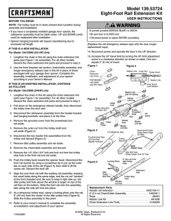
Ten-Foot Rail Extension Kit
Model 139.53729
BEFORE YOU BEGIN:
• The trolley must be in down (closed door) position during assembly and
installation. If you have a completely installed garage door opener, the rail/
opener assembly must be taken down. UP and DOWN Limits must be
readjusted after installation.
• Opener hanging brackets will require repositioning and the addition of an
extra bracket for stability due to increased rail length.
To prevent possible SERIOUS INJURY or DEATH:
• Disconnect ALL electric and battery power BEFORE performing ANY
service or maintenance.
IF THIS IS A NEW INSTALLATION:
The garage door MUST be in the fully closed position during
installation.
Use the front (header), belt assembly, and longer emergency release rope in
this kit in place of those packaged with your garage door opener. Add the
enclosed center rail as the second rail (remove one of the center rails
packaged with the garage door opener) section, creating a five piece rail
assembly. Complete the assembly, installation, and adjustment of your
opener according to your owner’s manual, with the exception of adding an
additional hanging bracket for stability.
Figure 1
Trolley
Connector
IF THIS IS AN EXISTING INSTALLATION, CONTINUE AS FOLLOWS:
1. Disconnect power to opener.
2. Pull down on the emergency release handle, then disconnect the trolley
from the door arm.
3. Disconnect the rail/opener assembly from the header bracket and
hanging brackets, and place it on the floor.
4. Remove the belt cap retainer from the opener sprocket and set aside.
5. Disconnect the master link from the trolley threaded shaft and belt;
discard (Figure 1).
6. Remove the spring/nut from the trolley and discard.
7. Remove idler pulley assembly and set aside.
8. Remove the belt assembly and discard.
9. Push the trolley back toward the opener. Disconnect the front rail and
second rail sections by using a screwdriver tip to pry up the outer tab on
each side of the rail (Figure 2), then slide it off the existing rail assembly.
Discard the front and second rails.
10. Align the new front and center rails with the existing rail assembly,
keeping the cut out “window” at the front (header) end. Be sure to keep
rails right side up: the idler pulley bolt hole above the window is larger
on top of the rail than on the bottom. Slide the new center rail onto the
assembly, then add the front rail. Tabs along the side will lock into place.
11. As a temporary stop, insert a screwdriver into the hole 10" (25 cm)
from the front end of the rail (Figure 1). Slide the trolley assembly to
this point.
12. Lay the new belt beside the rail. Grasp the end with the hooked trolley
connector and pass approximately 12" (30 cm) of belt through the
window. Keeping the ribbed side toward the rail, and allow it to hang
while you complete the next two steps.
13. Replace the idler pulley, lock washer and nut. Rotate it to be sure it
spins freely. Grease the center if necessary.
14. Locate the rail tab. Use a flathead screwdriver and lift the rail tab until
the tab is vertical (90°) (Figure 2).
15. Pull the belt around the idler pulley and hook the trolley connector into
the retaining slot on the trolley (Figure 1). The ribbed side must contact
the pulley.
16. With the trolley against the screwdriver, dispense the remainder of the
belt along the rail length toward the motor unit and around the sprocket
(Figure 1). The sprocket teeth must engage the belt.
Master
Link
Retaining
Slot
Master
Link
Threaded
Shaft
Front Rail
Section
Retaining
Slot
Trolley
Connector
Idler Pulley
Figure 2
To remove rail pry both
end tabs of front
rail slightly outward
CORRECT
Rail Tab
NEW
FRONT RAIL
INCORRECT
Rail Tab
Idler Bolt hole
(KEEP LARGER
ONE ON TOP)
17. Check to make sure the belt is not twisted, then connect it to the flat
end of the trolley threaded shaft with the master link (Figure 1):
• Push pins of master link bar through holes in end of belt and trolley
threaded shaft.
• Push master link cap over pins and past pin notches.
• Slide clip-on spring over cap and onto pin notches until both pins are
securely locked in place.
18. Insert the trolley threaded shaft through the hole in the trolley. Be sure
the belt is not twisted, and the ribbed side faces the rail.
19. Hold the belt at the trolley shaft as you thread the spring nut by hand
(Figure 3) onto the shaft until finger tight against the trolley. Do not use
any tools.
20. Remove the screwdriver.
21. Insert a flathead screwdriver tip into one of the nut ring slots and brace
it firmly against the trolley.
22. Tighten the spring trolley nut with an adjustable wrench or a 7/16" open
end wrench about a quarter turn until the spring releases and snaps the
nut ring against the trolley. This sets the spring to optimum belt tension
(Figure 3).
23. Replace the belt cap retainer and complete the re-installation and
adjustment of your opener according to your owner’s manual.
NOTE: Before hanging the opener, an additional hanging bracket is
necessary for stability.
24. Replace the old emergency release rope with the new, longer
replacement rope.
25. Reconnect power.
26. Make adjustments and test the safety reversal system according to the
owner's manual.
Figure 3
Nut Ring Slot
Spring Trolley Nut
Nut Ring
Nut Ring
BEFORE
AFTER
1" (2.5 cm)
1-1/4" (3.18 cm)
ADDING AN ADDITIONAL HANGING BRACKET:
Cut the enclosed hanging bracket (cross brace) to fit across the installed
hanging brackets. Fasten the cross brace to the top and bottom hole of
the hanging brackets (Figure 4) using 5/16" -18x7/8" hex bolts, 5/16 lock
washers and 5/16" -18 nuts.
Figure 4
To avoid possible SERIOUS INJURY from a falling garage door
opener, fasten it SECURELY to structural supports of the garage.
Concrete anchors MUST be used if installing any brackets into
masonry.
Hanging Bracket
(Cross Brace)
HARDWARE SHOWN ACTUAL SIZE
Bolt 5/16"-18x7/8"
Lock Washer 5/16"
Nut 5/16"-18
Hex Bolt
5/16"-18x7/8"
Lock Washer 5/16"
Nut 5/16"-18
Nut 5/16"-18
Lock Washer 5/16"
Hanging Bracket (Cross Brace) Not shown actual size
REPLACEMENT PARTS
Part No.
Description
183C158-14
183C157-10
41A5250-2
41A3021
4A1008
41B4103
Qty
Header Rail Extension
Center Rail Extension
10' Belt Assembly
Rope
Master Link Kit
Spring Nut Assembly
1
1
1
1
1
1
®Registered Trademark / ™ Trademark / SM Service Mark of Sears, Roebuck and Co.
®Marca Registrada / ™ Marca de Fábrica / SM Marca de Servicio de Sears, Roebuck and Co.
114A2753F
©2013 Sears, Roebuck and Co.
JUEGO DE EXTENSIÓN DE RIEL DE 10 PIES
Modelo 139.53729
ANTES DE COMENZAR:
• El carro portador debe estar en la posición hacia abajo (puerta cerrada) durante
el proceso de armar e instalar la extensión del riel. Si ya tiene un sistema de
apertura completamente instalado en la puerta del garaje, deberá desarmar el
conjunto de riel y abridor. Después de la instalación deberá volver a ajustar los
límites hacia ARRIBA y hacia ABAJO.
• Debido al incremento de la longitud del riel, será necesario reubicar las ménsulas
de soporte del abridor, y agregar un travesaño para conferirle mayor estabilidad.
SI ESTÁ REALIZANDO UNA INSTALACIÓN NUEVA:
Utilice la sección delantera (cabecera) del riel, la correa y la cuerda de liberación de
emergencia más larga que se proporcionan en este kit, en lugar de los que recibió
con el abridor de puerta de garaje. Instale el riel central suministrado, como segundo
riel (desinstale uno de los rieles centrales que recibió con el abridor de puerta de
garaje), creando un conjunto de cinco rieles. Lleve a cabo el armado, la instalación y
los ajustes de la unidad siguiendo las instrucciones del manual del abridor, a
excepción del travesaño adicional para conferirle mayor estabilidad.
Para evitar una LESIÓN GRAVE o INCLUSO LA MUERTE:
• Desconecte TODA alimentación eléctrica que llegue a la unidad (incluso
de una batería) ANTES de hacer CUALQUIER trabajo de reparación o
mantenimiento.
La puerta del garaje DEBE estar en la posición completamente cerrada
durante la instalación.
Figura 1
Conector
del trole
SI SE TRATA DE UNA INSTALACIÓN YA EXISTENTE, PROCEDA DE LA
SIGUIENTE MANERA:
1. Disconecte la energía eléctrica al abre-puertas del garaje.
2. Tire hacia abajo de la manija de liberación de emergencia y después desconecte
el carro portador del brazo de la puerta.
3. Desconecte el conjunto de riel y abridor del soporte delantero y los soportes de
suspensión, y coloque el conjunto en el suelo.
4. Quite el retén de capuchón de la correa, de la rueda dentada del abridor, y
guárdelo.
5. Desconecte el enlace maestro de la flecha roscada del carro y de la correa, y
deséchelo (Figura 1).
6. Quite el resorte y la tuerca del carro y deséchelos.
7. Quite el conjunto de polea-guía y guárdelo a un lado.
8. Quite la correa y deséchela.
9. Empuje el carro portador de modo que retroceda hacia el abridor. Desconecte los
sección del riel delantero y central, usando la punta de un destornillador para
separar la aleta externa de cada lado de los riel (Figura 2), a continuación deslice
hacia afuera el riel existente. Descarte el riel delantero y central.
10. Alinee la nueva sección delantera y el conjunto de riel existente, cuidando de que
el extremo con el orificio rectangular esté orientado hacia delante. Cerciórese de
orientar el lado correcto hacia arriba: el orificio para el perno de la polea-guía que
está arriba del orificio rectangular es más grande en la parte superior del riel que
en la parte inferior. Deslice la sección central del riel en el conjunto, a
continuación deslice la sección delantera. Las lengüetas laterales encajarán en su
sitio.
11. Ponga en el orificio un destornillador como tope temporal a 25 cm (10 pulg.) del
frente del riel (Figura 1). Deslice el trole hacia este punto.
12. Coloque la nueva correa al lado del riel. Tome el extremo que tiene el conectador
del carro en forma de gancho y pase por la ventana aproximadamente 30 cm (12
pulg.). Manteniendo el nervio de la correa hacia el riel, déjela suspendida hasta
que termine los dos siguientes pasos.
ADVERTENCIA
ADVERTENCIA
13. Vuelva a instalar la polea loca, la arandela y la tuerca. Gire la polea para
asegurarse de que rueda libremente. Engrase el centro si es necesario.
14. Ubica la pestaña del riel. Utilizar un destornillador de punta plana para levantar la
pestaña hasta que quede en posición vertical (a 90 grados) (Figura 2).
15. Instale la correa alrededor de la polea-guia y coloque el conector del carro en la
muesca de retención del carro (Figura 1). El lado con el nervio debe estar en
contacto con la polea.
16. Ponga el trole contra las pinzas y alimente el resto de la banda a todo lo largo del
riel hacia la unidad del motor y alrededor de la rueda dentada (Figura 1). Los
dientes de la rueda dentada deben retener la polea.
Enlace
Maestro
Orificio
con ranura
PRECAUCIÓN
PRECAUCIÓN
Enlace
Maestro
Eje roscado
Riel delantero
Orificio
con ranura
Conector
del trole
Polea de la cadena
Figura 2
Para extraer el riel separe
ambas aletas del
extremo del riel
delantero ligeramente
hacia arriba
Pestaña
del riel
EL NUEVO
RIEL DELANTERO
Pestaña
del riel
Mantenga
el orificio
(MÁS GRANDE
HACIA ARRIBA)
CORRECTO
INCORRECTO
17. Asegúrese de que la correa no esté torcida, y conéctela al extremo plano de la
flecha roscada del carro, mediante el enlace maestro (Figura 1):
• Coloque los pernos de la barra de enlace maestro en sus orificios, en el extremo
de la correa y de la flecha roscada del carro.
• Coloque la tapa del enlace maestro encima de los pernos, de forma que
sobrepase las indentaciones de los pernos.
• Coloque el resorte de clip encima de la tapa, sobre las indentaciones de los
pernos, hasta que ambos pernos estén firmes en posición.
18. Introduzca la flecha roscada a través del orificio en el carro. Asegúrese de que la
correa no esté torcida y que el nervio esté orientado hacia el riel.
19. Sujete la correa contra la flecha del carro mientras enrosca la tuerca de resorte
con la otra mano (Figura 3) en la flecha, y apriete la tuerca con los dedos; no
utilice ninguna herramienta.
20. Quite el destornillador.
21. Introduzca la punta de un destornillador plano en una de las ranuras del aro de la
tuerca yfijelo firmemente contra el carro.
22. Ajuste la tuerca del carro con resorte con una llave regulable o con una llave de
boca ancha de 7/16 de pulg, aproximadamente un cuarto de giro, hasta que se
suelte el resorte yelaro de la tuerca quede presionado contra el carro. En esta
posición, se obtiene la tensión óptima de la correa. Así optimizará la tensión de la
correa (Figura 3).
23. Vuelva a colocar el retén de capuchón de la correa y termine la reinstalación y el
ajuste del abridor según el manual del propietario. NOTA: Antes de montar el
abre-puertas es necesario instalar un travesaño adicional en la ménsula de
soporte para conferirle mayor estabilidad.
24. Cambie la cuerda de liberación de emergencia vieja por la nueva, que es más
larga.
25. Conectar la alimentación.
26. Hace ajustes y prueba el sistema de retroceso de reversa conforme a manual del
propietario.
Figura 3
Ranuras
del aro
Resorte/tuerca
del trole
Anillo de la tuerca
Anillo de la tuerca
ANTES
2.5 cm (1 pulg.)
DESPUES
3.18 cm (1-1/4 de pulg.)
INSTALACION DEL TRAVESAÑO ADICIONAL:
Corte la ménsula desoporte (travesaño) incluido con la unidad a la medida necesaria
para que quepa entre las dos ménsulas de soporte. Fije un extremo del travesaño al
agujero superior de una ménsula de soporte y el otro extremo al agujero inferior de la
otra ménsula de soporte (Figura 4) utilice tornillos de cabeza hexagonal de 5/16 pulg18x7/8 pulg., arandelas de presión de 5/16 pulg. y tuercas de 5/16 pulg.-18.
Para evitar la posibilidad de una LESIÓN GRAVE si se cae el abridor de la
puerta de cochera, sujételo FIRMEMENTE a los soportes estructurales de la
cochera. Se DEBEN usar sujetadores para concreto si alguna de las ménsulas
se va a instalar en mampostería.
Figura 4
Ménsula de soparte
(Travesaño adicional)
ESTAS PIEZAS SE MUESTRAN EN SU TAMAÑO REAL
Perno de
5/16-18x7/8 pulg.
Arandela de 5/16 pulg.
Tuerca de 5/16-18 pulg.
Perno hexagonal
de 5/16-18x7/8 pulg.
Tuerca de
5/16-18 pulg.
Arandela de 5/16 pulg.
Arandela de 5/16 pulg.
Tuerca de 5/16-18 pulg.
Ménsula de soporte (Travesaño adicional) No se muestra en tamaño real
PARTES DE REPUESTO
Nº de pieza
Descripción
Cant.
183C158-14
183C157-10
41A5250-2
41A3021
4A1008
41B4103
Extensión de riel delantero
Sección central del riel
Correa de 3 m (10 pies)
Cuerda
Kit de eslabón maestro
Tuerca de resorte
1
1
1
1
1
1
ADVERTENCIA
®Registered Trademark / ™ Trademark / SM Service Mark of Sears, Roebuck and Co.
®Marca Registrada / ™ Marca de Fábrica / SM Marca de Servicio de Sears, Roebuck and Co.
114A2753F
©2013 Sears, Roebuck and Co.
PR
© Copyright 2026