
Model 2100 GW Plural COMPONENT SPray GuN
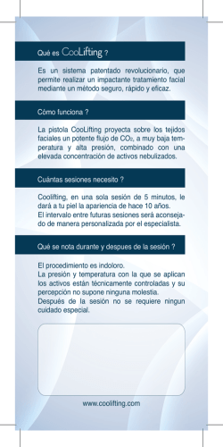
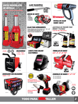
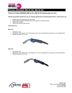
Model 2100 GW Plural Component Spray Gun 2101-XXXX-XGW General The 2100 GW gun is a lightweight, hand-held, plural component spray gun for spraying limited applications of two-component materials, such as gel-coats or polyesters. The spray gun is operated in the conventional manner. The trigger action starts, and stops, the spray of both materials simultaneously. The two materials exit separately as an atomized spray from their respective nozzles and impinge on each other approximately 6" in front of the gun (resin) nozzle. Here, the resulting turbulence insures intimate mixing. The “base” resin is “cured” by addition of a curative (catalyst) in a required ratio. In the 2100 GW gun, ratios of approximately 10:1 to perhaps 33:1 are possible by extending the curative with a compatible diluent. Preferably, the resin should be supplied from a pressure cup mounted either on the gun or located remotely from it. In some applications, a siphon cup may be acceptable. The curative is supplied from a siphon container assembly (57) mounted directly on the gun. Air, diverted from the gun handle, passes through the air adjusting valve (39) to the nozzle body (55) to provide the siphon action and to serve as atomizing air for the curative. The adjustable fluid control (44) meters the flow of curative. Since the curative container is a siphon device its vent hole must always be kept open. The vent hole is located in the cover at the rear (see illustration). Nozzle Characteristics and spray patterns The 2100 GW gun uses external atomizing nozzles* to produce finer atomization and better control of the spray pattern. The pattern can be changed from round to fan and to all intermediate shapes by adjusting the side port control (2) on the gun. The pattern also can be rotated to any position in 360º by loosening the retaining ring on the nozzle (12). Intimate intermixing and distribution of the curative within the primary material is maximum when the long dimension of the fan spray pattern is vertical (lined up with the gun handle). The resin delivery rate of external atomizing nozzles is in the low to medium range. See “Important Adjustment Note” page 2. Resin Volume Output Resin output is controlled by two variables: 1. Nozzle orifice size, air or resin. 2. Air and/or resin pressures. Precise resin pressures can best be controlled by a fluid regulator, tank, or pump pressure. Minute adjustments in flow can be made with the control screw (17) which restricts the travel of the resin needle (15). Curative Volume Output Output of the curative is controlled by four variables: 1. Curative nozzle orifice size. 2. Air adjustment control (39). 3. Adjustment of needle stem (44). 4. Extending (diluting) the curative. *Where atomization occurs entirely outside of the gun. NOTE The curative and resin mix with each other outside of the gun. Purging of the gun and nozzles is not necessary as catalyzed resin never enters the gun passages. Volume Rate of flow calculations Resin: With atomizing air off and with resin pressure on, dispense resin into a graduate or into a clean container (resin can be reused) for 15 seconds. Multiply this volume of resin by four to determine volume rate of flow per minute. Increase or decrease resin pressure as required to obtain desired volume rate of flow. Curative: Turn off resin supply to gun. Fill the container (45) with a measured amount of curative (a substitute fluid may be used such as a solvent or water.) Depress gun trigger and spray until fluid starts to “spit”. Check elapsed time and calculate volume rate of flow per minute. Repeat sampling, after resetting air adjusting valve (39) and/or needle stem (44) to obtain desired flow. Curative (residual less diluent) to resin volumetric ratio is specified by the chemical manufacturer. With polyesters, for example, the ratio usually is from 1/2 percent to a maximum of approximately four percent. These ratios are based on theoretical requirements, and laboratory samples of about one pint (500 cc) that cover minimum surface areas. However, spray applications cover maximum surface areas. For this reason, and because of loss of exothermic heat and, perhaps, some loss of curative in overspray, it is suggested that spray samples be made, and that optimum cure times be established by increase or decrease in the volume of curative. It should be noted that the air valve (9) is designed to open slightly before the resin valve (15). The air valve also allows the curative to flow before the resin does. For this reason, air Continued on page 6 Replaces Part Sheet 77-3047 Part Sheet 77-3047 In this part sheet, the words WARNING, CAUTION and NOTE are used to emphasize important safety information as follows: ! WARNING Hazards or unsafe practices which could result in severe personal injury, death or substantial property damage. ! Caution Hazards or unsafe practices which could result in minor personal injury, product or property damage. ! NOTE Important installation, operation or maintenance information. Warning Read the following warnings before using this equipment. Read the Manual Before operating finishing equipment, read and understand all safety, operation and maintenance information provided in the operation manual. Plural Component Materials Hazard Because of the vast number of chemicals that could be used and their varying chemical reactions, the buyer and user of this equipment must determine all facts relating to the materials used, including any of the potential hazards involved. Wear Safety Glasses Failure to wear safety glasses with side shields could result in serious eye injury or blindness. Noise Hazard You may be injured by loud noise. Hearing protection may be required when using this equipment. De-energize, DEPRESSURIZE, Disconnect and Lock Out All Power Sources During Maintenance Failure to De-energize, disconnect and lock out all power supplies before performing equipment maintenance could cause serious injury or death. Fire and Explosion Hazard Improper equipment grounding, poor ventilation, open flame or sparks can cause hazardous conditions and result in fire or explosion and serious injury. Operator Training All personnel must be trained before operating finishing equipment. Pinch Point Hazard Moving parts can crush and cut. Pinch points are basically any areas where there are moving parts. Equipment Misuse Hazard Equipment misuse can cause the equipment to rupture, malfunction, or start unexpectedly and result in serious injury. Know Where and How to Shut Off the Equipment in Case of an Emergency Keep Equipment Guards in Place Do not operate the equipment if the safety devices have been removed. Pressure Relief Procedure Always follow the pressure relief procedure in the equipment instruction manual. High Pressure Consideration High pressure can cause serious injury. Relieve all pressure before servicing. Spray from the spray gun, hose leaks, or ruptured components can inject fluid into your body and cause extremely serious injury. CA PROP 65 PROP 65 WARNING WARNING: This product contains chemicals known to the State of California to cause cancer and birth defects or other reproductive harm. IT IS THE RESPONSIBILITY OF THE EMPLOYER TO PROVIDE THIS INFORMATION TO THE OPERATOR OF THE EQUIPMENT. FOR FURTHER SAFETY INFORMATION REGARDING BINKS AND DEVILBISS EQUIPMENT, SEE THE GENERAL EQUIPMENT SAFETY BOOKLET (77-5300). 2 ! Warning when using Binks equipment with Methyl Ethyl Ketone Peroxide in Plasticizer OBSERVE the following precautions corrosive to the eyes – may cause blindness. may be fatal if swallowed. strong irritant. contamination or heat may lead to fire or explosive decomposition. combustible. Do not handle or use until safety precautions concerning Methyl Ethyl Ketone Peroxides in the Manufacturer’s literature have been read and understood. FIRST AID Contact with foreign materials, especially strong mineral acids, metals (including certain equipment and containers) or metal salts, or exposure to heat above 135° F (57° C) may lead to violent decomposition, releasing flammable vapors which may self-ignite. Do not get into eyes or on skin or clothing. Wear eye and skin protection when handling. Avoid breathing mist. Use with adequate ventilation. Store only it in the original closed container. Wash hands thoroughly after handling. Protect from direct sunlight, heat, sparks and other sources of ignition. Prevent contamination with foreign materials. Do not add to hot materials. EYES Wash immediately (seconds count) with water and continue washing for at least 15 minutes. Obtain medical attention. SKIN Wash with soap and water. Remove contaminated clothes and shoes and again wash thoroughly with soap and water. SWALLOWING Administer large quantities of milk or water. Obtain immediate medical attention for lavage. To maintain the chemical activity store below 100° F (38° C). In case of fire, use water spray, foam or dry chemical. In case of spill or leak, absorb or blend with inert, non-combustible material. Put in suitable container. Dispose of immediately in accordance with federal, state and local regulations. Do not reuse container as some of the original hazardous contents may still be present. Follow the above precautions in handling. READ & UNDERSTAND THE MATERIAL SAFETY DATA SHEET FROM MATERIAL SUPPLIER ! Warning Model 2100 GW Gun is constructed with components of aluminum alloy and SHOULD NOT be used with any Halogenated Hydrocarbon solvents. Halogenated hydrocarbon solvents can cause an explosion when in contact with aluminum components of a pressurized or closed fluid system (pumps, heaters, filters, etc.) The same possibility of an explosion is possible with the galvanized coatings in pressure tanks. The possibility of a non-flammable explosion increases greatly at high operating temperatures. The explosion could be of sufficient strength to cause bodily injury, death, and substantial property damage. Cleaning agents, coatings, or adhesives may contain halogenated hydrocarbon solvents. Check with your solvent and paint supplier. If you are now using a Halogenated Hydrocarbon Solvent in a pressurized fluid system with aluminum components or galvanized wetted parts, the following steps should be taken immediately: 1. Remove all pressure; drain and disconnect the entire system. 2. Inspect and replace all corroded parts. 3. Contact your solvent supplier for a non-halogenated solvent to flush and clean the system of all residues. Halogenated Solvents are defined as any hydrocarbon solvent containing any of the following elements: Chlorine “Chloro” (Cl) Bromine“Bromo” (Br) Fluorine“Fluoro” (F) Iodine“Iodo” (I) Of those listed, the Chlorinated Solvents will most likely be the type used as a cleaning agent or solvent in an adhesive or coating. The most common are: Methylene Chloride 1,1,1, Trichlorethane Perchlorethylene Although stabilizers have been added to some of the solvents to reduce their corrosive effect, we are aware of none that will prevent these solvents from reacting under all conditions with aluminum components or galvanized coatings. Previous use of the solvents under pressurized conditions, without incident, does not necessarily indicate that it can be considered safe. 3 Binks Model 2100 GW Spray Gun 26 2 20 ! CAUTION The fluid inlet is not meant to be removed or replaced. 12 21 1 15 13 14 17 16 18 3 28 7 29 22 19 24 4 8 5 11 25 35 9 39 23 10 53 54 27 55 59 Loosen Swivel Nut for Vertical Adjustment Horizontal Adjustment Vertical Axis Adjustment Axis Horizontal Adjustment Arc Vertical Adjustment Arc 4 44 56 30 6 43 42 41 40 Position vent at rear NOTE IMPORTANT ADJUSTMENT NOTE Do not apply force to valve (39) when adjusting catalyst bottle assembly (57). Do not force by hand. Doing so will break valve (39). Adjust vertical position only after loosening swivel nut (35) of valve (39). Adjust horizontal position only by holding body (55) and turning elbow (56) with wrench. This may require separating the valve and catalyst bottle assemblies from the gun at the swivel (35). 52 51 45 47 57 46 45 NOTE Use PTFE tape to ensure sealing and to prevent “galling” on all “wetted” catalyst threads. Binks Model 2100 GW Spray Gun Parts List When ordering, please specify Part No. ITEMPART ITEMPART NO.NO.DESCRIPTIONQTY. NO.NO.DESCRIPTIONQTY. 1 — 2100 gun body..............................1 2 54-3347side port control assembly.....1 3 54-1013material body..............................1 4 2-28-5 ❍n ★+ PTFE packing..................................1 5 56-164packing nut...................................1 6 54-5464 2100 trigger...................................1 7 20-5285-5 ❍n+o-ring viton..................................1 8 54-750-5 ❍n+spring..............................................1 9 54-1236air valve assembly......................1 10sgk-457air adjustment valve.................1 11 54-768air connection.............................1 12 see footnote 1air nozzle......................................1 13 54-918-5 ❍n+gasket.............................................1 14 see footnote 1fluid nozzle..................................1 15 see footnote 2fluid needle..................................1 16 54-1347-5 ❍n +spring..............................................1 17 54-1007control screw.............................1 18 54-304-5 ❍n+spring..............................................1 19 20-3757 n+o-ring..............................................1 20 54-738-5 ❍n+packing...........................................1 21 54-1014-5 ❍n +pin.....................................................1 22 54-1025 n+valve stem assembly..................1 23 82-126-5 ❍screw..............................................1 24 82-135-5 ❍nut...................................................1 25 82-158-5 ❍n+packing...........................................1 26 54-1780 •quick change sideport conTrol (optional) .................................1 27 jga-132 •plug ( optional)...........................1 28 82-469round brush.................................1 29omx-88flat brush........................................1 30 54-1020 STUD....................................................1 35 107-1672 SWIVEL ADAPTER............................... 1 39 107-1671 AIR ADJUSTING VALVE....................... 1 40 20-4997 nO-Ring (Silicone)................................1 41 20-3562 n 42 50-12 nWasher..............................................1 43 57-114 nSpring.................................................1 44 102-1818 Stem Assembly.................................1 45 102-2188 n Container & Cap Assembly...........1 46 102-2184 Tube....................................................1 47 20-6675JAMNUT..............................................1 51 102-2209 Cap Holder.......................................1 52 54-2788 Retainer Ring...................................1 53 46-1042 Air Nozzle (R6 Stainless Steel).........1 54 45-1023 Fluid Nozzle (J3 Stainless Steel).....1 55 102-1799 Nozzle Body.....................................1 56 20-3645 Street Elbow 1/8 NPT......................1 57 102-2210 Catalyst Bottle Assembly............1 59 102-2243 CATALYST ATOMIZING ASSY..............Ref. O-Ring (PTFE).....................................1 ❍ Available only as 5-Pack. n Also available in Spare Parts Kit 106-1154. See table below for kit content. Kit not furnished, please order separately. + Also available in Spare Parts Kit 6-229 (2100 Gun). See table below for kit content. Kit not furnished, please order separately. ★ Alternate needle packing (optional) 54-747-5. • Accessory item. I tem 40 (Silicone o-ring) furnished with gun is designed for MEKPO service. Item 41 (PTFE o-ring) alternate for item 40 when specified, is compatible with all solvents. However, it is not an elastomer and may present difficulty when attempting to achieve a comparable seal. 1 Be sure to specify number stamped on air nozzle and fluid nozzle, or see Nozzle Selection Chart. 2 Be sure to specify number stamped on needle valve stem and spray gun model when ordering. Spare Parts Kit 106-1154 complete Item Number 4 7 8 13 16 18 19 20 21 22 25 40 41 42 43 45 Quantity 1 1 1 2 1 1 1 2 1 1 1 1 1 1 1 1 Spare Parts Kit 6-229 2100 Gun only Item Number 4 7 8 13 16 18 19 20 21 22 25 Quantity 1 1 1 2 1 1 1 1 1 1 1 5 Binks Model 2100 GW Spray Gun Continued from page 1 should not be used to “blow-off” surfaces as this will also dispense curative. If the air is used to “blow-off” surfaces, the air adjusting valve assembly (39) serving the curative supply, must be closed. Since this procedure changes the setting of the air adjusting valve, it is suggested that the position of the air adjusting valve (39) be marked. This will permit returning quickly to the correct setting for flow of curative previously established. Varying the spray pattern The fan spray pattern can be changed quickly and easily by adjusting the side port control (2). Turning the knurled knob (2) clockwise until it is closed will give a round spray pattern; turning it counter-clockwise will change the pattern from round to elliptical, forming a fan-shaped spray. The width of the fan spray can be varied within the limits of the particular air nozzle being used. The long dimension (length) of the fan spray can be oriented either horizontally or vertically, or any other position in 360º, by turning the air nozzle (12) to the desired position and tightening the retainer ring. Varying the spray rate If a pressure cup is used, the amount of resin flow can be varied by regulating the air pressure on the cup. The amount of resin flow can also be varied by adjusting the control screw (17). Turning this screw clockwise reduces the flow, counter-clockwise increases it. Faulty Resin Spray Pattern A faulty spray is caused by an obstruction in the flow path, caused usually by dried material around the resin nozzle tip (14), or in the air nozzle (12), resulting from incomplete cleaning. To remove such obstructions, soak these parts in a solvent that will soften the dried material, then wipe them clean with a brush or cloth. Do not use metal instruments to clean the air nozzle or resin nozzle. These parts are precision machined and any damage to them will cause a faulty spray. If either the air or resin nozzle is damaged, the part must be replaced before a perfect spray can be obtained. Fluid Packing Replacement Remove resin control screw (17), spring (16) and needle (15). Remove resin packing nuts (5) and remove old packing (4) with a small stiff wire. Insert new packing (oiled lightly) and reassemble in reverse order. To “set” packing, insert needle (15), tighten packing nut (5) until needle movement is sluggish (held too tightly for the spring to move). Then loosen nut 1/2 to 3/6 turn. Correcting air leak through the gun Air leaking through the gun is caused by the valve stem assembly (22) not seating properly against the valve body. Remove valve body and valve stem assembly and clean thoroughly. Replace worn or damaged parts and reassemble in reverse order. Correcting air leak around air valve stem Air leaking around the air valve stem (22) may be caused by worn packing (25) or damaged air valve stem (22). Remove trigger (6), packing nut (24) and packing (25). Clean extended portion of air valve stem and inspect for damage. If stem is damaged, remove as described in previous paragraph. Replace stem, insert new packing, and reassemble in reverse order. 6 Cleaning the Gun—when used with “remote” pressure cup Shut off the air supply to the pressure cup and release the pressure in the cup. Leave the pressure release vent open. Hold a piece of cloth over the gun nozzle and depress the trigger. The air will back up through the resin nozzle and force the resin out of the hose and into the cup. Remove resin from cup. Clean out cup, close pressure release vent and pour in enough clean compatible solvent to clean out the hose and gun thoroughly. Spray this solvent through the fluid hose and gun until it comes through clean. Separate the gun from the resin hose. Hook up the resin hose to an air line and blow air through it until it is dry. Flushing with a siphon cup A compatible solvent may be siphoned through gun by inserting tube from siphon cup in an open container of solvent. Trigger gun intermittently to flush passageways and internal parts thoroughly. Preventative maintenAnce The 2100 GW gun requires only general preventative maintenance. This includes good housekeeping practices such as: 1. Periodic internal inspection and cleaning. 2.Lubrication of stud (trigger pivot) (30); exposed portion of needle (15); and needle valve spring (16). 3.Keep exterior of gun clean as possible. 4.Replace worn or broken parts. Replace seats that continue to leak after servicing. 5.Use wrenches on all hex nuts. Do not use pliers or vise grips. 6.Avoid “mixing” or interchanging nozzle and needle sets. Paired resin nozzles and needles develop distinctive wear patterns and should remain mated. 7.Avoid submerging entire gun in solvent as residue may clog internal air passages. 8.Avoid dropping gun. Cracked or broken parts could release resins or air under pressure. 9.Inspect seals when gun is disassembled for cleaning. Have a spare set available for replacement if required. 10.Use only a non-metal probe such as a nylon broom straw or round wooden toothpick to clear the orifice holes. General Gun Cleaning 1.Submerging the entire gun in solvent will not harm the metallic parts of the gun. However, the lubricant could be washed from the leather packings causing them to dry out and malfunction. In addition, residue from dirty solvent could clog internal air passages. Clean solvent MUST be used, IF IT IS NECESSARY to submerge the gun. 2.Remove the air nozzle when flushing solvent through the resin passages of the gun. 3.Air nozzles may be soaked in clean solvent for washing. The passageways in the external mix air nozzle are particularly critical. Always final rinse with a clean solvent to prevent residue from remaining behind in the minute holes. Do not clean the air nozzle with metal instruments. 4.Exterior surfaces of gun should be kept clean by wiping with a solvent-wet cloth. 5.Exercise care with the curative container and parts. Do not clean in the same solvent that was used in cleaning the gun as residual curative could cause gellation of resin fluid passages of the gun. Remove the curative assembly by separating at swivel nut (35). NOZZLE SELECTION CHART CFM @MAX. TYPE OF FLUID FLUIDAIRFLUID 30 50 70PATTERN TO BE SPRAYEDNOZZLESIZENOZZLENEEDLEPSIPSIPSI @ 8 IN. VERY THIN 14-16 SECONDS #2 ZAHN HEAVY OVER 28 SECONDS #2 ZAHN 66SS .070" 66SD 565 (45-6601) (1.8 mm) (46-6020) (47-56500) 7.9 12.1 10.5" 68SS .110" 68PB 568 (45-6801) (2.8 mm) (46-6032) (47-56800) 9.5 14.1 19.1 12.0" 2100GW ASSEMBLY ORDERING REFERENCE 2101-4307-9GW 66SS X 66SD 2101-5111-5GW 68SS X 68PB Model 105-1236 2100 GW REMOTE PRESSURE OUTFIT – 2 QUART 1 4 3 Parts List When ordering, please specify Part No. ITEMPARTPART NO.NO.DESCRIPTIONQTY.SHEET 1 2 3 4 2101-4307-9 80-295 71-1210 71-3380 2100 GW GUN (66SS X 66SD)........................................... 1 77-3047 2 QT. “STEADI-GRIP” PRESSURE CONTAINER.................. 1 77-2823 AIR HOSE ASSEMBLY......................................................... 1 FLUID HOSE ASSEMBLY..................................................... 1 2 7 WARRANTY This product is covered by Binks’ 1 Year Limited Warranty. Binks Sales and Service: www.binks.com U.S.A./Canada Customer Service 195 Internationale Blvd. Glendale Heights, IL 60139 630-237-5000 8 Toll Free Customer Service and Technical Support 800-992-4657 Toll Free Fax 888-246-5732 10/13 © 2013 Binks All rights reserved. Printed in U.S.A. PISTOLA PULVERIZADORA DE VARIOS COMPONENTES Modelo 2100 GW 2101-XXXX-XGW GENERAL La pistola 2100 GW es una pistola pulverizadora de mano liviana de varios componentes para atomizar aplicaciones limitadas de materiales de dos componentes, tales como recubrimientos con gel o poliésteres. La pistola pulverizadora se opera de manera convencional. La acción del disparador activa y detiene el atomizado de ambos materiales simultáneamente. Los dos materiales existen por separado como un rociado atomizado desde sus respectivas boquillas y entran en contacto a una distancia de 6" frente a la boquilla (resina) de la pistola. Aquí, la turbulencia que resulta asegura la mezcla íntima. La resina “base” se “cura” mediante la adición de un agente curativo (catalizador) en una relación requerida. En la pistola 2100 GW, relaciones de aproximadamente 10:1 a quizá 33:1 son posibles extendiendo el agente curativo con un diluyente compatible. Preferiblemente, la resina debe ser suministrada de una cubeta de presión instalada en la pistola o a distancia de la misma. En algunas aplicaciones, podría ser aceptable usar una cubeta de sifón. El agente curativo es suministrado desde un recipiente de sifón (57) instalado directamente en la pistola. El aire, desviado desde el mango de la pistola, pasa a través de la válvula de ajuste de aire (39) hasta el cuerpo de la boquilla (55) para permitir la acción de sifón y servir de aire atomizador para el agente curativo. El control de fluido ajustable (44) mide el flujo del agente curativo. DEBIDO A QUE EL RECIPIENTE DEL AGENTE CURATIVO EN UN DISPOSITIVO DE SIFÓN, SU ORIFICIO DE VENTILACIÓN SIEMPRE DEBE MANTENERSE ABIERTO. EL ORIFICIO DE VENTILACIÓN SE ENCUENTRA EN LA CUBIERTA, EN LA PARTE TRASERA (VER ILUSTRACIÓN). CARACTERÍSTICAS DE LA BOQUILLA Y PATRONES DE ATOMIZADO La pistola 2100 GW emplea boquillas de atomizado externas* para producir una atomización más fina y lograr un mejor control del patrón de atomizado. El patrón se puede cambiar de redondo a forma de abanico y a todas las formas intermedias ajustando el control del puerto lateral (2) en la pistola. El patrón se puede desplazar a cualquier posición dentro de un radio de 360° aflojando el anillo de retención en la boquilla (12). La mezcla íntima y la distribución del agente curativo dentro del material primario alcanzan su grado máximo cuando la dimensión larga del patrón de atomizado en forma de abanico es vertical (alineada con el mango de la pistola). El caudal de suministro de resina de las boquillas de atomizado externas es en el rango de bajo a mediano. Ver “Nota de ajuste importante” página 10. VOLUMEN DE SALIDA DE RESINA La salida de resina se controla por dos variables: 1. El tamaño del orificio de la boquilla, el aire o la resina. 2. Presiones del aire y/o la resina. Las presiones de resina precisas se pueden controlar mejor por un regulador de fluido, un tanque o la presión de la bomba. Los ajustes de los minutos en el flujo se pueden hacer con el tornillo de control (17) que restringe el desplazamiento de la aguja de la resina (15). VOLUMEN DE SALIDA DEL AGENTE CURATIVO La salida del agente curativo se controla por cuatro variables: 1. El tamaño del orificio de la boquilla del agente curativo. 2. Control de ajuste de aire (39). 3. Ajuste del vástago de la aguja (44). 4. Extendiendo (diluyendo) el agente curativo. *Donde la atomización ocurre totalmente fuera de la pistola. NOTA El agente curativo y la resina se mezclan entre sí fuera de la pistola. No es necesario purgar la pistola y las boquillas debido a que la resina catalizada nunca entra en los conductos de la pistola. CÁLCULOS DEL CAUDAL DE VOLUMEN DE FLUJO RESINA: Con el atomizador neumático desactivado y la presión de la resina activada, introduzca resina en un recipiente graduado o en uno limpio (la resina se puede reutilizar) durante 15 segundos. Multiplique este volumen de resina por cuatro para determinar el caudal de volumen de flujo por minuto. Aumente o disminuya la presión de la resina según sea necesario para obtener el caudal de volumen de flujo deseado. AGENTE CURATIVO: Interrumpa el suministro de resina a la pistola. Llene el recipiente (45) con una cantidad medida de agente curativo (se puede utilizar un fluido de reemplazo, como un disolvente o agua). Oprima el disparador de la pistola y atomice hasta que el fluido comience a “ser expulsado”. Verifique el tiempo transcurrido y calcule el caudal de volumen de flujo por minuto. Repita este procedimiento, después de reposicionar la válvula de ajuste de aire (39) y/o el vástago de la aguja (44) para obtener el flujo deseado. El fabricante de productos químicos especifica la relación volumétrica entre el agente curativo (residual menos diluyente) y la resina. Por ejemplo, con respecto a los poliésteres, la relación es usualmente de 1/2 por ciento a un máximo de aproximadamente cuatro por ciento. Estas relaciones se basan en requisitos teóricos y muestras de laboratorio de cerca de una pinta (500 cc) que cubren áreas de superficie mínimas. No obstante, las aplicaciones de atomización cubren áreas de superficie máximas. Por este motivo, y debido a la pérdida de calor exotérmico y, quizá, alguna pérdida de agente curativo por exceso de atomización, se sugiere hacer muestras de atomización y que se establezcan tiempos óptimos de curado aumentando o disminuyendo el volumen del agente curativo. Se debe tener en cuenta que la válvula de aire (9) está diseñada para abrirse ligeramente antes que la válvula de resina (15). La Continúa en la página 14 Hoja de piezas 77-3047 9 En esta hoja de piezas, las palabras ADVERTENCIA, PRECAUCIÓN y NOTA se emplean para enfatizar información de seguridad importante de la siguiente forma: ! ADVERTENCIA ! Prácticas peligrosas o inseguras que pueden ocasionar lesiones personales graves, la muerte o daño substancial a la propiedad. PRECAUCIÓN NOTA Prácticas peligrosas o inseguras que pueden ocasionar lesiones personales leves, daño al producto o a la propiedad. ! Información importante de instalación, operación o mantenimiento. ADVERTENCIA Lea las siguientes advertencias antes de utilizar el equipo. LEA EL MANUAL Antes de operar los equipos de acabado, lea y comprenda toda la información de seguridad, operación y mantenimiento incluida en el manual de operaciones. PELIGRO DE MATERIALES CON VARIOS COMPONENTES Debido al elevado número de sustancias químicas que se pueden utilizar y sus diferentes reacciones químicas, el comprador y el usuario de estos equipos deben determinar todos los factores relacionados con los materiales usados, incluyendo cualquiera de los peligros potenciales involucrados. PELIGRO DE RUIDO Usted puede resultar lesionado por el ruido muy fuerte. Podría necesitar protección de los oídos al usar este equipo. USE GAFAS PROTECTORAS No usar gafas protectoras con resguardos laterales puede ocasionar lesiones graves en los ojos o ceguera. Desactive, despresurice, desconecte y bloquee todas las fuentes de energía durante el mantenimiento. No desactivar, desconectar ni bloquear todas las fuentes de suministro de energía antes de realizar operaciones de mantenimiento en los equipos puede ocasionar lesiones graves o la muerte. PELIGRO DE INCENDIO Y EXPLOSIÓN La conexión a tierra indebida, la ventilación deficiente, llama abierta o las chispas pueden ocasionar condiciones de peligro y producir incendio o explosión y lesiones graves. CAPACITACIÓN DE LOS OPERADORES Todos los miembros del personal deben ser capacitados antes de operar los equipos de acabado. PELIGRO DE PUNTOS DE PRESIÓN Las partes móviles pueden aplastar y ocasionar cortaduras. Puntos de presión son básicamente todas las áreas donde haya partes móviles. PELIGRO DE USO INDEBIDO DEL EQUIPO El uso indebido del equipo puede ocasionar averías, mal funcionamiento o activación imprevista del equipo, lo que a su vez puede producir lesiones graves. SEPA DÓNDE Y CUANDO DESACTIVAR LOS EQUIPOS EN CASO DE EMERGENCIA MANTENGA LAS DEFENSAS DEL EQUIPO EN SU LUGAR No operar los equipos si los dispositivos de seguridad fueron retirados. PROCEDIMIENTO DE LIBERACIÓN DE PRESIÓN Siga siempre el procedimiento de liberación de presión que aparece en el manual de instrucciones del equipo. CONSIDERACIONES DE ALTA PRESIÓN La alta presión puede ocasionar lesiones graves. Antes de reparar o dar mantenimiento a los equipos, alivie toda la presión. El atomizado de la pistola pulverizadora, las filtraciones de la manguera o componentes averiados pueden inyectar fluido en su organismo y ocasionar lesiones sumamente graves. CA PROP 65 ADVERTENCIA DE PROP 65 ADVERTENCIA: Este producto contiene sustancias químicas que según información en poder del Estado de California produce cáncer, defectos de nacimiento y otros daños al sistema reproductor. ES RESPONSABILIDAD DEL EMPLEADOR SUMINISTRAR ESTA INFORMACIÓN AL OPERADOR DEL EQUIPO. PARA MÁS INFORMACIÓN DE SEGURIDAD ACERCA DE LOS EQUIPOS BINKS Y DEVILBISS, CONSULTE EL FOLLETO DE SEGURIDAD GENERAL DE LOS EQUIPOS (77-5300). 10 ! ADVERTENCIA Al utilizar equipos Binks con peróxido de metil etil cetona (MEKP) en plastificante OBSERVE las siguientes precauciones CORROSIVO PARA LOS OJOS – PUEDE OCASIONAR CEGUERA. PUEDE SER FATAL SI SE INGIERE. LA CONTAMINACIÓN IRRITANTE FUERTE O EL CALOR PUEDEN GENERAR UN INCENDIO O DESCOMPOSICIÓN EXPLOSIVA. COMBUSTIBLE. No manipule ni use el producto hasta haber leído y comprendido todas las precauciones de seguridad con respecto al peróxido de metil etil cetona contenidas en el material impreso del fabricante. PRIMEROS AUXILIOS OJOS Lávese inmediatamente (los segundos cuentas) con agua y continúe lavándose al menos 15 minutos. Obtenga atención médica. El contacto con materiales extraños, especialmente ácidos minerales fuertes, metales (incluyendo ciertos equipos y recipientes) o sales metálicas o exposición al calor sobre 135° F (57° C) puede resultar en una descomposición violenta, liberando vapores inflamables que pueden autoinflamarse. PIEL Lávese con jabón y agua. Quítese la ropa y los zapatos contaminados y vuelva a lavarse a fondo con jabón y agua. Evite el contacto con los ojos o la piel o prendas de vestir. Use gafas protectoras y protección para la piel al manipular el producto. Evite aspirar las sustancias vaporizadas. Úselo con ventilación adecuada. Guarde el producto únicamente en su recipiente original cerrado. Lávese las manos bien después manipular el producto. Protéjalo INGESTIÓN Administre grandes cantidades de leche o agua. Solicite atención médica inmediata de lavado gástrico. contra la luz directa del sol, el calor, las chispas y otras fuentes inflamables. Prevenga la contaminación con materiales extraños. No lo agregue a materiales calientes. Para mantener la actividad química almacene el producto por debajo de los 100° F (38° C). En caso de incendio, utilice agua en forma de aspersión, espuma o sustancia química seca. En caso de derrame o filtración, absorba o mezcle con material inerte y no combustible. Ponga el producto en un recipiente adecuado. Deséchelo de inmediato de acuerdo con los reglamentos federales, estatales y locales. No reutilice envases porque podrían tener algún contenido original peligroso. Siga las precauciones antedichas para manipular el producto. LEA Y ENTIENDA LA HOJA DE DATOS DE SEGURIDAD DE LOS MATERIALES DEL PROVEEDOR DEL MATERIAL ! ADVERTENCIA La pistola Modelo 2100 GW se fabrica con componentes de aleación de aluminio y NO SE DEBE utilizar con ningún solvente de hidrocarburo halogenado. LOS SOLVENTES DE HIDROCARBUROS HALOGENADOS PUEDEN CAUSAR UNA EXPLOSIÓN AL ENTRAR EN CONTACTO CON LOS COMPONENTES DE ALUMINIO DE UN SISTEMA DE FLUIDO PRESURIZADO O CERRADO (BOMBAS, CALEFACTORES, FILTROS, etc.) La misma posibilidad de una explosión es posible con los revestimientos galvanizados en los tanques a presión. La posibilidad de una explosión no inflamable aumenta considerablemente a altas temperaturas operativas. La explosión podría tener la suficiente fuerza para causar lesiones corporales, muerte y daño considerable a la propiedad. Los agentes de limpieza, revestimientos o adhesivos pueden contener SOLVENTES DE HIDROCARBUROS HALOGENADOS. CONSULTE CON SU PROVEEDOR DE SOLVENTES Y PINTURAS. Si está usando ahora un solvente de hidrocarburo halogenado en un sistema de fluido presurizado con componentes de aluminio o piezas galvanizadas humedecidas, debe seguir de inmediato los siguientes pasos: 1. Quite toda la presión; drene y desconecte todo el sistema. 2. Inspeccione y cambie todas las piezas corroídas. 3. Contacte a su proveedor de solvente por un SOLVENTE NO HALOGENADO para purgar y limpiar el sistema de todos los residuos. Los solventes HALOGENADOS se definen como cualquier solvente de hidrocarburo que contiene cualquiera de los siguientes elementos: CLORO BROMO FLúOR YODO “CLORO” (Cl) “BROMO” (Br) “FLÚOR” (F) “YODO” (I) De aquellos indicados, los solventes con cloro serán el tipo más probable de ser usado como agente de limpieza o solvente en un adhesivo o revestimiento. Los más comunes son: CLORURO DE METILENO 1,1,1, TRICLOROETANO PERCLOROETILENO Aunque se han agregado estabilizadores a algunos solventes para reducir su efecto corrosivo, no conocemos ninguno que prevenga que estos solventes reaccionen bajo todas las condiciones con componentes de aluminio o revestimientos galvanizados. El uso previo de solventes bajo condiciones presurizadas, sin incidentes, no indica necesariamente que esto puede considerarse seguro. 11 PISTOLA PULVERIZADORA Modelo 2100 GW de Binks 26 2 20 ! PRECAUCIÓN La entrada de fluido no se debe quitar ni reemplazar. 12 14 21 1 17 16 18 15 13 3 28 7 29 19 24 4 8 22 5 11 25 35 9 39 23 10 53 54 27 55 59 Afloje la tuerca giratoria para ajuste vertical Eje de ajuste horizontal Arco de ajuste horizontal Arco de ajuste vertical 12 Eje de ajuste vertical 44 56 30 6 43 NOTA NOTA DE AJUSTE IMPORTANTE No aplique fuerza a la válvula (39) al ajustar el conjunto del recipientecatalizador (57). No fuerce con la mano. Esto rompería la válvula (39). Ajuste la posición vertical únicamente después de aflojar la tuerca giratoria (35) de la válvula (39). Ajuste la posición horizontal únicamente sosteniendo el cuerpo (55) y haciendo girar la pieza acodada (56) con una llave inglesa. Para esto podría ser necesario separar la válvula y los conjuntos del recipiente-catalizador de la pistola en la tuerca giratoria (35). 42 41 40 Coloque el orificio de ventilación en la parte trasera 52 51 45 47 57 46 45 NOTA Use cinta PTFE para asegurar la obturación y prevenir la “excoriación” de todas las roscas del catalizador “humedecidas”. PISTOLA PULVERIZADORA Modelo 2100 GW de Binks LISTA DE PIEZAS Al hacer su pedido, sírvase especificar el número de la pieza ARTÍCULPIEZA ARTÍCULPIEZA NO.NO.DESCRIPCIÓN NO.NO.DESCRIPCIÓN CANT. 1 2 — CUERPO DE LA PISTOLA 2100.........1 54-3347CONJUNTO DEL CONTROL DEL PUERTO LATERAL.....................1 3 54-1013 CUERPO DEL MATERIAL...................1 4 2-28-5 ❍n★+ EMPAQUETAMIENTO PTFE..............1 5 56-164 TUERCA DE PRESIÓN........................1 6 54-5464 DISPARADOR 2100...........................1 7 20-5285-5 ❍n+EMPAQUETADURA DE VITÓN DE LA JUNTA TÓRICA......................1 8 54-750-5 ❍ n+RESORTE...........................................1 9 54-1236 CONJUNTO DE LA VÁLVULA DE AIRE.1 10sgk-457 VÁLVULA DE AJUSTE DE AIRE.........1 11 54-768 CONEXIÓN DE AIRE.........................1 12 see footnote 1 BOQUILLA DE AIRE..........................1 13 54-918-5 ❍n+EMPAQUE.........................................1 14 VER NOTA AL PIE 1 BOQUILLA DE FLUIDO.....................1 15 VER NOTA AL PIE 2 AGUJA DE FLUIDO...........................1 16 54-1347-5 ❍n +RESORTE...........................................1 17 54-1007 TORNILLO DE CONTROL..................1 18 54-304-5 ❍n+RESORTE...........................................1 19 20-3757 n+JUNTA TÓRICA.................................1 20 54-738-5 ❍n+EMPAQUETAMIENTO.......................1 21 54-1014-5 ❍n +CLAVIJA............................................1 22 54-1025 n+CONJUNTO DEL VÁSTAGO DE LA VÁLVULA...............................1 23 82-126-5 ❍TORNILLO.........................................1 24 82-135-5 ❍TUERCA.............................................1 25 82-158-5 ❍n+EMPAQUETAMIENTO.......................1 26 54-1780 •CONTROL DE PUERTO LATERAL DE CAMBIO RÁPIDO (OPCIONAL)...1 CANT. 27 jga-132 • 28 82-469 29omx-88 30 54-1020 TAPÓN (OPCIONAL)............................1 CEPILLO REDONDO.............................1 CEPILLO PLANO..................................1 PERNO.................................................1 35 107-1672 ADAPTADOR GIRATORIO................... 1 39 107-1671 VÁLVULA DE AJUSTE DE AIRE........... 1 40 20-4997 nJUNTA TÓRICA (silicona)....................1 41 20-3562 nJUNTA TÓRICA (PTFE).........................1 42 50-12 nARANDELA..........................................1 43 57-114 nRESORTE..............................................1 44 102-1818 CONJUNTO DEL VÁSTAGO.................1 45 102-2188 n CONJUNTO DEL RECIPIENTE Y LA TAPA...1 46 102-2184 TUBO...................................................1 47 20-6675 TUERCA FIADORA...............................1 51 102-2209 PORTA-TAPA.......................................1 52 54-2788 ANILLO DE RETENCIÓN......................1 53 46-1042BOQUILLA DE AIRE (acero inoxidable R6).........................1 54 45-1023BOQUILLA DE FLUIDO (acero inoxidable J3)..........................1 55 102-1799 CUERPO DE LA BOQUILLA.................1 56 20-3645 CODO MACHO Y HEMBRA 1/8 NPT...1 57 102-2210CONJUNTO DEL RECIPIENTE-CATALIZADOR.................1 59 102-2243CONJUNTO DE ATOMIZACIÓN DEL CATALIZADOR.............................Ref. ❍ Disponible únicamente como un paquete de 5. nTambién disponible en el kit de piezas de reemplazo 106-1154. Para el contenido del kit, consulte la Tabla abajo. No se provee el kit, sírvase hacer los pedidos por separado. +También disponible en el kit de piezas de reemplazo 6-229 (Pistola 2100). Para el contenido del kit, consulte la Tabla abajo. No se provee el kit, sírvase hacer los pedidos por separado. ★ Empaquetamiento de la aguja alternativo (opcional) 54-747-5. • Artículo accesorio. El artículo 40 (junta tórica de silicona) provisto con la pistola está diseñado para servicio MEKPO. El artículo 41 (junta tórica PTFE) alternativo para el artículo 40 cuando se especifica, es compatible con todos los solventes. No obstante, no es un elastómero y podría presentar dificultad cuando se intente lograr una obturación comparable. 1Asegúrese de especificar el número estampado en la boquilla de aire y en la boquilla de fluido o consulte la Tabla de selección de boquillas. 2Asegúrese de especificar el número estampado en el vástago de la aguja de la válvula y el modelo de la pistola pulverizadora al hacer su pedido. Kit de piezas de reemplazo 106-1154 completo Número de artículo 4 7 8 13 16 18 19 20 21 22 25 40 41 42 43 45 Cantidad 1 1 1 2 1 1 1 2 1 1 1 1 1 1 1 1 Kit de piezas de reemplazo 6-229 Pistola 2100 únicamente Número de artículo 4 7 8 13 16 18 19 20 21 22 25 Cantidad 1 1 1 2 1 1 1 1 1 1 1 13 PISTOLA PULVERIZADORA Modelo 2100 GW de Binks Viene de la página 9 válvula de aire permite también al agente curativo fluir antes que fluya la resina. Por este motivo, no se debe utilizar aire para “soplar” superficies debido a que esto también dispensaría agente curativo. Si se usa el aire para “soplar” superficies, se debe cerrar el conjunto de la válvula de ajuste de aire (39) que sirve al suministro de agente curativo. Debido a que este procedimiento cambia la posición de la válvula de ajuste de aire, se sugiere marcar la posición de la válvula de ajuste de aire (39). Esto permitirá volver rápidamente a la posición correcta para el flujo del agente curativo establecido anteriormente. CÓMO VARIAR EL PATRÓN DE ATOMIZADO El patrón de atomizado en forma de abanico se puede cambiar de forma rápida y fácil ajustando el control del puerto lateral (2). Hacer girar la tuerca moleteada (2) en sentido horario hasta que se cierre, producirá un patrón de atomizado redondo; hacerla girar en sentido antihorario cambiará el patrón de redondo a elíptico, formando un atomizado en forma de abanico. El ancho del atomizado en forma de abanico se puede variar dentro de los límites de la boquilla de aire específica que se esté utilizando. La dimensión larga (longitud) del atomizado en forma de abanico se puede orientar horizontal o verticalmente o a cualquier otra posición dentro de un radio de 360°, haciendo girar la boquilla de aire (12) hacia la posición deseada o apretando el anillo de retención. CÓMO VARIAR LA VELOCIDAD DE ATOMIZADO Si se utiliza una cubeta de presión, se puede variar la cantidad de flujo de resina regulando la presión del aire en la cubeta. La cantidad de flujo de resina también se puede variar ajustando el tornillo de control (17). Hacer girar este tornillo en sentido horario reduce el flujo, en sentido antihorario, lo aumenta. PATRÓN DE ATOMIZADO DE RESINA DEFECTUOSO El atomizado defectuoso se produce por una obstrucción en el conducto de flujo, ocasionada usualmente por material seco alrededor de la punta de la boquilla de resina (14) o en la boquilla de aire (12), debido a una limpieza incompleta. Para eliminar tal obstrucción, remoje estas piezas en un solvente que suavizará el material seco, luego límpielas con un cepillo o tela. No utilice instrumentos metálicos para limpiar la boquilla de aire o la boquilla de resina. Estas piezas son maquinadas a precisión y cualquier daño en ellas ocasionará un atomizado defectuoso. Si se daña la boquilla de aire o de resina, se debe reemplazar la pieza para obtener un atomizado perfecto. REEMPLAZO DEL EMPAQUETAMIENTO DEL FLUIDO Quite el tornillo de control de resina (17), el resorte (16) y la aguja (15). Quite las tuercas de presión de resina (5) y el empaquetamiento usado (4) con un alambre rígido pequeño. Inserte el nuevo empaquetamiento (aceitado ligeramente) y reensamble en orden inverso. Para “fijar” el empaquetamiento, inserte la aguja (15), apriete la tuerca de presión (5) hasta que el movimiento de la aguja sea lento (sostenida muy apretadamente para que se mueva el resorte). Luego afloje la tuerca de 1/2 a 3/6 de vuelta. CÓMO CORREGIR ESCAPES DE AIRE A TRAVÉS DE LA PISTOLA Los escapes de aire a través de la pistola se deben a que el conjunto del vástago de la válvula (22) no se aloja debidamente contra el cuerpo de la válvula. Quite el cuerpo de la válvula y el conjunto del vástago de la válvula y limpie bien. Reemplace las piezas dañadas o gastadas y reensamble en el orden inverso. CÓMO CORREGIR ESCAPES DE AIRE ALREDEDOR DEL VÁSTAGO DE LA VÁLVULA DE AIRE Los escapes de aire alrededor del vástago de la válvula de aire (22) pueden deberse a desgaste del empaquetamiento (25) o daño en el vástago de la válvula de aire (22). Quite el disparador (6), la tuerca de presión (24) y el empaquetamiento (25). Limpie la parte extendida del vástago de la válvula de aire e inspeccione para verificar si hay daño. Si el vástago está dañado, quítelo como se describe en el párrafo anterior. Reemplace el vástago, inserte el nuevo empaquetamiento, y reensamble en el orden inverso. 14 CÓMO LIMPIAR LA PISTOLA—CUANDO SE USA CON CUBETA A PRESIÓN “REMOTA” Interrumpa el suministro de aire a la cubeta de presión y reduzca la presión en la cubeta. Deje abierto el orificio de reducción de presión. Sostenga un trozo de tela con la mano sobre la boquilla de la pistola y oprima el disparador. El aire retrocederá a través de la boquilla de resina e impulsará la resina fuera de la manguera hacia la cubeta. Quite la resina de la cubeta. Limpie la cubeta, cierre el orificio de reducción de presión y vierta suficiente solvente compatible para limpiar completamente la manguera y la pistola. Atomice este solvente a través de la manguera de fluido y la pistola hasta que salga limpio. Separe la pistola de la manguera de resina. Enganche la manguera de resina en una línea de aire y sople aire a través de ella hasta que esté seca. CÓMO PURGAR CON UNA CUBETA DEL SIFÓN Se puede sifonear un solvente compatible a través de la pistola insertando un tubo de la cubeta del sifón en un recipiente de solvente abierto. Accione la pistola intermitentemente para purgar completamente los conductos y las piezas internas. MANTENIMIENTO PREVENTIVO La pistola 2100 GW requiere únicamente de mantenimiento preventivo general. Esto incluye buenas prácticas de limpieza y cuidado, tales como: 1. Inspección y limpieza interna periódica. 2.Lubricación del perno (giro del disparador) (30); la parte expuesta de la aguja (15); y la válvula resorte de la aguja (16). 3.Mantenga la parte exterior de la pistola limpia en la medida de lo posible. 4.Reemplace las piezas gastadas o rotas. Reemplace los alojamientos que continúen teniendo filtraciones después del mantenimiento o la reparación. 5.Utilice llaves inglesas en todas las tuercas hexagonales. No utilice pinzas ni tenazas de sujeción. 6.Evite “mezclar” o intercambiar juegos de boquillas y agujas. Las boquillas de resina y las agujas en pares desarrollan patrones de desgaste distintivos y deben permanecer emparejadas. 7.Evite sumergir la pistola completa en solvente debido a que los residuos pueden obstruir los conductos de aire internos. 8.Evite tirar la pistola. Las piezas rajadas o rotas pueden desprender resinas o aire bajo presión. 9.Inspeccione los obturadores cuando la pistola esté desarmado para limpieza. Tenga un juego de reemplazo disponible por si lo necesitara. 10.Utilice únicamente objetos no metálicos, como una paja de escoba de nylon o un mondadientes de madera redondeado, para limpiar los orificios. LIMPIEZA GENERAL DE LA PISTOLA 1.Sumergir la pistola completa en un solvente no dañará las piezas metálicas de la pistola. No obstante, el lubricante se puede eliminar de los empaquetamientos de cuero haciendo que se sequen y no funcionen bien. Además, los residuos de solventes sucios pueden obstruir los conductos de aire internos. Se DEBE utilizar solvente limpio, SI FUESE NECESARIO sumergir la pistola. 2.Quite la boquilla de aire al purgar solvente a través de los conductos de resina de la pistola. 3.Las boquillas de aire se pueden empapar en solvente limpio para su limpieza. Los conductos en la boquilla de aire externa son especialmente esenciales. Enjuague siempre con un solvente limpio para evitar que los residuos permanezcan en los orificios de minutos. No limpie la boquilla de aire con instrumentos metálicos. 4.Las superficies exteriores de la pistola deben limpiarse con regularidad con una tela humedecida con solvente. 5.Tenga cuidado con el recipiente del agente curativo y las piezas. No los limpie en el mismo solvente usado para limpiar la pistola, debido a que los residuos del agente curativo pueden ocasionar la gelación de los conductos de fluido de resina de la pistola. Quite el agente curativo separándolo en la tuerca giratoria (35). TABLA DE SELECCIÓN DE BOQUILLAS CFM @PATRÓN TIPO DE FLUIDO QUE BOQUILLA BOQUILLAAGUJA DE 30 50 70MÁX. SERÁ ATOMIZADODE FLUIDOTAMAÑODE AIREFLUIDOPSIPSIPSI @ 8 IN. MUY DILUIDO 14-16 SEGUNDOS #2 ZAHN 66SS .070" 66SD 565 (45-6601) (1.8 mm) (46-6020) (47-56500) 7.9 12.1 10.5" ESPESO MÁS DE 28 SEGUNDOS 68SS .110" 68PB 568 #2 ZAHN (45-6801) (2.8 mm) (46-6032) (47-56800) 9.5 14.1 19.1 12.0" REFERENCIA PARA PEDIR EL CONJUNTO DE 2100GW 2101-4307-9GW 66SS X 66SD 2101-5111-5GW 68SS X 68PB Modelo 105-1236 EQUIPO A PRESIÓN REMOTA 2100 GW - 2 CUARTOS 1 4 3 LISTA DE PIEZAS Al hacer su pedido, sírvase especificar el número de la pieza ARTÍCULPIEZAHOJA DE NO.NO.DESCRIPCIÓN CANT.PIEZAS 1 2 3 4 2101-4307-9 80-295 71-1210 71-3380 PISTOLA 2100 GW (66SS X 66SD)..................................... 1 77-3047 RECIPIENTE A PRESIÓN “STEADI-GRIP” DE 2 CUARTOS..... 1 77-2823 CONJUNTO DE LA MANGUERA DE AIRE......................... 1 CONJUNTO DE LA MANGUERA DE FLUIDO.................... 1 2 15 GARANTÍA Este producto está cubierto por la Garantía limitada de 1 año de Binks. Ventas y servicio Binks: www.binks.com Servicio al cliente en EEUU/Canadá 195 Internationale Blvd. Glendale Heights, IL 60139 630-237-5000 Teléfono gratuito a servicio al cliente y soporte técnico 800-992-4657 Fax gratuito 888-246-5732 10/13 © 2013 Binks Todos los derechos reservados. Impreso en EE.UU.
© Copyright 2026